EP1318343A2 - Steckverbindung - Google Patents
Steckverbindung Download PDFInfo
- Publication number
- EP1318343A2 EP1318343A2 EP02025215A EP02025215A EP1318343A2 EP 1318343 A2 EP1318343 A2 EP 1318343A2 EP 02025215 A EP02025215 A EP 02025215A EP 02025215 A EP02025215 A EP 02025215A EP 1318343 A2 EP1318343 A2 EP 1318343A2
- Authority
- EP
- European Patent Office
- Prior art keywords
- plug
- receptacle
- connection according
- connecting pin
- locking
- Prior art date
- Legal status (The legal status is an assumption and is not a legal conclusion. Google has not performed a legal analysis and makes no representation as to the accuracy of the status listed.)
- Granted
Links
Images



Classifications
-
- F—MECHANICAL ENGINEERING; LIGHTING; HEATING; WEAPONS; BLASTING
- F16—ENGINEERING ELEMENTS AND UNITS; GENERAL MEASURES FOR PRODUCING AND MAINTAINING EFFECTIVE FUNCTIONING OF MACHINES OR INSTALLATIONS; THERMAL INSULATION IN GENERAL
- F16L—PIPES; JOINTS OR FITTINGS FOR PIPES; SUPPORTS FOR PIPES, CABLES OR PROTECTIVE TUBING; MEANS FOR THERMAL INSULATION IN GENERAL
- F16L37/00—Couplings of the quick-acting type
- F16L37/08—Couplings of the quick-acting type in which the connection between abutting or axially overlapping ends is maintained by locking members
- F16L37/12—Couplings of the quick-acting type in which the connection between abutting or axially overlapping ends is maintained by locking members using hooks, pawls, or other movable or insertable locking members
- F16L37/138—Couplings of the quick-acting type in which the connection between abutting or axially overlapping ends is maintained by locking members using hooks, pawls, or other movable or insertable locking members using an axially movable sleeve
-
- F—MECHANICAL ENGINEERING; LIGHTING; HEATING; WEAPONS; BLASTING
- F16—ENGINEERING ELEMENTS AND UNITS; GENERAL MEASURES FOR PRODUCING AND MAINTAINING EFFECTIVE FUNCTIONING OF MACHINES OR INSTALLATIONS; THERMAL INSULATION IN GENERAL
- F16L—PIPES; JOINTS OR FITTINGS FOR PIPES; SUPPORTS FOR PIPES, CABLES OR PROTECTIVE TUBING; MEANS FOR THERMAL INSULATION IN GENERAL
- F16L33/00—Arrangements for connecting hoses to rigid members; Rigid hose-connectors, i.e. single members engaging both hoses
- F16L33/22—Arrangements for connecting hoses to rigid members; Rigid hose-connectors, i.e. single members engaging both hoses with means not mentioned in the preceding groups for gripping the hose between inner and outer parts
- F16L33/225—Arrangements for connecting hoses to rigid members; Rigid hose-connectors, i.e. single members engaging both hoses with means not mentioned in the preceding groups for gripping the hose between inner and outer parts a sleeve being movable axially
-
- F—MECHANICAL ENGINEERING; LIGHTING; HEATING; WEAPONS; BLASTING
- F16—ENGINEERING ELEMENTS AND UNITS; GENERAL MEASURES FOR PRODUCING AND MAINTAINING EFFECTIVE FUNCTIONING OF MACHINES OR INSTALLATIONS; THERMAL INSULATION IN GENERAL
- F16L—PIPES; JOINTS OR FITTINGS FOR PIPES; SUPPORTS FOR PIPES, CABLES OR PROTECTIVE TUBING; MEANS FOR THERMAL INSULATION IN GENERAL
- F16L37/00—Couplings of the quick-acting type
- F16L37/08—Couplings of the quick-acting type in which the connection between abutting or axially overlapping ends is maintained by locking members
- F16L37/12—Couplings of the quick-acting type in which the connection between abutting or axially overlapping ends is maintained by locking members using hooks, pawls, or other movable or insertable locking members
- F16L37/133—Couplings of the quick-acting type in which the connection between abutting or axially overlapping ends is maintained by locking members using hooks, pawls, or other movable or insertable locking members using flexible hooks
Definitions
- the invention relates to a connector for hose or Pipelines, especially for connecting and / or Connecting washing liquid lines of a motor vehicle, with a Plug-in receptacle for a connecting pin, the connecting pin in the socket against axially acting Forces can be locked securely.
- a disadvantage of known couplings is that the locking elements are difficult to handle. Often the washing liquid containers Pumps and similar components in motor vehicles are not freely accessible, so that the installation is limited by only available space is difficult. Connectors, which are designed to be pressure surge-tight, for example for high-pressure headlamp cleaning systems often particularly high assembly or locking forces. just as much Force is required to loosen the known plug connections required.
- Plug connections which originate from a first Coupling part and a second coupling part and another Locking element exist, the second coupling part usually against the locking element as a separate component an inner edge of the first, mostly pot-shaped Coupling part is biased. Snap tabs of the locking element penetrate the first coupling part in recesses and engage behind a shoulder of the second coupling part.
- the locking element is designed as a flat partial ring and for example made of spring steel.
- a disadvantage of this known coupling is that the locking element is difficult to grasp. Therefore, it is mostly on the outside of the locking element attached to a tab on the Tool can be applied. However, this tab leads often damage to abrasive lines and Cable. Furthermore, a for removing the locking element Tools required.
- Such a coupling has the disadvantage that initially when the coupling parts are inserted into each other in the direction of insertion there is no insertion resistance and none audible snapping or snapping of the connection takes place.
- another handle for fixing the Locking element required. Because of that extremely low Forces required to fit the coupling parts together are the control of the tight fit of the Coupling parts difficult into each other.
- the invention is therefore based on the object of a plug connection of the type mentioned in terms of handling to improve during assembly and disassembly.
- the Plug connection should continue to be designed so that this with the application of moderate joining or locking forces can be put together without a further operation for Securing the connection would be required.
- the plug-in spring-elastic or spring-loaded locking elements has that of one on the plug receptacle axially slidably arranged locking sleeve in a first Position of the same in a rest and recording position be held in which the connecting pin can be used and is lockable, and in a second position Resilience of the locking elements in a retracted open position allows.
- the connector according to the invention are preferably in one piece as locking elements spring tongues provided with the plug receptacle are provided, which each have outwardly protruding push tabs.
- the pressure lugs are in the first position of the locking sleeve under tension against the inner wall, so that the spring tongues in the flared position in the inner cross section protrude from the socket.
- the securing sleeve is preferably captive on the Plug receptacle arranged.
- the plug receptacle can, for example, have an end face have circumferential security collar, the with an inner circumferential shoulder of the locking sleeve as an axial Securing the same interacts.
- the plug receptacle is preferably on its outer circumference at least one locking projection provided with locking grooves the locking sleeve interacts, each of the functional positions the locking sleeve. This is ensures that the locking sleeve with respect to the Plug-in receptacle at least two defined functional positions can take.
- Both the plug receptacle and the are expedient Connection pin with axial holes for the passage of a Provide fluids.
- the plug receptacle preferably has an integrally molded one Connection spigot on that according to the Connection pin is formed.
- the plug connection provides that the axial bore of the plug receptacle with a diameter step into one preferably cylindrical receiving area opens.
- Sealing seat for the connecting pin may be provided in the area of the diameter of the plug-in receptacle.
- Sealing seat for the connecting pin may be provided.
- Sealing ring system there with an approximately mushroom-shaped head of the connecting pin interacts.
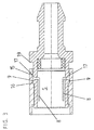
- the connector 1 shown in the figures includes a plug-in receptacle 2, a connecting pin that can be inserted into this 3a and one on the plug receptacle 2 axially displaceable arranged securing sleeve 4.
- the plug connection 1 is for connecting and / or connecting Washer fluid lines of a motor vehicle designed.
- the one from the Plug receptacle 2 enclosed connecting pin 3a assumes his remote from the receptacle 2, not shown End a choked washer fluid hose on.
- the plug receptacle 2 forms a hollow cylindrical receiving area 5 and is in the illustrated embodiment at its end remote from the receiving area 5 provided with an integrally molded connecting pin 3b.
- the connecting pin 3b is like the connecting pin 3a in cross section approximately mushroom-shaped and can also pick up the end of a hose line or in a correspondingly designed coupling counterpart or in an appropriately trained plug receptacle can be used.
- the parts described above are all injection molded parts made of thermoplastic material.
- the Wall 6 of the cylindrical or cup-shaped Receiving area 5 of the plug receptacle 2 as elastic locking elements two spring tongues 7 arranged opposite one another educated.
- the spring tongues 7 are integral with the wall 6 of the receptacle 2 is formed, namely by each approximately U-shaped recesses 8 in the wall 6.
- Die Spring tongues 7 are each with outwardly facing pressure lugs 9 provided with the inner contour as described below the locking sleeve 4 cooperate.
- the securing sleeve presses 4 which is placed on the socket 2 and surrounds them in the manner of a cuff, in a functional position the spring tongues 7 over the pressure lugs 9 in the inner cross section of the receiving area 5.
- the spring tongues 7 remain in the extended position Location.
- the plug-in receptacle 2 of the connection pin 3a in the receiving area 5 inserted, so the conical surface meets first 10 of the mushroom-shaped in cross section Connection pin 3a on the spring tongues 7.
- the receiving area 5 of the plug receptacle opens into the area a diameter step 12 in an axial bore 13 for passage of washing liquid.
- a sealing ring 14 made of soft elastic material is attached inserted into the receiving area 5 of the plug receptacle.
- the securing sleeve is 4 provided with circumferential locking grooves 15, 16, those with a complementary locking projection 17 cooperate on the outer surface of the plug receptacle 2 and in each case the functional positions of the securing sleeve 4 establish.
- a first locking groove 15 on the connection pin 3b facing Side of the locking sleeve 4 sets together with the Latching projection 17 the unlocked position of the securing sleeve 4 fixed, a second in the pull-out direction of the connecting pin 3a locking groove 16 arranged behind it folds together with the locking projection 17, the locking position of the Securing sleeve 4 firmly.
- the locking sleeve 4 By inserting a lever tool into the gap 18 the securing sleeve 4 from the plug-in receptacle 2 into the Fig. 3 shift position. In this position the locking sleeve 4 the spring tongues 7 jump into a cross section of the receiving area 5 releasing starting position back, the pressure lugs 9 in each case by the second locking groove 16 formed recess and the locking projection 17 in the depression formed by the first locking groove 15 lie. In this position the locking sleeve 4 is the connection pin 3a without any significant pull-out resistance Can be pulled out of the receiving area 5 of the plug-in receptacle 2.
- the plug-in receptacle 2 is delivered ready for installation in the state shown in Fig. 2, in which the spring tongues 7 of the securing sleeve 4 in a cross section of the receiving area 5 constricted position become.
- the connecting pin 3a can be inserted in this position and locked in the position shown in Fig. 1 become.
- the plug-in receptacle 2 has a front end outside circumferential securing collar 20 provided with a inner circumferential paragraph 21 of the securing sleeve as a protection against loss interacts.
Landscapes
- Engineering & Computer Science (AREA)
- General Engineering & Computer Science (AREA)
- Mechanical Engineering (AREA)
- Quick-Acting Or Multi-Walled Pipe Joints (AREA)
- Mechanical Coupling Of Light Guides (AREA)
- Surgical Instruments (AREA)
- Details Of Connecting Devices For Male And Female Coupling (AREA)
Abstract
Description
- Fig. 1
- Die Steckverbindung gemäß der Erfindung in zusam- mengesetzter und verrasteter Stellung im Schnitt,
- Fig. 2
- einen Schnitt durch die Steckaufnahme der Steck- verbindung in Aufnahmestellung,
- Fig. 3
- die in Fig. 2 dargestellte Steckverbindung im Schnitt, wobei sich der Sicherungshülse der Steck- verbindung in Offenstellung befindet und
- Fig. 4
- einen Schnitt durch die Sicherungshülse.
- 1
- Steckverbindung
- 2
- Steckaufnahme
- 3a, b
- Anschlusszapfen
- 4
- Sicherungshülse
- 5
- Aufnahmebereich
- 6
- Wandung
- 7
- Federzungen
- 8
- Aussparungen
- 9
- Drucknasen
- 10
- Mantelfläche
- 11
- Absatz
- 12
- Durchmesserstufe
- 13
- Axialbohrung
- 14
- Dichtring
- 15
- erste Rastnute
- 16
- zweite Rastnute
- 17
- Rastvorsprung
- 18
- Spalt
- 19
- Absatz
- 20
- Sicherungskragen
- 21
- Absatz
Claims (10)
- Steckverbindung für Schlauch- oder Rohrleitungen, insbesondere zum Anschließen und/oder Verbinden von Waschflüssigkeitsleitungen eines Kfz, mit einer Steckaufnahme für einen Anschlusszapfen, wobei der Anschlusszapfen in der Steckaufnahme gegen axial wirkende Kräfte gesichert verrastbar ist, dadurch gekennzeichnet, dass die Steckaufnahme (2) federelastische oder federbelastete Rastelemente aufweist, die von einer auf der Steckaufnahme (2) axial verschieblich angeordneten Sicherungshülse (4) in einer ersten Stellung derselben in einer Rast- und Aufnahmestellung gehalten werden, in welcher der Anschlusszapfen (3a) einsetzbar und verrastbar ist, und die in einer zweiten Stellung ein Einfedern der Rastelemente in eine zurückgezogene Öffnungsstellung ermöglicht.
- Steckverbindung nach Anspruch 1, dadurch ge- kennzeichnet, dass als Rastelemente vorzugsweise einstückig mit der Steckaufnahme (2) ausgebildete Federzungen (7) vorgesehen sind, die jeweils nach außen vorstehende Drucknasen (9) aufweisen.
- Steckverbindung nach einem der Ansprüche 1 oder 2, dadurch gekennzeichnet, dass die Drucknasen (9) in der ersten Stellung der Sicherungshülse (4) unter Vorspannung gegen die Innenwandung derselben anliegen.
- Steckverbindung nach einem der Ansprüche 1 bis 3, dadurch gekennzeichnet, dass die Sicherungshülse (4) unverlierbar auf der Steckaufnahme (2) angeordnet ist.
- Steckverbindung nach einem der Ansprüche 1 bis 4, dadurch gekennzeichnet, dass die Steckaufnahme (2) einen stirnseitig außen umlaufenden Sicherungskragen (20) aufweist, der mit einem innen umlaufenden Absatz (21) der Sicherungshülse (4) als axiale Sicherung derselben zusammenwirkt.
- Steckverbindung nach einem der Ansprüche 1 bis 5, dadurch gekennzeichnet, dass die Steckaufnahme (2) an ihrem Außenumfang mit wenigstens einem Rastvorsprung (17) versehen ist, der mit Rastnuten (15, 16) der Sicherungshülse (4) zusammenwirkt, die jeweils die Funktionsstellungen der Sicherungshülse (4) festlegen.
- Steckverbindung nach einem der Ansprüche 1 bis 6, dadurch gekennzeichnet, dass die Steckaufnahme (2) als auch der Anschlusszapfen (3a) mit einer Axialbohrung (13) zur Durchleitung eines Fluids versehen sind.
- Steckverbindung nach einem der Ansprüche 1 bis 7, dadurch gekennzeichnet, dass die Steckaufnahme (2) einen einstückig angeformten Anschlusszapfen (3b) aufweist, der entsprechend dem aufzunehmenden Anschlusszapfen (3a) ausgebildet ist.
- Steckverbindung nach einem der Ansprüche 1 bis 8, dadurch gekennzeichnet, dass die Axialbohrung (13) der Steckaufnahme (2) mit einer Durchmesserstufe (12) in einen Aufnahmebereich (5) mündet.
- Steckverbindung nach einem der Ansprüche 1 bis 9, dadurch gekennzeichnet, dass im Bereich der Durchmesserstufe (12) der Steckaufnahme (2) ein Dichtsitz für den Anschlusszapfen (3a) vorgesehen ist.
Applications Claiming Priority (2)
| Application Number | Priority Date | Filing Date | Title |
|---|---|---|---|
| DE10159280A DE10159280B4 (de) | 2001-12-04 | 2001-12-04 | Steckverbindung |
| DE10159280 | 2001-12-04 |
Publications (3)
| Publication Number | Publication Date |
|---|---|
| EP1318343A2 true EP1318343A2 (de) | 2003-06-11 |
| EP1318343A3 EP1318343A3 (de) | 2003-12-17 |
| EP1318343B1 EP1318343B1 (de) | 2006-01-18 |
Family
ID=7707847
Family Applications (1)
| Application Number | Title | Priority Date | Filing Date |
|---|---|---|---|
| EP02025215A Expired - Lifetime EP1318343B1 (de) | 2001-12-04 | 2002-11-12 | Steckverbindung |
Country Status (4)
| Country | Link |
|---|---|
| US (1) | US6854772B2 (de) |
| EP (1) | EP1318343B1 (de) |
| AT (1) | ATE316222T1 (de) |
| DE (2) | DE10159280B4 (de) |
Families Citing this family (29)
| Publication number | Priority date | Publication date | Assignee | Title |
|---|---|---|---|---|
| FR2855588B1 (fr) * | 2003-05-28 | 2006-05-05 | Legris Sa | Dispositif de raccordement instantane |
| DE10355535B4 (de) * | 2003-11-27 | 2009-08-27 | A. Raymond Et Cie | Vorrichtung zum abgedichteten Verbinden von zwei Endstücken |
| DE20319558U1 (de) * | 2003-12-17 | 2005-04-28 | Voss Automotive Gmbh | Steckbarer und verrastbarer Leitungsverbinder |
| DE102004040033A1 (de) * | 2004-08-18 | 2006-02-23 | Siemens Ag | Leitungskupplung |
| US20060087118A1 (en) * | 2004-10-26 | 2006-04-27 | Itt Manufacturing Enterprises, Inc. | Fluid quick connector with adapter |
| US7575024B2 (en) * | 2005-11-05 | 2009-08-18 | Snap-Tite Technologies, Inc. | Threaded coupling with flow shutoff |
| US7762279B2 (en) | 2005-11-05 | 2010-07-27 | Snap-Tite Technologies, Inc. | Threaded coupling with flow shutoff |
| US20100032943A1 (en) * | 2008-08-08 | 2010-02-11 | Globe Union Industrial Corp | Quick installed joint assembly |
| JP4692663B2 (ja) * | 2009-03-31 | 2011-06-01 | 株式会社デンソー | コネクタ |
| EP2563715A2 (de) * | 2010-04-19 | 2013-03-06 | Atmi Bvba. | Abflusskonnektor zur fluidverarbeitung und lagerungsbehälter dafür |
| US11628267B2 (en) | 2010-08-04 | 2023-04-18 | Medline Industries, Lp | Universal medical gas delivery system |
| DE102011115400A1 (de) | 2011-10-06 | 2013-04-11 | Daimler Ag | Steckverbindung eines Kraftfahrzeugs |
| DE102011120637A1 (de) * | 2011-12-09 | 2013-06-13 | Schott Schweiz Ag | Verschluss, insdesondere Spritzenverschluss zum abdichtenden Verschließen einer distalen Öffnung eines Spritzenkörpers |
| US8657343B2 (en) | 2012-02-06 | 2014-02-25 | Watts Water Technologies, Inc. | Quick connector assembly |
| US9022432B2 (en) * | 2012-07-09 | 2015-05-05 | Zachariah John Firestine | Apparatus and method of coupling electrical conduit |
| DE102012213089A1 (de) * | 2012-07-25 | 2014-01-30 | Hamilton Bonaduz Ag | Kopplungsausbildung eines Pipettierkanals einer Pipettiervorrichtung zur Ankopplung einer Pipettierspitze daran |
| US9671052B2 (en) | 2015-10-27 | 2017-06-06 | Whirlpool Corporation | Collet securing device for joining two fluid lines and providing lateral support at the connection of the two fluid lines |
| US10557469B2 (en) | 2016-03-22 | 2020-02-11 | Whirlpool Corporation | Multi-outlet fluid flow system for an appliance incorporating a bi-directional motor |
| US10655266B2 (en) | 2016-11-30 | 2020-05-19 | Whirlpool Corporation | Lint processing fluid pump for a laundry appliance |
| US10662574B2 (en) | 2017-02-27 | 2020-05-26 | Whirlpool Corporation | Self cleaning heater exchanger plate |
| US10480117B2 (en) | 2017-02-27 | 2019-11-19 | Whirlpool Corporation | Self cleaning sump cover |
| US10619289B2 (en) | 2017-02-27 | 2020-04-14 | Whirlpool Corporation | Self cleaning diverter valve |
| US10634412B2 (en) | 2017-04-10 | 2020-04-28 | Whirlpool Corporation | Concealed upstream air tower guide vanes |
| US10697700B2 (en) | 2018-01-17 | 2020-06-30 | Whirlpool Corporation | Refrigeration water dispensing system |
| US11050321B2 (en) * | 2018-09-18 | 2021-06-29 | Nidec Motor Corporation | Motor conduit plug |
| USD913332S1 (en) | 2018-11-02 | 2021-03-16 | Nidec Motor Corporation | Motor conduit plug |
| CN110371697B (zh) * | 2019-08-09 | 2024-03-15 | 河南宾康智能装备有限公司 | 一种码砖机用定位式可快速更换卡头 |
| CN112555545B (zh) * | 2020-11-17 | 2024-01-30 | 武汉广远经济发展股份有限公司 | 一种直插式列车上水防拉管快速接头 |
| US11603952B2 (en) | 2021-07-23 | 2023-03-14 | Cooper-Standard Automotive, Inc. | In-line quick connector |
Family Cites Families (22)
| Publication number | Priority date | Publication date | Assignee | Title |
|---|---|---|---|---|
| US2470256A (en) * | 1945-10-01 | 1949-05-17 | Harold G Mcilroy | Quick-action coupling |
| US2468849A (en) * | 1947-10-15 | 1949-05-03 | Foster J Trainor | Detachable coupling |
| GB2104607A (en) * | 1981-08-21 | 1983-03-09 | Wilkinson Sword Ltd | Hose couplings |
| IT1172651B (it) * | 1983-10-26 | 1987-06-18 | Pietro Rossi | Giunto per tubi ad innesto automatico |
| IT8583626A0 (it) * | 1985-11-25 | 1985-11-25 | Vulcano Di Pozzi Gian Carlo | Raccordo autobloccante "unisex" col "clik" per attacco rapido di tubi in materiale plastico. |
| DE3603479C1 (en) * | 1986-02-05 | 1987-05-07 | Mannesmann Ag | Releasable coupling for pipe and/or hose ends etc., especially for use in motor vehicle construction |
| US4915421A (en) * | 1988-03-30 | 1990-04-10 | Itt Corporation | Quick connector assembly |
| US5110013A (en) * | 1990-03-28 | 1992-05-05 | Diversey Corporation | System for dispensing liquid cleaning compounds |
| US5368275A (en) * | 1992-02-11 | 1994-11-29 | Bundy Corporation | Fluid line adapter |
| JP3104768B2 (ja) * | 1992-03-30 | 2000-10-30 | 臼井国際産業株式会社 | 細径配管接続コネクター |
| DE4216518A1 (de) * | 1992-05-19 | 1993-11-25 | United Carr Gmbh Trw | Klemmverbindung aus Kunststoff |
| DE4334529C2 (de) * | 1992-10-15 | 1996-06-13 | Furukawa Electric Co Ltd | Verbindungsvorrichtung für ein flexibles Wellrohr |
| WO1994023775A1 (en) * | 1993-03-23 | 1994-10-27 | Abbott Laboratories | Securing collar for cannula connector |
| SE506302C2 (sv) * | 1995-07-14 | 1997-12-01 | Bjoern Engdahl | Slangkoppling, exempelvis för tryckluftsverktyg, med don för tryckavlastning vid isärkoppling |
| CH690338A5 (de) * | 1995-07-28 | 2000-07-31 | Pma Ag | Verbindungs- und Anschlussstuck fur Wellrohre. |
| ES2145650B1 (es) * | 1996-07-19 | 2001-03-01 | Fico Transpar Sa | Dispositivo de conexion y desconexion rapida para electrobombas y conducciones de instalaciones lavaparabrisas de vehiculos automoviles. |
| DE19653257C2 (de) * | 1996-12-20 | 2001-09-13 | Mannesmann Vdo Ag | Zum Anschluß eines Schlauches mit einem zweiten Bauteil vorgesehene Schlauchkupplung |
| DE19747959B4 (de) * | 1997-10-30 | 2006-06-29 | Siemens Ag | Steckverbindung |
| JP4572283B2 (ja) * | 1999-03-04 | 2010-11-04 | Smc株式会社 | チャック及び管継手 |
| FR2807814B1 (fr) * | 2000-04-17 | 2002-07-12 | Techlam | Dispositif de connexion d'une ligne immergee de transport de fluide |
| FR2808862B1 (fr) * | 2000-05-10 | 2002-07-19 | Legris Sa | Dispositif de raccordement d'un embout a un organe |
| DE10141315C1 (de) * | 2001-08-28 | 2003-03-20 | Siemens Ag | Kupplung zum Verbinden zweier ein Medium führender Bauteile |
-
2001
- 2001-12-04 DE DE10159280A patent/DE10159280B4/de not_active Expired - Fee Related
-
2002
- 2002-11-12 AT AT02025215T patent/ATE316222T1/de not_active IP Right Cessation
- 2002-11-12 EP EP02025215A patent/EP1318343B1/de not_active Expired - Lifetime
- 2002-11-12 DE DE50205637T patent/DE50205637D1/de not_active Expired - Lifetime
- 2002-12-03 US US10/308,719 patent/US6854772B2/en not_active Expired - Lifetime
Also Published As
| Publication number | Publication date |
|---|---|
| US20030102667A1 (en) | 2003-06-05 |
| US6854772B2 (en) | 2005-02-15 |
| DE10159280B4 (de) | 2004-12-16 |
| EP1318343A3 (de) | 2003-12-17 |
| EP1318343B1 (de) | 2006-01-18 |
| ATE316222T1 (de) | 2006-02-15 |
| DE50205637D1 (de) | 2006-04-06 |
| DE10159280A1 (de) | 2003-06-18 |
Similar Documents
| Publication | Publication Date | Title |
|---|---|---|
| EP1318343B1 (de) | Steckverbindung | |
| EP2880349B1 (de) | Schnellverbindungsanordnung zur lösbaren verbindung einer medienleitung mit einem stutzen | |
| DE69319147T2 (de) | Rohrkupplungen | |
| EP1158236B1 (de) | Kupplungsvorrichtung mit einem U-förmigen Verriegelungselement | |
| EP1805447B1 (de) | Zugfeste steckkupplung | |
| DE19741641C2 (de) | Anschlußvorrichtung für ein Rohr- oder Schlauchteil | |
| WO2011006591A1 (de) | Steckkupplung | |
| DE10000369A1 (de) | Steckverbindungsvorrichtung | |
| EP1781979A1 (de) | Steckverbindung für fluid-leitungen | |
| EP1567800B9 (de) | Steckbarer und verrastbarer leitungsverbinder | |
| DE102004053538A1 (de) | Kupplungsvorrichtung zum Verbinden von Leitungen und Kraftfahrzeug mit einer derartigen Kupplungsvorrichtung | |
| EP1969280B1 (de) | Steckteil für steckverbinderanordnung | |
| DE10025817C2 (de) | Lösbare Schnellkupplung mit Sicherheitsverrastung | |
| EP0280180B1 (de) | Lösbare Steckverbindung für Rohrleitungen | |
| DE102019111199A1 (de) | Steckverbinder für Medienleitungen | |
| DE4217646C1 (en) | Push in connector for two pipe sections - has coaxially interfitting connectors with spring clip locked even in release position on one part by locking element with detent allowing pre-fitting | |
| EP3578863B1 (de) | Fluidverbindungselement | |
| EP3153757B1 (de) | Lösbare steckverbindung für rohrleitungen | |
| DE19819758A1 (de) | Steckverbindung für Rohrleitungen | |
| DE102005046886A1 (de) | Lösbare Steckverbindung für Rohrleitungen | |
| EP4239238A1 (de) | Kupplungsbuchse mit automatisch aktiviertem rückhalter | |
| EP2066956A1 (de) | Kupplungsteil für eine fluidleitungsverbindungsanordnung | |
| EP1807649B1 (de) | Kupplungsvorrichtung zum verbinden von leitungen und kraftfahrzeug mit einer derartigen kupplungsvorrichtung | |
| EP1746330A2 (de) | Aufnahmeteil einer Fluid-Steckverbindung | |
| DE102004053541A1 (de) | Kupplungsvorrichtung zum Verbinden von Leitungen und Kraftfahrzeug mit einer derartigen Kupplungsvorrichtung |
Legal Events
| Date | Code | Title | Description |
|---|---|---|---|
| PUAI | Public reference made under article 153(3) epc to a published international application that has entered the european phase |
Free format text: ORIGINAL CODE: 0009012 |
|
| AK | Designated contracting states |
Designated state(s): AT BE BG CH CY CZ DE DK EE ES FI FR GB GR IE IT LI LU MC NL PT SE SK TR |
|
| AX | Request for extension of the european patent |
Extension state: AL LT LV MK RO SI |
|
| PUAL | Search report despatched |
Free format text: ORIGINAL CODE: 0009013 |
|
| AK | Designated contracting states |
Kind code of ref document: A3 Designated state(s): AT BE BG CH CY CZ DE DK EE ES FI FR GB GR IE IT LI LU MC NL PT SE SK TR |
|
| AX | Request for extension of the european patent |
Extension state: AL LT LV MK RO SI |
|
| RIC1 | Information provided on ipc code assigned before grant |
Ipc: 7F 16L 37/138 B Ipc: 7F 16L 37/133 A Ipc: 7F 16L 37/12 B |
|
| 17P | Request for examination filed |
Effective date: 20040301 |
|
| R17P | Request for examination filed (corrected) |
Effective date: 20040225 |
|
| 17Q | First examination report despatched |
Effective date: 20040521 |
|
| AKX | Designation fees paid |
Designated state(s): AT BE BG CH CY CZ DE DK EE ES FI FR GB GR IE IT LI LU MC NL PT SE SK TR |
|
| GRAP | Despatch of communication of intention to grant a patent |
Free format text: ORIGINAL CODE: EPIDOSNIGR1 |
|
| GRAS | Grant fee paid |
Free format text: ORIGINAL CODE: EPIDOSNIGR3 |
|
| GRAA | (expected) grant |
Free format text: ORIGINAL CODE: 0009210 |
|
| AK | Designated contracting states |
Kind code of ref document: B1 Designated state(s): AT BE BG CH CY CZ DE DK EE ES FI FR GB GR IE IT LI LU MC NL PT SE SK TR |
|
| PG25 | Lapsed in a contracting state [announced via postgrant information from national office to epo] |
Ref country code: FI Free format text: LAPSE BECAUSE OF FAILURE TO SUBMIT A TRANSLATION OF THE DESCRIPTION OR TO PAY THE FEE WITHIN THE PRESCRIBED TIME-LIMIT Effective date: 20060118 Ref country code: NL Free format text: LAPSE BECAUSE OF FAILURE TO SUBMIT A TRANSLATION OF THE DESCRIPTION OR TO PAY THE FEE WITHIN THE PRESCRIBED TIME-LIMIT Effective date: 20060118 Ref country code: IE Free format text: LAPSE BECAUSE OF FAILURE TO SUBMIT A TRANSLATION OF THE DESCRIPTION OR TO PAY THE FEE WITHIN THE PRESCRIBED TIME-LIMIT Effective date: 20060118 Ref country code: IT Free format text: LAPSE BECAUSE OF FAILURE TO SUBMIT A TRANSLATION OF THE DESCRIPTION OR TO PAY THE FEE WITHIN THE PRESCRIBED TIME-LIMIT;WARNING: LAPSES OF ITALIAN PATENTS WITH EFFECTIVE DATE BEFORE 2007 MAY HAVE OCCURRED AT ANY TIME BEFORE 2007. THE CORRECT EFFECTIVE DATE MAY BE DIFFERENT FROM THE ONE RECORDED. Effective date: 20060118 Ref country code: SK Free format text: LAPSE BECAUSE OF FAILURE TO SUBMIT A TRANSLATION OF THE DESCRIPTION OR TO PAY THE FEE WITHIN THE PRESCRIBED TIME-LIMIT Effective date: 20060118 |
|
| REG | Reference to a national code |
Ref country code: GB Ref legal event code: FG4D Free format text: NOT ENGLISH |
|
| REG | Reference to a national code |
Ref country code: CH Ref legal event code: EP |
|
| REG | Reference to a national code |
Ref country code: IE Ref legal event code: FG4D Free format text: LANGUAGE OF EP DOCUMENT: GERMAN |
|
| REF | Corresponds to: |
Ref document number: 50205637 Country of ref document: DE Date of ref document: 20060406 Kind code of ref document: P |
|
| PG25 | Lapsed in a contracting state [announced via postgrant information from national office to epo] |
Ref country code: DK Free format text: LAPSE BECAUSE OF FAILURE TO SUBMIT A TRANSLATION OF THE DESCRIPTION OR TO PAY THE FEE WITHIN THE PRESCRIBED TIME-LIMIT Effective date: 20060418 Ref country code: BG Free format text: LAPSE BECAUSE OF FAILURE TO SUBMIT A TRANSLATION OF THE DESCRIPTION OR TO PAY THE FEE WITHIN THE PRESCRIBED TIME-LIMIT Effective date: 20060418 Ref country code: SE Free format text: LAPSE BECAUSE OF FAILURE TO SUBMIT A TRANSLATION OF THE DESCRIPTION OR TO PAY THE FEE WITHIN THE PRESCRIBED TIME-LIMIT Effective date: 20060418 |
|
| PG25 | Lapsed in a contracting state [announced via postgrant information from national office to epo] |
Ref country code: ES Free format text: LAPSE BECAUSE OF FAILURE TO SUBMIT A TRANSLATION OF THE DESCRIPTION OR TO PAY THE FEE WITHIN THE PRESCRIBED TIME-LIMIT Effective date: 20060429 |
|
| GBT | Gb: translation of ep patent filed (gb section 77(6)(a)/1977) |
Effective date: 20060425 |
|
| PG25 | Lapsed in a contracting state [announced via postgrant information from national office to epo] |
Ref country code: PT Free format text: LAPSE BECAUSE OF FAILURE TO SUBMIT A TRANSLATION OF THE DESCRIPTION OR TO PAY THE FEE WITHIN THE PRESCRIBED TIME-LIMIT Effective date: 20060619 |
|
| NLV1 | Nl: lapsed or annulled due to failure to fulfill the requirements of art. 29p and 29m of the patents act | ||
| REG | Reference to a national code |
Ref country code: IE Ref legal event code: FD4D |
|
| ET | Fr: translation filed | ||
| PLBE | No opposition filed within time limit |
Free format text: ORIGINAL CODE: 0009261 |
|
| STAA | Information on the status of an ep patent application or granted ep patent |
Free format text: STATUS: NO OPPOSITION FILED WITHIN TIME LIMIT |
|
| PG25 | Lapsed in a contracting state [announced via postgrant information from national office to epo] |
Ref country code: MC Free format text: LAPSE BECAUSE OF NON-PAYMENT OF DUE FEES Effective date: 20061130 Ref country code: LI Free format text: LAPSE BECAUSE OF NON-PAYMENT OF DUE FEES Effective date: 20061130 Ref country code: BE Free format text: LAPSE BECAUSE OF NON-PAYMENT OF DUE FEES Effective date: 20061130 Ref country code: CH Free format text: LAPSE BECAUSE OF NON-PAYMENT OF DUE FEES Effective date: 20061130 |
|
| 26N | No opposition filed |
Effective date: 20061019 |
|
| REG | Reference to a national code |
Ref country code: CH Ref legal event code: PL |
|
| BERE | Be: lapsed |
Owner name: VOLAPLAST WERNER-HOPPACH K.G. Effective date: 20061130 Owner name: KAUTEX TEXTRON G.M.B.H. & CO. KG. Effective date: 20061130 |
|
| PG25 | Lapsed in a contracting state [announced via postgrant information from national office to epo] |
Ref country code: AT Free format text: LAPSE BECAUSE OF NON-PAYMENT OF DUE FEES Effective date: 20061112 |
|
| PG25 | Lapsed in a contracting state [announced via postgrant information from national office to epo] |
Ref country code: GR Free format text: LAPSE BECAUSE OF FAILURE TO SUBMIT A TRANSLATION OF THE DESCRIPTION OR TO PAY THE FEE WITHIN THE PRESCRIBED TIME-LIMIT Effective date: 20060419 Ref country code: CZ Free format text: LAPSE BECAUSE OF FAILURE TO SUBMIT A TRANSLATION OF THE DESCRIPTION OR TO PAY THE FEE WITHIN THE PRESCRIBED TIME-LIMIT Effective date: 20060118 |
|
| PG25 | Lapsed in a contracting state [announced via postgrant information from national office to epo] |
Ref country code: EE Free format text: LAPSE BECAUSE OF FAILURE TO SUBMIT A TRANSLATION OF THE DESCRIPTION OR TO PAY THE FEE WITHIN THE PRESCRIBED TIME-LIMIT Effective date: 20060118 |
|
| PG25 | Lapsed in a contracting state [announced via postgrant information from national office to epo] |
Ref country code: TR Free format text: LAPSE BECAUSE OF FAILURE TO SUBMIT A TRANSLATION OF THE DESCRIPTION OR TO PAY THE FEE WITHIN THE PRESCRIBED TIME-LIMIT Effective date: 20060118 Ref country code: LU Free format text: LAPSE BECAUSE OF NON-PAYMENT OF DUE FEES Effective date: 20061112 |
|
| PG25 | Lapsed in a contracting state [announced via postgrant information from national office to epo] |
Ref country code: CY Free format text: LAPSE BECAUSE OF FAILURE TO SUBMIT A TRANSLATION OF THE DESCRIPTION OR TO PAY THE FEE WITHIN THE PRESCRIBED TIME-LIMIT Effective date: 20060118 |
|
| PGFP | Annual fee paid to national office [announced via postgrant information from national office to epo] |
Ref country code: GB Payment date: 20091119 Year of fee payment: 8 |
|
| GBPC | Gb: european patent ceased through non-payment of renewal fee |
Effective date: 20101112 |
|
| PG25 | Lapsed in a contracting state [announced via postgrant information from national office to epo] |
Ref country code: GB Free format text: LAPSE BECAUSE OF NON-PAYMENT OF DUE FEES Effective date: 20101112 |
|
| REG | Reference to a national code |
Ref country code: DE Ref legal event code: R082 Ref document number: 50205637 Country of ref document: DE Representative=s name: KIERDORF RITSCHEL PATENTANWAELTE PARTG MBB, DE Ref country code: DE Ref legal event code: R082 Ref document number: 50205637 Country of ref document: DE Representative=s name: KIERDORF RITSCHEL RICHLY PATENTANWAELTE PARTG , DE |
|
| REG | Reference to a national code |
Ref country code: FR Ref legal event code: PLFP Year of fee payment: 14 |
|
| REG | Reference to a national code |
Ref country code: FR Ref legal event code: PLFP Year of fee payment: 15 |
|
| REG | Reference to a national code |
Ref country code: FR Ref legal event code: PLFP Year of fee payment: 16 |
|
| PGFP | Annual fee paid to national office [announced via postgrant information from national office to epo] |
Ref country code: DE Payment date: 20211029 Year of fee payment: 20 Ref country code: FR Payment date: 20211119 Year of fee payment: 20 |
|
| REG | Reference to a national code |
Ref country code: DE Ref legal event code: R071 Ref document number: 50205637 Country of ref document: DE |