EP1318232A2 - Kalander und Verfahren zum Glätten einer Papier- oder Kartonbahn - Google Patents
Kalander und Verfahren zum Glätten einer Papier- oder Kartonbahn Download PDFInfo
- Publication number
- EP1318232A2 EP1318232A2 EP02024065A EP02024065A EP1318232A2 EP 1318232 A2 EP1318232 A2 EP 1318232A2 EP 02024065 A EP02024065 A EP 02024065A EP 02024065 A EP02024065 A EP 02024065A EP 1318232 A2 EP1318232 A2 EP 1318232A2
- Authority
- EP
- European Patent Office
- Prior art keywords
- web
- rollers
- roller
- jacket
- calender
- Prior art date
- Legal status (The legal status is an assumption and is not a legal conclusion. Google has not performed a legal analysis and makes no representation as to the accuracy of the status listed.)
- Granted
Links
Images

Classifications
-
- D—TEXTILES; PAPER
- D21—PAPER-MAKING; PRODUCTION OF CELLULOSE
- D21G—CALENDERS; ACCESSORIES FOR PAPER-MAKING MACHINES
- D21G1/00—Calenders; Smoothing apparatus
- D21G1/006—Calenders; Smoothing apparatus with extended nips
Definitions
- the invention relates to a calender for smoothing a Paper or cardboard web with at least two rollers with a common coat, under the effect of Support shoes on the rollers, one of the number of Rollers form the appropriate number of treatment nips.
- the invention further relates to a method for smoothing a paper or cardboard web in which the web passes through several treatment nips is conducted between one common coat and one of the number of treatment nips corresponding number of rollers formed are, with the web in the treatment nips with pressure is applied.
- Such a device and such a method are known from EP 0 188 399 A.
- the one described there Device is used to drain the web, but can also be used for calendering.
- the track is replaced by three in a row switched treatment nips led, the web between a circumferential coat and a felt, which is placed around the respective rollers.
- the support shoes are here with a magnet arrangement provided, the magnet arrangement with the opposite Roller cooperates to the required To be able to apply pressure. Because of the The felt has the web after going through the three treatment nips a relatively rough surface.
- the invention is based, the treatment options to expand the path while smoothing.
- This task is the beginning of a device mentioned type in that the rollers at least have two different temperatures.
- a hotter roller is used, for example to at least one-sided the smoothness of the web improve.
- the colder roller can be used "freeze” an achieved state.
- smoothing means the smoothness formation, which is achieved in a calender. This process will also called “satin”.
- a hot roller and then one cold roller is arranged along a First a hot roller and then one cold roller is arranged.
- a so-called wide nip is created, i.e. a nip with a relatively long treatment length in the range of, for example, 70 to 250 mm.
- the coat therefore covers a larger peripheral portion of the roller, than would be the case with a nip divided by two opposing rollers is formed.
- the longer treatment length is otherwise unchanged
- Conditions of course also a longer treatment time available so that the elevated temperature the hot roller over a long period of time the web can act. This improves the surface properties the web at least on the side that abuts the hot roller.
- the moisture in the web can condense again, so that a significant escape of steam from the Web can be prevented. It also has this Design in some cases the advantage that the smooth surface of the web, which is in a "melted" Condition results in the cold nip by plant on the colder roller cooled suddenly and with it is frozen. The one reached in the hot treatment nip Condition is thus preserved. In addition, the Moisture distribution evened across the web direction.
- the coat can be made in different ways be trained. One possibility is the use of a relatively stiff jacket that is elastic enough is in order to adapt to the curvature of the roller but the rest revolves practically like a roller. This jacket can be provided with washers on the front his. Another option is to use a less stiff tape that runs over support rollers in one Circulation is performed, the pulleys practical define a polygon. Such a tape can also be relatively thin.
- the jacket is preferably arranged between the rollers.
- the jacket also serves as a thermal Insulator between the hot roller and the cold one Roller. This increases the efficiency of the device, because heat transfer at least through heat radiation is largely prevented. This helps that the jacket made of a relatively flexible plastic is formed, with plastics usually a have poor heat conduction properties.
- Two rollers with support shoes preferably act together, which is an opposite press direction exhibit. So the two support shoes work, so to speak against each other and support each other from. This simplifies the construction of the device because one with weaker constructions for holding and supporting the support shoes get along. Beyond that the pressures in the treatment nips align.
- the hot roller preferably has a temperature of at least 100 ° C and the cold roller a temperature from a maximum of 60 ° C.
- a temperature of at least 100 ° C ensures that Moisture contained in the web evaporates can.
- This configuration has the advantage that the moisture distribution is evened out in the train.
- the temperature of the cold roller is ensured that the web is cooled relatively quickly and the in the moisture contained in the web condenses there can.
- the web running path advantageously runs between two treatment nips at a distance from the coat.
- the distance between the coat and the web can remain small. By the distance will be markings, for example by swinging the jacket between the treatment nips could result, avoided.
- the web lies on the surface of the rolls on.
- the surface of the rollers is at least in the hot treatment nip directly on the surface pictured the train. If the cold roller this condition can freeze, then the surface the cold roller depicted on the web.
- Preferably two rollers are provided, which with the Coat cooperate, with a sealing roller on both Rolls is applied. This is through the two rollers that Sealing roller and the jacket bounded a space in which a vapor pressure can build up. If the web is out the first, hot Breitnip comes out under unfavorable conditions there is a risk that steam, which is formed from the moisture contained in the web has escaped suddenly. If already in the room you can do it with an increased vapor pressure ensure that the vapor pressure inside and outside the Path is so far aligned that a the steam does not suddenly escape from the web is possible. The steam is rather kept in the train and can then condense again in the colder wide nip. The positive side effect is that an excellent moisture balance over the Width of the web.
- the two rollers, the jacket and the sealing roller surround a room in which one Guide roller is arranged.
- the guide roller thus serves the path in the room from the coat and from the lift off both rollers so that the one in the room Steam can hit the web from both sides.
- the task is in a method of the aforementioned Art solved in that the web in at least two treatment nips with different temperatures is applied.
- the web first is heated and then cooled.
- heating promoted the smoothing of the surface of the web.
- cooling can, so to speak, the smooth surface again be frozen.
- by cooling prevents flash evaporation or its effects at least be mitigated.
- the jacket is preferably used for thermal Shielding between the rollers different Temperature. This is a heat transfer from the hot roller to cold roller by heat radiation largely prevented.
- the web is preferably run after heating an enclosed space for cooling. In the closed A space can then build up a vapor pressure that prevents steam from outside of the web occurs and thus the smoothed surface again damaged.
- the moisture contained in the web which may be in the form of steam, can be in the colder Condense Breitnip again, making an excessive Drying out of the web is avoided. Furthermore the moisture becomes strong across the width of the web uniform.
- a device 1 for smoothing a paper or cardboard web 2, hereinafter referred to as "train”, has a first roller 3 and a second roller 4.
- the first roller 3 is provided with a heating device 5.
- This heating device 5 is only shown schematically.
- the heating of the roller 3 can be done with the help of a hot liquid, such as water or oil, or with With the help of a steam.
- Other ways to Heating the roller for example with heat radiation from infrared radiators or with the help of electromagnetic Heating devices are also possible.
- the Heating device 5 heats the surface of the rollers a temperature in the range of 150 ° C to 250 ° C.
- the Temperature of the roller 3 should be so high that it in is able to evaporate moisture in the web 2.
- the second roller 4 is provided with a cooling device 6.
- the cooling device 6 ensures that the temperature the surface of the second roller 4 at most 60 ° C, preferably the temperature should be in one Range from 30 to 50 ° C. Also for cooling there are several options, for example use of cooling water or cooling air.
- the jacket 7 can with only schematically shown guide roles 12, 13 or supported with other aids become.
- the two support shoes 8, 9 each have one Pressure surface 14, 15, the curvature of which is essentially adapted to the curvature of the opposite roller 3, 4 is.
- the support shoes 8, 9 can for example be hydrostatically lubricated so that there is friction between the support shoes 8, 9 and the jacket 7 reduced becomes.
- the jacket 7 is formed from a plastic is flexible enough to convex in the illustrated Shape outside around a peripheral portion of the two Adjust rollers 3, 4.
- the coat 7 is zwarbis here on the indentations in the area of the rollers 3, 4-approximately shown in a circle. This is circular but not absolutely necessary.
- the two support shoes 8, 9 are on a common one Supported support 16. They work in opposite Directions with approximately the same force, so that the Carrier 16 is substantially in balance.
- the web 2 is over pulleys 17 - 20 and through two nips 10, 11 out.
- the deflection roller 18 is there so arranged that the web 2 after leaving the first nip 10 is lifted from the jacket 7. In the nip 10 it lies with one side on the smooth, hard Roll 3 on.
- the guide roller 19 is arranged so that the web 2 between the two nips 10, 11 from the jacket 7 remains lifted and only in the area of the nip 11 again comes to rest on the jacket 7. Even in the second nip 11, the web 2 lies against the smooth, hard roller 4 with the same side.
- the distance between the two nips 10, 11 is so on the speed the track 2 matched that the track was already very short Time after leaving the first nip 10, where it heated up has entered the second nip 11.
- the Time between leaving the first nip 10 and entry into the second nip 11 is in the range of a few hundredths of a second and is enough for one Steam does not yet escape with disruptive consequences.
- the hot roller 3 has such a high surface temperature that moisture is still in the web 2 is contained, can evaporate. Preferred temperature values are in the range of 150 to 250 ° C.
- this steam quasi explosive after leaving of the first nip 10 can leave the web 2, the occurs Web in the second nip 11 where it is cooled.
- the amount of steam escaping is however so small that it is worth mentioning Disruption of the surface of the web 2 is not associated with it is.
- the cold roller 4 has such a low surface temperature on that lane 2 after leaving of the nip 11 is at a temperature in which the steam inside is completely condensed.
- the distance between the first nip 10 and the second Nip 11 is also so small that the web with a smooth, melted surface directly after heating be cooled like a shock and frozen, so to speak can.
- the jacket 7 shields the hot roller 3 from the cold one Roll 4 off. In a manner not shown, the first roller 3 from a housing or another Shield be surrounded by heat radiation prevented. A heat transfer between the hot roller 3 and the cold roller 4 is prevented by the jacket 7. In addition, the jacket 7 is also bad is thermally conductive, so that a heat transfer is largely prevented.
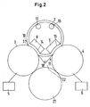
- FIG. 2 shows another embodiment of a calender, in the parts that correspond to those of FIG. 1 with are provided with the same reference numerals.
- the press directions are Wide nips 10, 11 at an angle of approximately 90 ° to one another.
- the two rollers 3, 4 and the jacket 7 are accordingly arranged like an inverted V.
- a sealing roller 21 is provided on the two rollers 3, 4 is present.
- a space 22 is delimited, in which a guide roller 18 is arranged. If the room 22 is sealed at the end, then it is possible to build up a vapor pressure in this room 22.
- This vapor pressure can be obtained either by external means generated, for example by feeding Steam in room 22.
- the steam pressure results usually more or less automatically after one short operating time in that steam from the web 2 escapes, which have been heated in the hotter Breitnip 10 is.
Landscapes
- Paper (AREA)
Abstract
Description
- Fig. 1
- eine schematische Ansicht eines Kalanders zum Glätten einer Papier- oder Kartonbahn und
- Fig. 2
- eine schematische Ansicht einer anderen Ausführungsform eines Kalanders.
Claims (14)
- Kalander zum Glätten einer Papier- oder Kartonbahn mit mindestens zwei Walzen, die mit einem gemeinsamen Mantel, der unter der Wirkung von Stützschuhen an den Walzen anliegt, eine der Anzahl der Walzen entsprechende Anzahl von Behandlungsnips bilden, dadurch gekennzeichnet, daß die Walzen (3, 4) mindestens zwei unterschiedliche Temperaturen aufweisen.
- Kalander nach Anspruch 1, dadurch gekennzeichnet, daß entlang eines Bahnlaufpfades zuerst eine heiße Walze (3) und dann eine kalte Walze (4) angeordnet ist.
- Kalander nach Anspruch 1 oder 2, dadurch gekennzeichnet, daß der Mantel (7) zwischen den Walzen (3, 4) angeordnet ist.
- Kalander nach Anspruch 3, dadurch gekennzeichnet, daß zwei Walzen (3, 4) mit Stützschuhen (8, 9) zusammenwirken, die eine entgegengesetzte Pressenrichtung aufweisen.
- Kalander nach einem der Ansprüche 1 bis 4, dadurch gekennzeichnet, daß die heiße Walze (3) eine Temperatur von mindestens 100°C und die kalte Walze (4) eine Temperatur von höchstens 60°C aufweist.
- Kalander nach Anspruch 5, dadurch gekennzeichnet, daß die Temperatur der heißen Walze (3) im Bereich von 150 bis 250°C und die Temperatur der kalten Walze (4) im Bereich von 30 bis 50°C liegt.
- Kalander nach einem der Ansprüche 1 bis 6, dadurch gekennzeichnet, daß der Bahnlaufpfad zwischen zwei Behandlungsnips (10, 11) mit einem Abstand zum Mantel (7) verläuft.
- Kalander nach einem der Ansprüche 1 bis 7, dadurch gekennzeichnet, daß die Bahn (2) auf der Oberfläche der Walzen (3, 4) aufliegt.
- Kalander nach einem der Ansprüche 1 bis 8, dadurch gekennzeichnet, daß zwei Walzen (3, 4) vorgesehen sind, die mit dem Mantel (7) zusammenwirken, wobei eine Dichtwalze (21) an beiden Walzen (3, 4) anliegt.
- Kalander nach Anspruch 9, dadurch gekennzeichnet, daß die beiden Walzen (3, 4), der Mantel (7) und die Dichtwalze (21) einen Raum (22) umgeben, in dem eine Leitwalze (18) angeordnet ist.
- Verfahren zum Glätten einer Papier- oder Kartonbahn, bei dem die Bahn durch mehrere Behandlungsnips geleitet wird, die zwischen einem gemeinsamen Mantel und einer der Anzahl der Behandlungsnips entsprechenden Anzahl von Walzen gebildet sind, wobei die Bahn in den Behandlungsnips mit Druck beaufschlagt wird, dadurch gekennzeichnet, daß die Bahn in mindestens zwei Behandlungsnips mit unterschiedlichen Temperaturen beaufschlagt wird.
- Verfahren nach Anspruch 11, dadurch gekennzeichnet, daß die Bahn zuerst beheizt und dann gekühlt wird.
- Verfahren nach Anspruch 11 oder 12, dadurch gekennzeichnet, daß man den Mantel zur thermischen Abschirmung zwischen den Walzen unterschiedlicher Temperatur verwendet.
- Verfahren nach Anspruch 12, dadurch gekennzeichnet, daß man die Bahn nach dem Beheizen durch einen geschlossenen Raum zum Kühlen führt.
Applications Claiming Priority (2)
| Application Number | Priority Date | Filing Date | Title |
|---|---|---|---|
| DE10157686 | 2001-11-24 | ||
| DE2001157686 DE10157686B4 (de) | 2001-11-24 | 2001-11-24 | Kalander und Verfahren zum Glätten einer Papier- oder Kartonbahn |
Publications (3)
| Publication Number | Publication Date |
|---|---|
| EP1318232A2 true EP1318232A2 (de) | 2003-06-11 |
| EP1318232A3 EP1318232A3 (de) | 2003-09-10 |
| EP1318232B1 EP1318232B1 (de) | 2006-06-28 |
Family
ID=7706840
Family Applications (1)
| Application Number | Title | Priority Date | Filing Date |
|---|---|---|---|
| EP20020024065 Expired - Lifetime EP1318232B1 (de) | 2001-11-24 | 2002-10-29 | Kalander und Verfahren zum Glätten einer Papier- oder Kartonbahn |
Country Status (2)
| Country | Link |
|---|---|
| EP (1) | EP1318232B1 (de) |
| DE (2) | DE10157686B4 (de) |
Family Cites Families (6)
| Publication number | Priority date | Publication date | Assignee | Title |
|---|---|---|---|---|
| GB1540056A (en) * | 1975-01-13 | 1979-02-07 | Wiggins Teape Ltd | Heat treatment of a web containing fibres of thermoplastic material |
| CH601686A5 (de) * | 1976-11-30 | 1978-07-14 | Escher Wyss Ag | |
| CA1249470A (en) * | 1985-01-08 | 1989-01-31 | Gregory L. Wedel | Electromagnetic extended nip press |
| FI74065C (fi) * | 1985-10-04 | 1987-12-10 | Waertsilae Oy Ab | Kalander, t.ex. superkalander. |
| US5439559A (en) * | 1994-02-14 | 1995-08-08 | Beloit Technologies | Heavy-weight high-temperature pressing apparatus |
| DE19828156A1 (de) * | 1998-06-24 | 1999-12-30 | Voith Sulzer Papiertech Patent | Vorrichtung zum Glätten einer Materialbahn |
-
2001
- 2001-11-24 DE DE2001157686 patent/DE10157686B4/de not_active Revoked
-
2002
- 2002-10-29 DE DE50207372T patent/DE50207372D1/de not_active Expired - Lifetime
- 2002-10-29 EP EP20020024065 patent/EP1318232B1/de not_active Expired - Lifetime
Also Published As
| Publication number | Publication date |
|---|---|
| DE10157686B4 (de) | 2005-11-17 |
| EP1318232A3 (de) | 2003-09-10 |
| DE50207372D1 (de) | 2006-08-10 |
| DE10157686A1 (de) | 2003-06-12 |
| EP1318232B1 (de) | 2006-06-28 |
Similar Documents
| Publication | Publication Date | Title |
|---|---|---|
| DE69517193T2 (de) | Vorrichtung zum trocknen und glätten einer faserbahn | |
| EP0967324A2 (de) | Vorrichtung zum Glätten einer Materialbahn | |
| EP1314819B1 (de) | Kalander und Verfahren zum Glätten einer Papier- oder Kartonbahn | |
| DE69703610T2 (de) | Verfahren zum kalendrieren einer papierbahn und kalender zur durchführung des verfahrens | |
| EP1318232B1 (de) | Kalander und Verfahren zum Glätten einer Papier- oder Kartonbahn | |
| EP1314820B1 (de) | Kalander zum Glätten einer Bahn aus Faserstoff | |
| EP1318234B1 (de) | Verfahren und Kalander zum Glätten einer Faserstoffbahn | |
| DE10206027C2 (de) | Kalander und Verfahren zum Glätten einer Faserstoffbahn | |
| DE60302777T2 (de) | Verfahren und Vorrichtung zur Kühlung eines sich bewegenden metallischen Bandes | |
| DE19822531B4 (de) | Kalanderwalze | |
| DE9306448U1 (de) | Glättwerksanordnung | |
| EP1314818B1 (de) | Vorrichtung und Verfahren zum Glätten einer Papier- oder Kartonbahn | |
| EP1314667B2 (de) | Verfahren zum Aufwickeln einer Papier- oder Kartonbahn | |
| EP1318236A2 (de) | Glättzylinderanordnung | |
| EP1424440B1 (de) | Bahnbehandlungsvorrichtung mit Befeuchtungseinrichtung | |
| DE10217910A1 (de) | Verfahren zum Behandeln einer Materialbahn und Kalander | |
| EP1369527B1 (de) | Kalenderanordnung und Verfahren zum Behandeln einer Materialbahn | |
| DE202006005604U1 (de) | Thermowalze | |
| EP0792965A1 (de) | Verfahren zum Satinieren von Papier und Kalander zur Durchführung des Verfahrens | |
| EP1318233B1 (de) | Verfahren und Vorrichtung zum Behandeln einer Faserstoffbahn | |
| DE10329198B4 (de) | Breitnip-Kalander | |
| EP1314821A2 (de) | Kalander und Verfahren zum Glätten einer Faserstoffbahn | |
| DE1966281A1 (de) | Stopfkraeuselvorrichtung | |
| DE102005021031A1 (de) | Kalanderanordnung | |
| EP2492394A1 (de) | Kalander |
Legal Events
| Date | Code | Title | Description |
|---|---|---|---|
| PUAI | Public reference made under article 153(3) epc to a published international application that has entered the european phase |
Free format text: ORIGINAL CODE: 0009012 |
|
| AK | Designated contracting states |
Designated state(s): AT BE BG CH CY CZ DE DK EE ES FI FR GB GR IE IT LI LU MC NL PT SE SK TR |
|
| AX | Request for extension of the european patent |
Extension state: AL LT LV MK RO SI |
|
| PUAL | Search report despatched |
Free format text: ORIGINAL CODE: 0009013 |
|
| AK | Designated contracting states |
Kind code of ref document: A3 Designated state(s): AT BE BG CH CY CZ DE DK EE ES FI FR GB GR IE IT LI LU MC NL PT SE SK TR |
|
| AX | Request for extension of the european patent |
Extension state: AL LT LV MK RO SI |
|
| 17P | Request for examination filed |
Effective date: 20030809 |
|
| AKX | Designation fees paid |
Designated state(s): DE FI SE |
|
| GRAP | Despatch of communication of intention to grant a patent |
Free format text: ORIGINAL CODE: EPIDOSNIGR1 |
|
| RTI1 | Title (correction) |
Free format text: CALENDER AND PAPER OR CARDBOARD WEB SMOOTHING PROCESS |
|
| GRAS | Grant fee paid |
Free format text: ORIGINAL CODE: EPIDOSNIGR3 |
|
| GRAA | (expected) grant |
Free format text: ORIGINAL CODE: 0009210 |
|
| AK | Designated contracting states |
Kind code of ref document: B1 Designated state(s): DE FI SE |
|
| REF | Corresponds to: |
Ref document number: 50207372 Country of ref document: DE Date of ref document: 20060810 Kind code of ref document: P |
|
| RAP2 | Party data changed (patent owner data changed or rights of a patent transferred) |
Owner name: VOITH PATENT GMBH |
|
| REG | Reference to a national code |
Ref country code: SE Ref legal event code: TRGR |
|
| PLBI | Opposition filed |
Free format text: ORIGINAL CODE: 0009260 |
|
| PLAX | Notice of opposition and request to file observation + time limit sent |
Free format text: ORIGINAL CODE: EPIDOSNOBS2 |
|
| 26 | Opposition filed |
Opponent name: ANDRITZ KUESTERS GMBH & CO. KG Effective date: 20070321 |
|
| PLBB | Reply of patent proprietor to notice(s) of opposition received |
Free format text: ORIGINAL CODE: EPIDOSNOBS3 |
|
| PLAB | Opposition data, opponent's data or that of the opponent's representative modified |
Free format text: ORIGINAL CODE: 0009299OPPO |
|
| R26 | Opposition filed (corrected) |
Opponent name: ANDRITZ KUESTERS GMBH Effective date: 20070321 |
|
| PGFP | Annual fee paid to national office [announced via postgrant information from national office to epo] |
Ref country code: SE Payment date: 20081014 Year of fee payment: 7 |
|
| EUG | Se: european patent has lapsed | ||
| PGFP | Annual fee paid to national office [announced via postgrant information from national office to epo] |
Ref country code: DE Payment date: 20101022 Year of fee payment: 9 |
|
| PG25 | Lapsed in a contracting state [announced via postgrant information from national office to epo] |
Ref country code: SE Free format text: LAPSE BECAUSE OF NON-PAYMENT OF DUE FEES Effective date: 20091030 |
|
| PGFP | Annual fee paid to national office [announced via postgrant information from national office to epo] |
Ref country code: FI Payment date: 20111013 Year of fee payment: 10 |
|
| PLBD | Termination of opposition procedure: decision despatched |
Free format text: ORIGINAL CODE: EPIDOSNOPC1 |
|
| PLBP | Opposition withdrawn |
Free format text: ORIGINAL CODE: 0009264 |
|
| PLBM | Termination of opposition procedure: date of legal effect published |
Free format text: ORIGINAL CODE: 0009276 |
|
| STAA | Information on the status of an ep patent application or granted ep patent |
Free format text: STATUS: OPPOSITION PROCEDURE CLOSED |
|
| 27C | Opposition proceedings terminated |
Effective date: 20121231 |
|
| PG25 | Lapsed in a contracting state [announced via postgrant information from national office to epo] |
Ref country code: DE Free format text: LAPSE BECAUSE OF NON-PAYMENT OF DUE FEES Effective date: 20130501 |
|
| REG | Reference to a national code |
Ref country code: DE Ref legal event code: R119 Ref document number: 50207372 Country of ref document: DE Effective date: 20130501 |
|
| PG25 | Lapsed in a contracting state [announced via postgrant information from national office to epo] |
Ref country code: FI Free format text: LAPSE BECAUSE OF NON-PAYMENT OF DUE FEES Effective date: 20121029 |