EP1317022A1 - Prise de courant à volets escamotables indépendants, notamment pour rasoirs électriques - Google Patents
Prise de courant à volets escamotables indépendants, notamment pour rasoirs électriques Download PDFInfo
- Publication number
- EP1317022A1 EP1317022A1 EP02292861A EP02292861A EP1317022A1 EP 1317022 A1 EP1317022 A1 EP 1317022A1 EP 02292861 A EP02292861 A EP 02292861A EP 02292861 A EP02292861 A EP 02292861A EP 1317022 A1 EP1317022 A1 EP 1317022A1
- Authority
- EP
- European Patent Office
- Prior art keywords
- retractable
- outlet according
- flap
- electric outlet
- electrical
- Prior art date
- Legal status (The legal status is an assumption and is not a legal conclusion. Google has not performed a legal analysis and makes no representation as to the accuracy of the status listed.)
- Granted
Links
- 238000000926 separation method Methods 0.000 claims abstract description 14
- 239000011810 insulating material Substances 0.000 claims description 5
- 239000004020 conductor Substances 0.000 claims description 4
- 230000006835 compression Effects 0.000 claims description 3
- 238000007906 compression Methods 0.000 claims description 3
- 230000000717 retained effect Effects 0.000 claims description 2
- 239000000463 material Substances 0.000 abstract description 2
- 238000007789 sealing Methods 0.000 description 4
- 230000008901 benefit Effects 0.000 description 3
- 238000002955 isolation Methods 0.000 description 3
- RYGMFSIKBFXOCR-UHFFFAOYSA-N Copper Chemical compound [Cu] RYGMFSIKBFXOCR-UHFFFAOYSA-N 0.000 description 1
- 229910052802 copper Inorganic materials 0.000 description 1
- 239000010949 copper Substances 0.000 description 1
- 230000009977 dual effect Effects 0.000 description 1
- 230000005611 electricity Effects 0.000 description 1
- 238000009413 insulation Methods 0.000 description 1
- 238000004519 manufacturing process Methods 0.000 description 1
- 229920003023 plastic Polymers 0.000 description 1
- 239000004033 plastic Substances 0.000 description 1
- XLYOFNOQVPJJNP-UHFFFAOYSA-N water Substances O XLYOFNOQVPJJNP-UHFFFAOYSA-N 0.000 description 1
Images



Classifications
-
- H—ELECTRICITY
- H01—ELECTRIC ELEMENTS
- H01R—ELECTRICALLY-CONDUCTIVE CONNECTIONS; STRUCTURAL ASSOCIATIONS OF A PLURALITY OF MUTUALLY-INSULATED ELECTRICAL CONNECTING ELEMENTS; COUPLING DEVICES; CURRENT COLLECTORS
- H01R13/00—Details of coupling devices of the kinds covered by groups H01R12/70 or H01R24/00 - H01R33/00
- H01R13/66—Structural association with built-in electrical component
- H01R13/70—Structural association with built-in electrical component with built-in switch
- H01R13/703—Structural association with built-in electrical component with built-in switch operated by engagement or disengagement of coupling parts, e.g. dual-continuity coupling part
- H01R13/7036—Structural association with built-in electrical component with built-in switch operated by engagement or disengagement of coupling parts, e.g. dual-continuity coupling part the switch being in series with coupling part, e.g. dead coupling, explosion proof coupling
-
- H—ELECTRICITY
- H01—ELECTRIC ELEMENTS
- H01R—ELECTRICALLY-CONDUCTIVE CONNECTIONS; STRUCTURAL ASSOCIATIONS OF A PLURALITY OF MUTUALLY-INSULATED ELECTRICAL CONNECTING ELEMENTS; COUPLING DEVICES; CURRENT COLLECTORS
- H01R13/00—Details of coupling devices of the kinds covered by groups H01R12/70 or H01R24/00 - H01R33/00
- H01R13/44—Means for preventing access to live contacts
- H01R13/447—Shutter or cover plate
- H01R13/453—Shutter or cover plate opened by engagement of counterpart
- H01R13/4534—Laterally sliding shutter
-
- H—ELECTRICITY
- H01—ELECTRIC ELEMENTS
- H01R—ELECTRICALLY-CONDUCTIVE CONNECTIONS; STRUCTURAL ASSOCIATIONS OF A PLURALITY OF MUTUALLY-INSULATED ELECTRICAL CONNECTING ELEMENTS; COUPLING DEVICES; CURRENT COLLECTORS
- H01R13/00—Details of coupling devices of the kinds covered by groups H01R12/70 or H01R24/00 - H01R33/00
- H01R13/66—Structural association with built-in electrical component
- H01R13/6608—Structural association with built-in electrical component with built-in single component
- H01R13/6633—Structural association with built-in electrical component with built-in single component with inductive component, e.g. transformer
Definitions
- a cover which covers the through holes of the socket and which must be lifted with one hand to insert the plug with the other hand when you want to connect this plug at the outlet.
- Such a cover guarantees the tightness of the socket as long that no plug is inserted into the socket.
- the present invention generally relates to a provision for ensuring the tightness of the aforementioned sockets, even after the introduction of files in them, and also leading to other benefits.
- a retractable flap made of insulating material associated with each of the through holes of the front part and designed to be able be actuated by an electrical contact pin in order to switch from one closed position, in which it covers the through hole it is in associated, in an open position when an electrical connection plug is introduced into the socket, and elastic return means urging in permanently each of the retractable flaps towards its position of closing, the retractable flaps being independent of each other by so that the unused female contact piece remains protected by a retractable flap occupying its closed position.
- the seal is obtained with as many flaps retractable independent that there are through holes and therefore pieces of female type contact.
- only two retractable flaps on three are used, depending on the voltage level chosen.
- the third unused always remains closed, which makes it possible to obtain, without cover, a tightness of the electrical outlet, both in the absence of a plug electrical connection and after inserting such a plug into the socket.
- the arrangement according to the invention lends itself advantageously to a development according to which the rear part comprises a housing containing an electrically connected separation transformer to female type contact parts and provided with two pins used for the energizing the transformer and extending towards the part front, while the face of the retractable flap protecting the contact part of the female type constituting the common terminal, and which is situated opposite the spikes, carries an elastic blade made of an electrically conductive material suitable for connect the two pins, so that the actuation of the flap carrying it during the introduction of a plug into the socket causes this blade until the entry contact with the two pins, causing the direct tensioning of the transformer.
- sockets of the aforementioned type can be equipped with a transformer to separate mains and user circuits to protect because of its isolation from the earth.
- the transformer was energized using several additional parts (cams, copper contact with rivet, ...) controlled by the introduction of the electrical contact pins of a plug electrical connection in female or cell type contact parts conductors of the power outlet.
- the tensioning of the transformer is done directly with a single simple piece (blade contact), low cost and easy to assemble, for the benefit of economical current with greater reliability.
- the flap carrying the blade elastic thus has a double function, namely the sealing of the grip current and energizing the transformer.
- the means return elastics preferably include intervening springs each in compression between a retractable flap and a side wall of the housing of the front part.
- the socket outlet according to the invention further comprises a plate which extends between the contact parts of female type and retractable flaps and which includes means for guiding in translation of these flaps.
- This plate thus makes it possible to perfect the guidance of the flaps retractable while helping to maintain them in the housing of the front part.
- the wafer thus used according to the invention can also advantageously assume other functions.
- It can, for example, include a housing cavity of the elastic blade, the bottom of which is pierced with two through holes for both separation transformer pins.
- the elastic blade can thus move on the bottom of this cavity, which contributes to the proper functioning of the sealing system separation transformer voltage.
- the cavity of the wafer preferably includes at least one slot for receiving the retaining studs of the elastic blade on its support flap and guiding in translation of these studs.
- the brochure may also present, to the right of the female type contact, recesses which give access to these parts of contact.
- it further comprises, advantageously, in the extension of these recesses, projecting from its face arranged opposite the rear part, consoles provided to guide the contact pins connection plug.
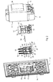
- the power outlet 10 comprises, in a manner known per se, a body 11 in insulating material formed by a front part 11 and a rear part 13 fixed to the front part 12 by screwing.
- the front part 12 is provided three holes 14, 14 ', 14 "for the passage of electrical contact pins electrical connection plugs, while the rear part 13 is provided with three female type contact parts respectively located opposite the holes 14, 14 ', 14 "made in the front part 12.
- the three contact pieces 16 are each suitable for receiving a electrical contact pin and together form the terminals of one and the same dual voltage electrical circuit, one of them constituting a common terminal at both voltage values.
- the socket 10 being, more precisely, intended for receive the plug pins of electric shavers, these values are, after connection of socket 10 to the mains electric current distribution, equal to 110 V and 230 V.
- the rear part 13 comprises a housing 17 containing a separation transformer 18 electrically connected to the contact parts 16 of the female type and which is intended to be connected to the distribution network of the electric current via two terminals 19.
- each of the through holes 14, 14 ', 14 presents a particular configuration which allows the taking of current 10 to receive electrical contact pins of different standards.
- a retractable flap 20, 20 ′, 20 "made of material insulation is associated with each of these holes 14, 14 ', 14 "of the front part 12 and is designed to be able to be actuated by an electrical contact pin view from a closed position, in which it covers the hole with which it is associated, in an open position when a electrical connection is inserted into the socket 10.
- retractable flaps 20, 20 ', 20 are independent of each other so that the unused contact part 16 remains protected by a retractable flap 20, 20 ', 20 "occupying its position closing.
- elastic return means permanently urge each of the retractable flaps 20, 20 ', 20 "towards its closed position.
- the front part 12 also includes a housing 21 having a bottom 22 in which the through holes 14, 14 ', 14 "are drilled, according to a horizontal alignment.
- the retractable flaps 20, 20 ', 20 are mounted movable in translation in this housing 21, parallel to one another and to the bottom 22.
- the housing 21 extends towards the front of the front part 12 and its bottom 22 is located at the front end of the latter, while the retractable flaps 20, 20 ′, 20 "interposed on the access to the contact parts 16 are arranged between this bottom and the rear part 13.
- each flap retractable 20, 20 ', 20 is formed by a tab 23, 23', 23" finished longitudinally by an actuating heel 24, 24 ', 24 "which extends beyond the plane the tongue 23, 23 ', 23 ", the front and rear sides thereof, and on which is formed, as is best seen in Figures 7 to 10, one side inclined 25, 25 ', 25 "which extends obliquely to the plane of the tongue 23, 23 ', 23 ".
- each inclined face 25, 25 ', 25 " is located opposite the hole 14, 14', 14" with which the flap is associated retractable 20, 20 ', 20 “on which it is formed, to generate the translation of the latter in response to a thrust exerted by a contact pin connection plug.
- the bottom 22 of the housing 21 has a recess 26 which receives the portion of the heels 24, 24 ', 24 " extending beyond the plane of the tongue 23, 23 ′, 23 "on the front side of the flap retractable 20, 20 ', 20 ".
- the housing 21 of the front part 12 further comprises means for guiding in translation the retractable flaps 20, 20 ′, 20 ".
- these guide means include ribs 27 parallel, projecting from the bottom 22 of the housing 21, between the retractable shutters 20, 20 ', 20 ", and studs 28 projecting from the two walls lateral 29 of the housing 21 extending parallel to the retractable flaps 20, 20 ', 20 ".
- the elastic means return springs 30 each intervening in compression between a retractable flap 20, 20 ′, 20 "and a side wall 29 of the housing 21 of the front part 12, which extends transversely to the direction of movement of these retractable flaps 20, 20 ', 20 ".
- each of the springs 30 is housed in a longitudinal recess 31 made in the bottom 22 of the housing 21 of the front part 12.
- each retractable flap 20, 20 ′, 20 “comprises a lug 32, 32 ', 32 "at its longitudinal end opposite to that having the inclined face 25, 25 ', 25 “and forming a seat for one of the ends of the spring 30 associated with this retractable flap 20, 20 ′, 20 ".
- the side wall 29 of the housing 21 which extends transversely to the direction of movement of the retractable flaps 20, 20 ', 20 "and in front of these, includes, for each spring 30, a pair of bosses arranged face to face and shaped so as to enclose a end of this spring 30 in order to secure it to the housing 21.
- each of the bosses is generally wedge-shaped.
- a front plate 34 (see Figures 2 and 3), not shown in the Figure 1, is intended to cover the front face 35 of the front part 12 of the socket current 10.
- This front faceplate 34 is shaped so that it can be fitted on the front part 12 and has a passage opening for the housing 21.
- the face of the bottom 22 located outside the housing 21 is thus flush with the front face of the front faceplate 34.
- two available pins 36 of the transformer 18, which extend in the direction of the front part 12, are used for energizing this transformer 18 (see Figures 11 and 12), while the rear face 37 of the flap retractable 20 'protecting the contact part 16 of the female type constituting the common terminal (the central flap in the case of the embodiment shown), carries an elastic blade 38 of conductive material electricity, suitable for electrically connecting the two pins 36, so that actuation of the flap 20 'carrying it, during the introduction of a electrical connection in the socket 10, drives this blade elastic 38 until it comes into contact with the two pins 36, causing the direct switching on of the isolation transformer 18.
- transformer 18 serves in particular to separate the mains and user circuits to protect the latter from made of its isolation from the earth.
- This elastic blade 38 is retained on the retractable flap 20 ' by means of two pairs of studs 39 spaced from one another.
- the two pairs of studs 39 are, moreover, connected to one another by a central rib 40 also erected on the face 37 and on which the elastic blade 38.
- the shutters 20 and 20 "located on either side of the central shutter 20 ' each have, in turn, a longitudinal notch 41, 41 "specific to each receive a pin 36 from the separation transformer 18, so that this pin 36 does not hinder the movement of the retractable flap 20, 20 " corresponding.
- the ribs 27 of the housing 21 also contribute to the support and to the guide of the elastic blade 38.
- the electrical outlet 10 further comprises a plate 42 which extends between the female type contact parts 16 and the flaps retractable 20, 20 ', 20 "and which includes guide means in translation of these flaps 20, 20 ', 20 ".
- this plate 42 extends substantially at level with the opening of the housing 21 of the front part 12, at the interface between the latter and the rear part 13.
- these guide means include bars 43 extending parallel to each other and on both sides of recesses 44 formed in the plate 42, in line with the contact parts 16 female type.
- the plate 42 has also, in the extension of the recesses 44, projecting on its face 45 arranged opposite the rear part 13, consoles 46 provided to guide the electrical contact pins of the connection plug.
- This plate 42 further comprises a housing cavity 47 of the elastic blade 38, the bottom 48 of which is pierced with two through holes 49 pins 36 of the separation transformer 18.
- This cavity 47 further comprises two receiving slots 50 pads 39 for retaining the elastic blade 38 on its support flap 20 ′ and guiding in translation of these studs 39.
- the plate 42 thus ensures, by itself, the plurality of functions defined above.
- the subassembly is first assembled consisting of the front part 12 and the flaps 20, 20 ', 20 ", with setting in place of the springs 30 and of the elastic blade 38.
- the third component remains in its position of closing and thus protects the unused contact part 16.
- the actuation of the flap 20 ' also drives the blade elastic contact 38 in the direction of the pins 36 of the separation transformer 18.
- the springs 30 constituting the elastic return means systematically bring the flaps back to their closed position.
Landscapes
- Engineering & Computer Science (AREA)
- Power Engineering (AREA)
- Connector Housings Or Holding Contact Members (AREA)
- Details Of Connecting Devices For Male And Female Coupling (AREA)
- Dry Shavers And Clippers (AREA)
- Electromechanical Clocks (AREA)
- Professional, Industrial, Or Sporting Protective Garments (AREA)
- Outer Garments And Coats (AREA)
Abstract
Description
- une partie avant dotée de trois trous de passage de broches de contact électrique de fiches de raccordement électrique, et
- une partie arrière dotée de trois pièces de contact de type femelle respectivement situées en regard des trous ménagés dans la partie avant, propres chacune à recevoir une broche de contact électrique et formant les bornes d'un seul et même circuit électrique bi-tension, l'une d'entre-elles constituant une borne commune aux deux valeurs de tension.
- la figure 1 est une vue en perspective d'une prise de courant suivant l'invention ;
- la figure 2 en est une vue en perspective éclatée ;
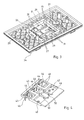
- les figures 3 et 4 sont des vues en perspective de la partie avant et de la plaquette que comporte cette prise de courant ;
- la figure 5 est une vue partielle en perspective de cette partie avant, illustrant le logement de cette dernière, équipé des volets escamotables et des ressorts de rappel visibles sur la figure 2 ;
- la figure 6 est une vue partielle en coupe longitudinale de la partie avant de la prise de courant, suivant la ligne VI-VI de la figure 1 ;
- les figures 7 et 8 sont respectivement des vues en perspective et en coupe médiane longitudinale du volet escamotable central de la figure 2 ;
- les figures 9 et 10 sont respectivement des vues en perspective et en coupe médiane longitudinale du volet escamotable droit de la figure 2 ; et
- les figures 11 et 12 sont des vues en perspective illustrant, de façon très schématique, la mise sous tension du transformateur de séparation.
Claims (22)
- Prise de courant électrique (10) comportant un corps (11) en matériau isolant, ayant:et caractérisée par un volet escamotable (20, 20', 20") en matériau isolant associé à chacun des trous (14, 14', 14") de la partie avant (12) et conçu pour pouvoir être actionné par une broche (52) de contact électrique en vue de passer d'une position de fermeture, dans laquelle il recouvre le trou (14), 14', 14") auquel il est associé, à une position d'ouverture lorsqu'une fiche (51) de raccordement électrique est introduite dans la prise (10), et des moyens (30) élastiques de rappel sollicitant en permanence chacun des volets escamotables (20, 20', 20") en direction de sa position de fermeture, les volets escamotables (20, 20', 20") étant indépendants les uns des autres en sorte que la pièce de contact (16) inutilisée reste protégée par un volet (20, 20', 20") occupant sa position de fermeture.une partie avant (12) dotée de trois trous (14, 14', 14") de passage de broches (52) de contact électrique de fiches (51) de raccordement électrique,une partie arrière (13) dotée de trois pièces de contact (16) de type femelle respectivement situées en regard des trous (14, 14', 14") ménagés dans la partie avant (12), propres chacune à recevoir une broche (52) de contact électrique et formant ensemble les bornes d'un seul et même circuit électrique bi-tension, l'une d'entre elles constituant une borne commune aux deux valeurs de tension,
- Prise de courant électrique selon la revendication 1, caractérisée en ce que la partie avant comporte un logement (21) ayant un fond dans lequel sont percés lesdits trous (14, 14', 14"), suivant un alignement horizontal, et à la faveur duquel les volets escamotables (20, 20', 20") sont montés mobiles en translation sur la partie avant, parallèlement l'un à l'autre et au fond (22).
- Prise de courant électrique selon la revendication 2, caractérisée en ce que le logement (21) s'étend vers l'avant de la partie avant (12) et son fond (22) est situé à l'extrémité avant de cette dernière, tandis que les volets escamotables (20, 20', 20"), interposés sur l'accès aux pièces de contact (16), sont disposés entre le fond (22) et la partie arrière (13).
- Prise de courant électrique selon la revendication 2 ou 3, caractérisée en ce que la partie arrière (13) comporte un logement (17) contenant un transformateur de séparation (18) relié électriquement aux pièces de contact (16) de type femelle et pourvu de deux picots (36) s'étendant en direction de la partie avant et qui sont utilisés pour la mise sous tension du transformateur (18), tandis que la face (37) du volet escamotable (20') protégeant la pièce de contact de type femelle constituant la borne commune, et qui est située en regard des picots (36), porte une lame élastique (38) en matériau conducteur de l'électricité propre à relier électriquement les deux picots (36), en sorte que l'actionnement du volet (20') la portant, lors de l'introduction d'une fiche (51) dans la prise (10), entraíne cette lame (38) jusqu'à l'entrée en contact avec les deux picots (36), provoquant la mise sous tension directe du transformateur (18).
- Prise de courant électrique selon la revendication 4, caractérisée en ce que les volets (20, 20") situés de part et d'autre de celui portant la lame élastique (38) présentent chacun une encoche longitudinale (41', 41") propre à recevoir un des picots (36) du transformateur de séparation (18) de façon que le picot (36) ne gêne pas le mouvement du volet escamotable (20, 20") correspondant.
- Prise de courant électrique selon la revendication 4 ou 5, caractérisée en ce que la lame élastique (28) est retenue sur le volet la portant par des plots (39) dressés sur ce volet (20') et pinçant cette lame (38).
- Prise de courant électrique selon l'une quelconque des revendications 1 à 6, caractérisée en ce que chaque volet comporte une face inclinée (25, 25', 25") située en regard du trou de passage (14, 14', 14") auquel est associé le volet escamotable (20, 20', 20"), pour générer la translation de ce dernier en réponse à une poussée exercée par une broche de contact électrique (52).
- Prise de courant électrique selon la revendication 7, caractérisée en ce que chaque volet escamotable (20, 20', 20") est formé d'une languette (23, 23', 23") terminée longitudinalement par un talon d'actionnement 24, 24', 24") qui déborde le plan de la languette (23, 23', 23"), des côtés avant et arrière de celle-ci, et sur lequel est formée ladite face inclinée (25, 25', 25"), qui s'étend en oblique par rapport au plan de la languette (23, 23', 23").
- Prise de courant électrique selon les revendications 2 et 8 prise conjointement, caractérisée en ce que le fond (21) comporte un décrochement (26) recevant la partie du talon (24, 24', 24") qui déborde le plan de la languette (23, 23', 23") du volet escamotable (20, 20', 20"), du côté avant de celui-ci.
- Prise de courant électrique selon l'une quelconque des revendications 1 à 9, caractérisée en ce qu'elle comporte, en outre, une plaquette qui s'étend entre les pièces de contact (16) de type femelle et les volets escamotables (20, 20', 20") et qui comporte des moyens de guidage en translation de ces volets.
- Prise de courant électrique selon les revendications 4 et 10 prises conjointement, caractérisée en ce que la plaquette (42) comporte une cavité (47) de logement de la lame élastique (38), dont le fond (48) est percé de deux trous (49) de passage des deux picots du transformateur de séparation (18).
- Prise de courant électrique selon les revendications 6 et 11 prises conjointement, caractérisée en ce que la cavité (47) de la plaquette (42) comporte au moins une fente (50) de réception des plots (39) de retenue de la lame élastique (38) sur son volet de support (20') et de guidage en translation de ces plots (39).
- Prise de courant électrique selon l'une quelconque des revendications 10 à 12, caractérisée en ce que la plaquette (42) présente, au droit des pièces de contact (16) de type femelle, des évidements (44) qui donnent accès à ces pièces de contact.
- Prise de courant électrique selon la revendication 13, caractérisée en ce que la plaquette (42) présente, dans le prolongement des évidements (44), en saillie sur sa face (45) disposée en regard de la partie arrière (13), des consoles (46) prévues pour guider les broches de contact électrique (52) de la fiche (51) de raccordement.
- Prise de courant électrique selon la revendication 8 et l'une quelconque des revendications 10 à 14, caractérisée en ce que les moyens de guidage prévus sur la plaquette comportent des barrettes (43) s'étendant parallèlement l'une à l'autre et de part et d'autre des évidements (44), et conçues pour guider la partie des volets escamotables (20, 20', 20") débordant du plan de la languette (23, 23', 23") du volet (20, 20', 20"), à l'arrière de celui-ci.
- Prise de courant électrique selon l'une quelconque des revendications 2 à 15, caractérisée en ce que les moyens élastiques de rappel comportent des ressorts (30) intervenant chacun en compression entre un volet escamotable (20, 20', 20") et une paroi latérale (29) du logement (21) de la partie avant (12), qui s'étend transversalement à la direction de déplacement des volets escamotables (20, 20', 20").
- Prise de courant électrique selon la revendication 16, caractérisée en ce que chacun des ressorts (30) est logé dans une creusure longitudinale (31) pratiquée dans le fond (22) du logement (21) de la partie avant (12).
- Prise de courant électrique selon la revendication 16 ou 17, caractérisée en ce que chaque volet escamotable (20, 20', 20") comporte un ergot (32, 32', 32") à son extrémité longitudinale opposée à celle présentant ladite face inclinée (25, 25', 25") et formant un siège pour l'une des extrémités du ressort (30) associé à ce volet escamotable.
- Prise de courant électrique selon la revendication 18, caractérisée en ce que l'une des parois latérales du logement (21) de la partie avant (12), transversale à la direction du déplacement des volets escamotables (20, 20', 20"), comporte, pour chaque ressort (30), une paire de bossages (33) disposés face à face et conformés de manière à enserrer une extrémité de ce ressort (30) en vue de l'assujettir au logement (21).
- Prise de courant électrique selon l'une quelconque des revendications 2 à 19, caractérisée en ce que le logement (21) de la partie avant (12) comporte des moyens de guidage en translation des volets escamotables (20, 20', 20").
- Prise de courant électrique selon la revendication 20, caractérisée en ce que les moyens de guidage en translation comportent des nervures (27) parallèles, faisant saillie du fond (22) du logement (21), entre les volets escamotables (20), 20', 20") et des plots (28) en saillie sur les deux parois latérales (29) du logement (21) s'étendant parallèlement aux volets escamotables (20, 20', 20").
- Prise de courant électrique selon l'une quelconque des revendications 1 à 21, caractérisée en ce que les pièces de contact (16) de type femelle et les trous de passage (14, 14', 14") sont conçus pour recevoir les broches de fiches de raccordement de rasoirs électriques.
Applications Claiming Priority (2)
| Application Number | Priority Date | Filing Date | Title |
|---|---|---|---|
| FR0115258 | 2001-11-26 | ||
| FR0115258A FR2832864B1 (fr) | 2001-11-26 | 2001-11-26 | Prise de courant a volets escamotables independants, notamment pour rasoirs electriques |
Publications (2)
| Publication Number | Publication Date |
|---|---|
| EP1317022A1 true EP1317022A1 (fr) | 2003-06-04 |
| EP1317022B1 EP1317022B1 (fr) | 2006-02-01 |
Family
ID=8869782
Family Applications (1)
| Application Number | Title | Priority Date | Filing Date |
|---|---|---|---|
| EP02292861A Expired - Lifetime EP1317022B1 (fr) | 2001-11-26 | 2002-11-18 | Prise de courant à volets escamotables indépendants, notamment pour rasoirs électriques |
Country Status (6)
| Country | Link |
|---|---|
| EP (1) | EP1317022B1 (fr) |
| CN (1) | CN100466390C (fr) |
| AT (1) | ATE317159T1 (fr) |
| DE (1) | DE60208988T2 (fr) |
| ES (1) | ES2253504T3 (fr) |
| FR (1) | FR2832864B1 (fr) |
Cited By (2)
| Publication number | Priority date | Publication date | Assignee | Title |
|---|---|---|---|---|
| EP1930996A1 (fr) * | 2006-12-08 | 2008-06-11 | Electrolux Home Products Corporation N.V. | Dispositif de sécurité pour fours domestiques |
| CN101976776A (zh) * | 2010-07-01 | 2011-02-16 | 浙江正泰建筑电器有限公司 | 双电压双功率单相两极安全插座 |
Families Citing this family (1)
| Publication number | Priority date | Publication date | Assignee | Title |
|---|---|---|---|---|
| CN110289153B (zh) * | 2019-06-12 | 2025-03-21 | 广东拉斐电气有限公司 | 一种刮须插座 |
Citations (3)
| Publication number | Priority date | Publication date | Assignee | Title |
|---|---|---|---|---|
| GB719500A (en) * | 1952-06-12 | 1954-12-01 | Alexander Reginald Ward | Improvements in and relating to electrical connector fitments |
| DE1490638A1 (de) * | 1964-08-29 | 1969-09-04 | Siemens Ag | Sicherheitssteckvorrichtung |
| GB1445055A (en) * | 1974-05-14 | 1976-08-04 | Gen Electric Co Ltd | Electric socket connectors |
-
2001
- 2001-11-26 FR FR0115258A patent/FR2832864B1/fr not_active Expired - Fee Related
-
2002
- 2002-11-18 EP EP02292861A patent/EP1317022B1/fr not_active Expired - Lifetime
- 2002-11-18 DE DE60208988T patent/DE60208988T2/de not_active Expired - Lifetime
- 2002-11-18 AT AT02292861T patent/ATE317159T1/de not_active IP Right Cessation
- 2002-11-18 ES ES02292861T patent/ES2253504T3/es not_active Expired - Lifetime
- 2002-11-26 CN CNB021528861A patent/CN100466390C/zh not_active Expired - Fee Related
Patent Citations (3)
| Publication number | Priority date | Publication date | Assignee | Title |
|---|---|---|---|---|
| GB719500A (en) * | 1952-06-12 | 1954-12-01 | Alexander Reginald Ward | Improvements in and relating to electrical connector fitments |
| DE1490638A1 (de) * | 1964-08-29 | 1969-09-04 | Siemens Ag | Sicherheitssteckvorrichtung |
| GB1445055A (en) * | 1974-05-14 | 1976-08-04 | Gen Electric Co Ltd | Electric socket connectors |
Cited By (3)
| Publication number | Priority date | Publication date | Assignee | Title |
|---|---|---|---|---|
| EP1930996A1 (fr) * | 2006-12-08 | 2008-06-11 | Electrolux Home Products Corporation N.V. | Dispositif de sécurité pour fours domestiques |
| CN101976776A (zh) * | 2010-07-01 | 2011-02-16 | 浙江正泰建筑电器有限公司 | 双电压双功率单相两极安全插座 |
| CN101976776B (zh) * | 2010-07-01 | 2012-11-28 | 浙江正泰建筑电器有限公司 | 双电压双功率单相两极安全插座 |
Also Published As
| Publication number | Publication date |
|---|---|
| FR2832864B1 (fr) | 2007-01-19 |
| CN1421960A (zh) | 2003-06-04 |
| EP1317022B1 (fr) | 2006-02-01 |
| DE60208988T2 (de) | 2006-08-17 |
| DE60208988D1 (de) | 2006-04-13 |
| ES2253504T3 (es) | 2006-06-01 |
| FR2832864A1 (fr) | 2003-05-30 |
| ATE317159T1 (de) | 2006-02-15 |
| CN100466390C (zh) | 2009-03-04 |
Similar Documents
| Publication | Publication Date | Title |
|---|---|---|
| FR3084781A1 (fr) | Support d’appareillage electrique et appareillage electrique associe | |
| FR2702889A1 (fr) | Connecteur électrique . | |
| FR2967829A1 (fr) | Prise electrique comportant des montants lateraux mobiles en translation | |
| EP1317022B1 (fr) | Prise de courant à volets escamotables indépendants, notamment pour rasoirs électriques | |
| EP1881560B1 (fr) | Appareil électrique comportant une borne de connexion bilatérale | |
| FR2524721A1 (fr) | Bornier de raccordement pour fils electriques | |
| FR3077915A1 (fr) | Bloc d'eclairage de securite configurable | |
| EP1100105A1 (fr) | Dispositif de précâblage pour contacteurs | |
| EP4078641B1 (fr) | Mecanisme pour un commutateur electrique,ensemble electrique et commutateur electrique associes | |
| EP1608039A1 (fr) | Borne de connexion auto-dénudante et appareillage éléctrique équipé d'une telle borne | |
| FR2876508A1 (fr) | Prise de courant avec obturateur de surete et bati multifonctionnel | |
| EP0660461A1 (fr) | Socle multiple pour prise de courant | |
| EP3605750B1 (fr) | Mécanisme d'appareillage électrique et appareillage électrique associé | |
| FR2725312A1 (fr) | Assemblage de connecteur electrique pour telecommunications | |
| EP3840136A1 (fr) | Mecanisme d'appareillage lectrique,ensemble electrique et appareillage electrique associes | |
| EP4243219B1 (fr) | Prise de courant selon un standard avec contacts de terre latéraux à sécurité renforcée | |
| FR2907604A1 (fr) | Prise electrique. | |
| FR2748977A1 (fr) | Motoreducteur pour essuie-glace et organe de connexion associe | |
| EP0033675A1 (fr) | Dispositif électrique comportant un porte-fusible de sécurité | |
| EP3840002B1 (fr) | Enjoliveur et commutateur électrique comprenant un tel enjoliveur | |
| FR2995147A1 (fr) | Prise electrique comportant des moyens de commande electrique | |
| FR2945893A1 (fr) | Prise de courant comportant un obturateur verrouillable | |
| EP1199779B1 (fr) | Connecteur électrique pour appareillage électrique à lames métalliques de connection et système électrique comprenant de tels appareillage et connecteur électriques | |
| EP3457497A1 (fr) | Contacteur électrique avec un bouton poussoir pour ouvrir le ressort de serrage d'une borne de connexion push-in | |
| EP0488896B1 (fr) | Fiche électrique à double isolation |
Legal Events
| Date | Code | Title | Description |
|---|---|---|---|
| PUAI | Public reference made under article 153(3) epc to a published international application that has entered the european phase |
Free format text: ORIGINAL CODE: 0009012 |
|
| AK | Designated contracting states |
Designated state(s): AT BE BG CH CY CZ DE DK EE ES FI FR GB GR IE IT LI LU MC NL PT SE SK TR |
|
| AX | Request for extension of the european patent |
Extension state: AL LT LV MK RO SI |
|
| RIN1 | Information on inventor provided before grant (corrected) |
Inventor name: JUVING, FRANK |
|
| 17P | Request for examination filed |
Effective date: 20031001 |
|
| 17Q | First examination report despatched |
Effective date: 20031223 |
|
| AKX | Designation fees paid |
Designated state(s): AT DE ES GB IT |
|
| GRAP | Despatch of communication of intention to grant a patent |
Free format text: ORIGINAL CODE: EPIDOSNIGR1 |
|
| GRAS | Grant fee paid |
Free format text: ORIGINAL CODE: EPIDOSNIGR3 |
|
| GRAA | (expected) grant |
Free format text: ORIGINAL CODE: 0009210 |
|
| AK | Designated contracting states |
Kind code of ref document: B1 Designated state(s): AT DE ES GB IT |
|
| PG25 | Lapsed in a contracting state [announced via postgrant information from national office to epo] |
Ref country code: IT Free format text: LAPSE BECAUSE OF FAILURE TO SUBMIT A TRANSLATION OF THE DESCRIPTION OR TO PAY THE FEE WITHIN THE PRESCRIBED TIME-LIMIT;WARNING: LAPSES OF ITALIAN PATENTS WITH EFFECTIVE DATE BEFORE 2007 MAY HAVE OCCURRED AT ANY TIME BEFORE 2007. THE CORRECT EFFECTIVE DATE MAY BE DIFFERENT FROM THE ONE RECORDED. Effective date: 20060201 |
|
| REG | Reference to a national code |
Ref country code: GB Ref legal event code: FG4D Free format text: NOT ENGLISH |
|
| REF | Corresponds to: |
Ref document number: 60208988 Country of ref document: DE Date of ref document: 20060413 Kind code of ref document: P |
|
| GBT | Gb: translation of ep patent filed (gb section 77(6)(a)/1977) |
Effective date: 20060413 |
|
| REG | Reference to a national code |
Ref country code: ES Ref legal event code: FG2A Ref document number: 2253504 Country of ref document: ES Kind code of ref document: T3 |
|
| PLBE | No opposition filed within time limit |
Free format text: ORIGINAL CODE: 0009261 |
|
| STAA | Information on the status of an ep patent application or granted ep patent |
Free format text: STATUS: NO OPPOSITION FILED WITHIN TIME LIMIT |
|
| 26N | No opposition filed |
Effective date: 20061103 |
|
| PGFP | Annual fee paid to national office [announced via postgrant information from national office to epo] |
Ref country code: AT Payment date: 20081124 Year of fee payment: 7 |
|
| PG25 | Lapsed in a contracting state [announced via postgrant information from national office to epo] |
Ref country code: AT Free format text: LAPSE BECAUSE OF NON-PAYMENT OF DUE FEES Effective date: 20091118 |
|
| PGFP | Annual fee paid to national office [announced via postgrant information from national office to epo] |
Ref country code: GB Payment date: 20131121 Year of fee payment: 12 Ref country code: DE Payment date: 20131106 Year of fee payment: 12 |
|
| PGFP | Annual fee paid to national office [announced via postgrant information from national office to epo] |
Ref country code: IT Payment date: 20131118 Year of fee payment: 12 Ref country code: ES Payment date: 20131017 Year of fee payment: 12 |
|
| REG | Reference to a national code |
Ref country code: DE Ref legal event code: R119 Ref document number: 60208988 Country of ref document: DE |
|
| GBPC | Gb: european patent ceased through non-payment of renewal fee |
Effective date: 20141118 |
|
| PG25 | Lapsed in a contracting state [announced via postgrant information from national office to epo] |
Ref country code: GB Free format text: LAPSE BECAUSE OF NON-PAYMENT OF DUE FEES Effective date: 20141118 Ref country code: DE Free format text: LAPSE BECAUSE OF NON-PAYMENT OF DUE FEES Effective date: 20150602 |
|
| PG25 | Lapsed in a contracting state [announced via postgrant information from national office to epo] |
Ref country code: IT Free format text: LAPSE BECAUSE OF NON-PAYMENT OF DUE FEES Effective date: 20141118 |
|
| REG | Reference to a national code |
Ref country code: ES Ref legal event code: FD2A Effective date: 20160506 |
|
| PG25 | Lapsed in a contracting state [announced via postgrant information from national office to epo] |
Ref country code: ES Free format text: LAPSE BECAUSE OF NON-PAYMENT OF DUE FEES Effective date: 20141119 |