EP1316915B1 - Hologram comportant une information d'authentification enregistrée dans celui-ci - Google Patents
Hologram comportant une information d'authentification enregistrée dans celui-ci Download PDFInfo
- Publication number
- EP1316915B1 EP1316915B1 EP02026883A EP02026883A EP1316915B1 EP 1316915 B1 EP1316915 B1 EP 1316915B1 EP 02026883 A EP02026883 A EP 02026883A EP 02026883 A EP02026883 A EP 02026883A EP 1316915 B1 EP1316915 B1 EP 1316915B1
- Authority
- EP
- European Patent Office
- Prior art keywords
- hologram
- minute object
- authenticating information
- shielding block
- minute
- Prior art date
- Legal status (The legal status is an assumption and is not a legal conclusion. Google has not performed a legal analysis and makes no representation as to the accuracy of the status listed.)
- Expired - Lifetime
Links
- 238000005286 illumination Methods 0.000 claims description 16
- 230000005855 radiation Effects 0.000 claims description 12
- 230000003287 optical effect Effects 0.000 claims description 11
- 238000000034 method Methods 0.000 description 8
- 238000001093 holography Methods 0.000 description 5
- 238000004519 manufacturing process Methods 0.000 description 3
- 230000000007 visual effect Effects 0.000 description 3
- 238000010276 construction Methods 0.000 description 2
- 230000000694 effects Effects 0.000 description 2
- 230000001678 irradiating effect Effects 0.000 description 2
- 238000005070 sampling Methods 0.000 description 2
- 230000015572 biosynthetic process Effects 0.000 description 1
- 238000001459 lithography Methods 0.000 description 1
- 230000009467 reduction Effects 0.000 description 1
- 230000004256 retinal image Effects 0.000 description 1
Images


Classifications
-
- G—PHYSICS
- G03—PHOTOGRAPHY; CINEMATOGRAPHY; ANALOGOUS TECHNIQUES USING WAVES OTHER THAN OPTICAL WAVES; ELECTROGRAPHY; HOLOGRAPHY
- G03H—HOLOGRAPHIC PROCESSES OR APPARATUS
- G03H1/00—Holographic processes or apparatus using light, infrared or ultraviolet waves for obtaining holograms or for obtaining an image from them; Details peculiar thereto
- G03H1/04—Processes or apparatus for producing holograms
- G03H1/08—Synthesising holograms, i.e. holograms synthesized from objects or objects from holograms
-
- G—PHYSICS
- G03—PHOTOGRAPHY; CINEMATOGRAPHY; ANALOGOUS TECHNIQUES USING WAVES OTHER THAN OPTICAL WAVES; ELECTROGRAPHY; HOLOGRAPHY
- G03H—HOLOGRAPHIC PROCESSES OR APPARATUS
- G03H1/00—Holographic processes or apparatus using light, infrared or ultraviolet waves for obtaining holograms or for obtaining an image from them; Details peculiar thereto
-
- G—PHYSICS
- G06—COMPUTING; CALCULATING OR COUNTING
- G06K—GRAPHICAL DATA READING; PRESENTATION OF DATA; RECORD CARRIERS; HANDLING RECORD CARRIERS
- G06K19/00—Record carriers for use with machines and with at least a part designed to carry digital markings
- G06K19/06—Record carriers for use with machines and with at least a part designed to carry digital markings characterised by the kind of the digital marking, e.g. shape, nature, code
- G06K19/08—Record carriers for use with machines and with at least a part designed to carry digital markings characterised by the kind of the digital marking, e.g. shape, nature, code using markings of different kinds or more than one marking of the same kind in the same record carrier, e.g. one marking being sensed by optical and the other by magnetic means
- G06K19/10—Record carriers for use with machines and with at least a part designed to carry digital markings characterised by the kind of the digital marking, e.g. shape, nature, code using markings of different kinds or more than one marking of the same kind in the same record carrier, e.g. one marking being sensed by optical and the other by magnetic means at least one kind of marking being used for authentication, e.g. of credit or identity cards
- G06K19/16—Record carriers for use with machines and with at least a part designed to carry digital markings characterised by the kind of the digital marking, e.g. shape, nature, code using markings of different kinds or more than one marking of the same kind in the same record carrier, e.g. one marking being sensed by optical and the other by magnetic means at least one kind of marking being used for authentication, e.g. of credit or identity cards the marking being a hologram or diffraction grating
-
- G—PHYSICS
- G03—PHOTOGRAPHY; CINEMATOGRAPHY; ANALOGOUS TECHNIQUES USING WAVES OTHER THAN OPTICAL WAVES; ELECTROGRAPHY; HOLOGRAPHY
- G03H—HOLOGRAPHIC PROCESSES OR APPARATUS
- G03H1/00—Holographic processes or apparatus using light, infrared or ultraviolet waves for obtaining holograms or for obtaining an image from them; Details peculiar thereto
- G03H1/0005—Adaptation of holography to specific applications
- G03H1/0011—Adaptation of holography to specific applications for security or authentication
- G03H2001/0016—Covert holograms or holobjects requiring additional knowledge to be perceived, e.g. holobject reconstructed only under IR illumination
-
- G—PHYSICS
- G03—PHOTOGRAPHY; CINEMATOGRAPHY; ANALOGOUS TECHNIQUES USING WAVES OTHER THAN OPTICAL WAVES; ELECTROGRAPHY; HOLOGRAPHY
- G03H—HOLOGRAPHIC PROCESSES OR APPARATUS
- G03H1/00—Holographic processes or apparatus using light, infrared or ultraviolet waves for obtaining holograms or for obtaining an image from them; Details peculiar thereto
- G03H1/04—Processes or apparatus for producing holograms
- G03H1/0402—Recording geometries or arrangements
- G03H2001/0441—Formation of interference pattern, not otherwise provided for
-
- G—PHYSICS
- G03—PHOTOGRAPHY; CINEMATOGRAPHY; ANALOGOUS TECHNIQUES USING WAVES OTHER THAN OPTICAL WAVES; ELECTROGRAPHY; HOLOGRAPHY
- G03H—HOLOGRAPHIC PROCESSES OR APPARATUS
- G03H1/00—Holographic processes or apparatus using light, infrared or ultraviolet waves for obtaining holograms or for obtaining an image from them; Details peculiar thereto
- G03H1/22—Processes or apparatus for obtaining an optical image from holograms
- G03H1/2202—Reconstruction geometries or arrangements
- G03H2001/2244—Means for detecting or recording the holobject
-
- G—PHYSICS
- G03—PHOTOGRAPHY; CINEMATOGRAPHY; ANALOGOUS TECHNIQUES USING WAVES OTHER THAN OPTICAL WAVES; ELECTROGRAPHY; HOLOGRAPHY
- G03H—HOLOGRAPHIC PROCESSES OR APPARATUS
- G03H1/00—Holographic processes or apparatus using light, infrared or ultraviolet waves for obtaining holograms or for obtaining an image from them; Details peculiar thereto
- G03H1/22—Processes or apparatus for obtaining an optical image from holograms
- G03H1/2249—Holobject properties
- G03H2001/2252—Location of the holobject
- G03H2001/226—Virtual or real
-
- G—PHYSICS
- G03—PHOTOGRAPHY; CINEMATOGRAPHY; ANALOGOUS TECHNIQUES USING WAVES OTHER THAN OPTICAL WAVES; ELECTROGRAPHY; HOLOGRAPHY
- G03H—HOLOGRAPHIC PROCESSES OR APPARATUS
- G03H1/00—Holographic processes or apparatus using light, infrared or ultraviolet waves for obtaining holograms or for obtaining an image from them; Details peculiar thereto
- G03H1/22—Processes or apparatus for obtaining an optical image from holograms
- G03H1/2249—Holobject properties
- G03H2001/2281—Particular depth of field
-
- G—PHYSICS
- G03—PHOTOGRAPHY; CINEMATOGRAPHY; ANALOGOUS TECHNIQUES USING WAVES OTHER THAN OPTICAL WAVES; ELECTROGRAPHY; HOLOGRAPHY
- G03H—HOLOGRAPHIC PROCESSES OR APPARATUS
- G03H2210/00—Object characteristics
- G03H2210/30—3D object
- G03H2210/36—Occluded features resolved due to parallax selectivity
-
- G—PHYSICS
- G03—PHOTOGRAPHY; CINEMATOGRAPHY; ANALOGOUS TECHNIQUES USING WAVES OTHER THAN OPTICAL WAVES; ELECTROGRAPHY; HOLOGRAPHY
- G03H—HOLOGRAPHIC PROCESSES OR APPARATUS
- G03H2210/00—Object characteristics
- G03H2210/40—Synthetic representation, i.e. digital or optical object decomposition
- G03H2210/45—Representation of the decomposed object
- G03H2210/454—Representation of the decomposed object into planes
-
- G—PHYSICS
- G03—PHOTOGRAPHY; CINEMATOGRAPHY; ANALOGOUS TECHNIQUES USING WAVES OTHER THAN OPTICAL WAVES; ELECTROGRAPHY; HOLOGRAPHY
- G03H—HOLOGRAPHIC PROCESSES OR APPARATUS
- G03H2210/00—Object characteristics
- G03H2210/50—Nature of the object
- G03H2210/55—Having particular size, e.g. irresolvable by the eye
Definitions
- the present invention relates generally to a hologram that has authenticating information recorded therein, and more particularly to a hologram wherein there is recorded authenticating information that is difficult to view in normal viewing states.
- counterfeit-proof means for recording authenticating information by printing of as fine patterns as cannot be copied with copiers.
- counterfeit-proof means are on the way out because recent performance improvements in copiers enable even fine patterns to be copied.
- the authenticating information is recorded directly on a given recording surface. Therefore, one can immediately see through what information is recorded by observation under a loupe or microscope. Further, if what information is recorded can be seen through, it is then easy to forge that information, because easier access is now given to devices for recording fine diffraction gratings.
- This holographic method for fabricating a hologram that reconstructs a fine 3D image is practically not preferable because of some restrictions on the size, position, alignment precision, etc. of the object to be used.
- a computer-generated hologram is fabricated using a computer, for which only the storage as digital data of the shape and location of an object is needed, lightens many such restrictions on the object, and so is desired for the fabrication of 3D image-reconstructing holograms.
- US-A-4 537 504 discloses a security blank with enhanced authenticating features, and a method and an apparatus for determining the genuineness of the security blank.
- an object of the present invention is to provide a hologram having authenticating information recorded therein in such a way that it is substantially difficult to view in a normal viewing state, and so having improved counterfeit-proofness.
- this object is achieved by the provision of a 3D image-reconstruction hologram having authenticating information recorded therein, wherein:
- the minute object is of visually difficult-to-resolve size, and is viewable through a magnifying viewing means.
- the given direction is a front direction with respect to said hologram.
- the hologram is recorded in a computer-generated hologram form.
- the minute object has a maximum size of 300 ⁇ m or less.
- the shielding block may comprise a pattern constructed of a diffraction grating recorded in a hologram surface.
- the minute object may be in a character form.
- the minute object may have an angle of radiation of object light, at which the minute object is fully visible on one side of the shielding block.
- the distance between the minute object and the shielding block may be determined such that the minute object is fully visible on one side of the shielding block in a direction different from the given direction.
- the minute object may be invisible on one side that is opposite to the other side on which the minute object is fully visible.
- the angle range in which the minute object is partly or wholly visible is equal to or narrower than the angle range in which the minute object is hidden by the shielding block, more preferably 1/2 of that angle range.
- another minute object may be recorded therein such that said another minute object is viewable on one side that is opposite to the other side on which the minute object is fully viewable.
- the minute object is reconstructed within 1 mm from the surface of the hologram.
- the holograms of the present invention may be applied onto a card or a document.
- the present invention also includes an authenticating information check system, wherein an illumination optical system, a viewing position and a hologram are arranged such that the minute object in the hologram having authenticating information recorded therein is viewable by the viewing position.
- the hologram and the illumination optical system are fixedly provided while the viewing position is relatively movable; the illumination optical system and the viewing position are fixedly provided while said hologram is relatively rotatable; the hologram and the viewing position are fixedly provided while the illumination optical system is relatively movable; or the like.
- a minute object that is the authenticating information is located behind a shielding block of visually easy-to-perceive size, so that the authenticating information is hidden by the shielding block in a given viewing direction and so is not exposed to view, but can be viewed from a direction different from that said direction; the presence of the authenticating information is little noticeable. Further, even when the hologram is viewed through a magnifying viewing means such as a loupe, the presence of the authenticating information is little noticeable from an ordinary viewing direction.
- the hologram of the present invention thus ensures that the concealability of the authenticating information is extremely enhanced, and so has much higher counterfeit-proofness.
- the minute object that is the authenticating information cannot be viewed in a given viewing direction but can be viewed only in a certain viewing direction different from that direction.
- the authenticating information or minute object is gradually visible from behind the shielding block.
- the hologram having authenticating information recorded therein according to the present invention is now explained on the basis of its principles.
- the inventive hologram may be fabricated by ordinary holography as described later, it should preferably be fabricated by computer generation.
- CGH computer-generated hologram
- a binary hologram obtained by recording an intensity profile of interference fringes is explained. Reference is briefly made to the case where a reconstructed image having parallax in the horizontal direction only is observed while illuminated with white light.
- the shape of an object from which a CGH is obtained is defined at step ST1.
- the spatial locations of the object, a CGH surface and reference light are then defined.
- the object is vertically divided by slicing on a horizontal surface, and then substituted on the slicing surface by a set of point light sources.
- step ST4 at each sample point defined on the CGH surface, the intensity of an interference fringe of object light coming from each light source forming a part of the object and reference light is computed on the basis of such spatial locations, thereby obtaining interference fringe data. Subsequently, the obtained interference fringe data are quantized at step ST5, and then converted to rectangular data for EB lithography. Finally at step ST7, the data are recorded in a medium by an EB lithographic system, so that a CGH is obtained.
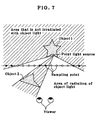
- the hidden surface removal processing is carried out in such a way that when an object is viewed from a certain visual point, a portion of the object hidden by another object placed in front thereof is invisible.
- this processing information of the object that is overlapping is added to a retinal image, applying a 3D appearance thereto.
- the hidden surface removal processing is performed by the following steps.
- Reconstructing light from the image of the object 1 reconstructed from the thus processed CGH is not diffracted at the hatched area of Fig. 7, so that when the visual point of a viewer comes in that area, the area of the object 1 corresponding to that point light source is invisible because of being hidden by the image of the object 2.
- a minute object 11 used as authenticating information of visually difficult-to-resolve size specifically, a character or the like of maximum size of 300 ⁇ m or less.
- a shielding block 12 that is larger than the minute object 11 and of visually easy-to-perceive size is located at a position where the front of the minute object 11 can be hidden in such a way that a viewer E cannot view the minute object 11 from the front (from an ordinary viewing direction), that is, at a specific position in front of the minute object 11 (on the viewing side).
- the shielding block 12 is recorded in a CGH 10.
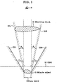
- the aforesaid hidden surface removal processing is applied to a set of point light sources representing the minute object 11, and then CGH recording is performed while holding back diffraction of at least reconstructing light from the minute object 11 between a straight line 21L and a straight line 21R shown in Fig. 1.
- the straight line 21L is defined by a straight line passing by the left end of the minute object 11 and the left end of the shielding block 12
- the straight line 21R is defined by a straight line passing by the right end of the minute object 11 and the right end of the shielding block 12. It is understood that the front direction is included between the straight line 21L and the straight line 21R.
- a straight line 22L is drawn upwardly and obliquely from the left end of the minute object 11, indicating a boundary line at a left-hand area of which there is no diffraction of reconstructing light from the left end of the minute object 11, and a straight line 22R is drawn upwardly and obliquely from the right end of the minute object 11, indicating a boundary line at a right-hand area of which there is no diffraction of reconstructing light from the right end of the minute object 11.
- the shielding block 12 used herein may be either an ordinary 2D or 3D object or an object comprising a diffraction grating pattern provided on the surface of CGH 10 and known from patent publications 1, 3, 4, etc.
- a pattern constructed of a diffraction grating that is the shielding block 12 is directly recorded in a corresponding area on the surface of CGH 10 rather than recorded as a hologram.
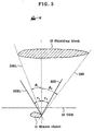
- Fig. 2 differs from that of Fig. 1 in that in order to allow a minute object 11 to be fully visible from a direction different from the front direction, for instance, from an obliquely left-hand direction, the angle of radiation, ⁇ 1 , of object light from the minute object 11 is larger than the angle ⁇ 1 of a straight line 21RL connecting the right end of the minute object 11 with the left end of the shielding block 12 with respect to the front direction.
- the angle of radiation, ⁇ 1 of object light from the minute object 11 is larger than the angle ⁇ 1 at which the tilting of the plane plate maximizes.
- a straight line 22RL is indicative of the left-hand limit to the object light.
- the aforesaid different direction is changed to an obliquely right-hand direction.
- ⁇ is the angle of radiation of the object light from the minute object 11
- a is the width from the right or left end of the minute object 11 to the left or right end of the shielding block 12
- the minute object 11 is fully visible from an obliquely left-hand or right-hand direction.
- a straight line 22R indicative of a right-hand boundary to object light emerging from the right end of a minute object 11 is located inside a straight line 21R passing by the right ends of the minute object 11 and a shielding block 12, and a straight line 22RL indicative of a left-hand boundary to object light leaving the right end of the minute object 11 is located outside a straight line 21RL passing by the right end of the minute object 11 and the left end of the shielding block 12.
- the minute object 11 is fully visible on the left side but, on the other side or the right side, it is fully hidden by the shielding block 12 and so is invisible.
- the left-hand angle of radiation, ⁇ 1 of object light from the minute object 11 is larger than the angle ⁇ 1 of a straight line 21RL connecting the right end of the minute object 11 with the left end of the shielding block 12 with respect to the front direction
- the right-hand angle of radiation, ⁇ 2 of object light from the minute object 11 is smaller than the angle ⁇ 2 of a straight line 21R connecting the right end of the minute object 11 with the right end of the shielding block 12 with respect to the front direction.
- the right-hand angle of radiation, ⁇ 2 of object light from the minute object 11 is larger than the angle ⁇ 2 of the straight line 21R connecting the right end of the minute object 11 with the right end of the shielding block 12 with respect to the front direction
- the left-hand angle of radiation, ⁇ 3 of object light leaving the minute object 11 is larger than the angle ⁇ 3 of the straight line 21L connecting the left end of the minute object 11 with the left end of the shielding block 12 with respect to the front direction.
- the range of angle wherein the minute object 11 is partly or fully visible is found to be ⁇ 2 - ⁇ 2 + ⁇ 3 - ⁇ 3 from Fig. 1.
- the range of angle wherein the minute object 1 is hidden by the shielding block 12 is found to be ⁇ 2 + ⁇ 3 . If ⁇ 2 - ⁇ 2 + ⁇ 3 - ⁇ 3 is equal to or less than ⁇ 2 + ⁇ 3 , it is then possible to make quick authentication by visual observation or using a loupe. If ⁇ 2 - ⁇ 2 + ⁇ 3 - ⁇ 3 is equal to or less than 1/2 of ⁇ 2 + ⁇ 3 , then the effect on the shielding of the minute object 11 that is authenticating information is much more enhanced; that the minute object 11 has been recorded as authenticating information is difficult to see through, ensuring even higher counterfeit-proofness.
- Fig. 4 two minute objects 11, 11' are recorded in such a way that the first minute object 11 is fully visible in the angle range ⁇ 3 - ⁇ 3 on the right side but, on the left side, it is fully hidden and so is invisible while the second minute object 11' is fully visible in the angle range ⁇ 1 - ⁇ 1 on the left side but, on the right side, it is fully hidden and so is invisible.
- This embodiment ensures much higher counterfeit-proofness because the minute objects viewed on the right and left sides of the shielding block 12 differ from each other.
- the authenticating information minute objects 11, 11'
- the authenticating information is recorded therein. Accordingly, even when the hologram is irradiated with proper illumination light, the presence of that authenticating information is greatly unlikely to be noticeable. Furthermore, even when the hologram is viewed on an enlarged scale under a loupe or the like, the presence of the authenticating information is little noticeable from an ordinary viewing direction, e.g., from the front. Thus, the concealability of the authenticating information is much more enhanced, considerably reducing the risk of forgery.
- the hologram of the present invention is observed on an enlarged scale under a loupe or the like while illuminated with proper light.
- the authenticating information minute objects 11, 11'
- the authenticating information 11, 11' develops.
- the position of viewing is moved to the front position that is in the ordinary viewing direction, the authenticating information 11, 11' is hidden by the shielding block 12 and so is not exposed to view. In this way, the hologram of the present invention is authenticated.
- the hologram of the present invention is designed such that the minute object 11 does not develop from one side (the right side of Fig. 3) that is opposite to the other side on which the minute object 11 develops from the shielding block 12 (the left side of Fig. 3) as shown in Fig. 3, the concealability of the authenticating information is then much more enhanced.
- the angle range wherein the minute object 11 is partly or wholly visible should be equal to or less than 1/2 of the angle range wherein the minute object 11 is hidden by the shielding block 12.
- the hologram of the present invention is designed such that the second minute object 11' develops on one side that is opposite to the other side on which the minute object 11 develops from the shielding block 12 as shown in Fig. 4, its counterfeit-proofness is much more enhanced.
- the boundary of diffraction light for reconstruction of the minute object 11 or the angle of radiation of object light has been described as being determined by the hidden surface removal process for CGH fabrication. Even when a hologram is fabricated by two-beam interference, however, an equivalent hologram may be fabricated by using a mask or the like to limit the range of incidence on a hologram medium of object light from the minute object to be recorded. Thus, the present invention is applicable not only to CGHs but also to holograms fabricated by a conventional two-beam interference process.
- the hologram of the present invention having authenticating information recorded therein may be applied onto the articles desired to be counterfeit-proof such as cards and documents.
- Whether or not a certain hologram has authenticating information recorded therein may be checked as described just below.
- the hologram of the present invention is designed such that the authenticating information is viewable only from a specific direction predetermined depending on a specific direction of illumination with reconstructing light.
- an authenticating information check system comprising an illumination optical system and a viewing optical system located in that direction, it is easy to test for genuineness of holograms, and cards, documents or the like onto which they are applied.
- a hologram 100 (corresponding to the CGH 10 in Figs. 1 to 4) having minute objects 11, 11' and a shielding block 12 recorded therein according to the present invention and an illuminator 101 for illuminating the hologram 100 with reconstructing illumination light are fixedly provided together with a relatively movable camera 102 for viewing the recorded authenticating information on an enlarged scale, so that the direction capable of viewing the authenticating information can be determined.
- an illuminator 101 for irradiating a hologram 100 with reconstructing illumination light and a camera 102 for viewing authenticating information recorded in the hologram 100 on an enlarged scale are fixedly provided while the hologram 100 is relatively rotatable, thereby finding the direction capable of viewing the authenticating information.
- the hologram 100 is a relief hologram such as a computer-generated hologram
- the selectivity of angle by reconstructing illumination light is not very high; even when the illuminator 102 is moved with respect to the hologram 100, the recorded minute objects 11, 11' and shielding block 12 are reconstructed while they are moved. Accordingly, the authenticating information can be viewed where the hologram 100 arrives at a given position, at which whether or not the authenticating information can be viewed can then be checked.
- a hologram 100 and a camera 102 for viewing authenticating information recorded in the hologram 100 on an enlarged scale are fixedly provided while an illuminator 101 for irradiating the hologram 100 with reconstructing illumination light is relatively movable, thereby determining which direction the authenticating direction can be viewed in.
- the illuminator 101 is moved with respect to the hologram 100, the recorded minute objects 11, 11' and shielding block 12 are reconstructed while they are moved.
- the authenticating information can be viewed; at that position, whether or not the authenticating information can actually be viewed is checked.
- a minute object that is the authenticating information is located behind a shielding block of visually easy-to-perceive size, so that the authenticating information is hidden by the shielding block in a given viewing direction and so is not exposed to view, but can be viewed from a direction different from that said direction; the presence of the authenticating information is little noticeable. Further, even when the hologram is viewed through a magnifying viewing means such as a loupe, the presence of the authenticating information is little noticeable from an ordinary viewing direction.
- the hologram of the present invention thus ensures that the concealability of the authenticating information is extremely enhanced, and so has much higher counterfeit-proofness.
Claims (19)
- Hologramme de reconstitution d'image tridimensionnelle comportant des informations d'authentification enregistrées, dans lequel :un objet minuscule, qui constitue les informations d'authentification, est situé derrière un bloc faisant écran de dimension facile à percevoir visuellement, de sorte que les informations d'authentification sont cachées par le bloc faisant écran dans une direction de visualisation donnée, et ainsi ne sont pas exposées à la vue mais peuvent être visualisées à partir d'une direction différente de ladite direction donnée.
- Hologramme selon la revendication 1, dans lequel ledit objet minuscule est de résolution difficile du point de vue visuel et peut être visualisé à travers des moyens de visualisation grossissants.
- Hologramme selon la revendication 1 ou 2, dans lequel ladite direction donnée est une direction frontale par rapport audit hologramme.
- Hologramme selon l'une quelconque des revendications 1 à 3, qui est enregistré dans une forme d'hologramme générée par ordinateur.
- Hologramme selon l'une quelconque des revendications 1 à 4, dans lequel ledit objet minuscule présente une taille maximum de 300 microns ou inférieure.
- Hologramme selon l'une quelconque des revendications 1 à 5, dans lequel ledit bloc faisant écran comprend une configuration constituée d'un réseau de diffraction enregistré dans une surface d'hologramme.
- Hologramme selon l'une quelconque des revendications 1 à 6, dans lequel ledit objet minuscule se présente sous une forme de caractère.
- Hologramme selon l'une quelconque des revendications 1 à 7, dans lequel ledit objet minuscule présente un angle de rayonnement de lumière d'objet, auquel ledit objet minuscule est entièrement visible sur un côté dudit bloc faisant écran.
- Hologramme selon l'une quelconque des revendications 1 à 8, dans lequel une distance entre ledit objet minuscule et ledit bloc formant écran est déterminée de telle sorte que ledit objet minuscule est entièrement visible sur un côté dudit bloc faisant écran, dans une direction différente de ladite direction donnée.
- Hologramme selon la revendication 8 ou 9, dans lequel ledit objet minuscule est invisible sur un côté qui est opposé à l'autre côté sur lequel ledit objet minuscule est entièrement visible.
- Hologramme selon l'une quelconque des revendications 1 à 10, dans lequel une plage angulaire dans laquelle ledit objet minuscule est partiellement ou entièrement visible est égale à ou plus étroite qu'une plage angulaire dans laquelle ledit objet minuscule est caché par ledit bloc faisant écran.
- Hologramme selon l'une quelconque des revendications 1 à 10, dans lequel une plage angulaire dans laquelle ledit objet minuscule est partiellement ou entièrement visible est égale ou plus étroite de 1/2 d'une plage angulaire dans laquelle ledit objet minuscule est caché par ledit bloc faisant écran.
- Hologramme selon l'une quelconque des revendications 8 à 10, dans lequel un autre objet minuscule est enregistré à l'intérieur, de telle sorte qu'un autre objet minuscule peut être visualisé sur un côté qui est opposé à l'autre côté sur lequel ledit objet minuscule peut être entièrement visualisé.
- Hologramme selon l'une quelconque des revendications 1 à 13, dans lequel ledit objet minuscule est reconstitué à l'intérieur d'une plage de 1 mm à partir d'une surface dudit hologramme.
- Hologramme selon l'une quelconque des revendications 1 à 14, qui est appliqué sur une carte ou un document.
- Système de vérification des informations d'authentification comprenant un système optique d'éclairage, une position de visualisation et un hologramme selon l'une quelconque des revendications 1 à 15, dans lequel le système optique d'éclairage, la position de visualisation et l'hologramme sont disposés de telle sorte que l'objet minuscule dans l'hologramme peut être visualisé par la position de visualisation.
- Système de vérification des informations d'authentification selon la revendication 16, dans lequel ledit hologramme et ledit système optique d'éclairage sont disposés de façon fixe, tandis que ladite position de visualisation est relativement mobile.
- Système de vérification des informations d'authentification selon la revendication 16, dans lequel ledit système optique d'éclairage et ladite position de visualisation sont disposés de façon fixe, tandis que ledit hologramme est relativement rotatif.
- Système de vérification des informations d'authentification selon la revendication 16, dans lequel ledit hologramme et ladite position de visualisation sont disposés de façon fixe, tandis que ledit système optique d'éclairage est relativement mobile.
Applications Claiming Priority (4)
| Application Number | Priority Date | Filing Date | Title |
|---|---|---|---|
| JP2001365628 | 2001-11-30 | ||
| JP2001365628 | 2001-11-30 | ||
| JP2002299874A JP2003228270A (ja) | 2001-11-30 | 2002-10-15 | 真贋判定情報が記録されたホログラム |
| JP2002299874 | 2002-10-15 |
Publications (2)
| Publication Number | Publication Date |
|---|---|
| EP1316915A1 EP1316915A1 (fr) | 2003-06-04 |
| EP1316915B1 true EP1316915B1 (fr) | 2005-04-20 |
Family
ID=26624778
Family Applications (1)
| Application Number | Title | Priority Date | Filing Date |
|---|---|---|---|
| EP02026883A Expired - Lifetime EP1316915B1 (fr) | 2001-11-30 | 2002-12-02 | Hologram comportant une information d'authentification enregistrée dans celui-ci |
Country Status (4)
| Country | Link |
|---|---|
| US (1) | US6844945B2 (fr) |
| EP (1) | EP1316915B1 (fr) |
| JP (1) | JP2003228270A (fr) |
| DE (1) | DE60203775T2 (fr) |
Families Citing this family (13)
| Publication number | Priority date | Publication date | Assignee | Title |
|---|---|---|---|---|
| JP4412576B2 (ja) * | 2002-10-16 | 2010-02-10 | 大日本印刷株式会社 | 立体マイクロパターン表示体 |
| JP4329999B2 (ja) * | 2004-01-07 | 2009-09-09 | 大日本印刷株式会社 | 真贋判定情報が記録されたホログラム |
| US7576898B2 (en) * | 2004-02-17 | 2009-08-18 | E. I. Du Pont De Nemours And Company | Method for using a deep image hologram as a security device and a deep image hologram |
| US8941904B2 (en) * | 2005-07-04 | 2015-01-27 | Dai Nippon Printing Co., Ltd. | Hologram sheet and hologram observation sheet using same, and blinding device |
| JP4952894B2 (ja) * | 2005-07-11 | 2012-06-13 | 大日本印刷株式会社 | ホログラムとその撮影方法 |
| CN101957586B (zh) * | 2006-06-02 | 2014-02-19 | 大日本印刷株式会社 | 全息图及其摄影方法 |
| JP4849252B2 (ja) * | 2007-02-13 | 2012-01-11 | 大日本印刷株式会社 | セキュリティ用ホログラムの作製方法 |
| DE102007013431B4 (de) * | 2007-03-15 | 2018-07-05 | Seereal Technologies S.A. | Verfahren und Einrichtung zum Rekonstruieren einer dreidimensionalen Szene mit korrigierter Sichtbarkeit |
| JP5347248B2 (ja) * | 2007-08-09 | 2013-11-20 | 大日本印刷株式会社 | 画面切替型ホログラム |
| JP5219197B2 (ja) * | 2008-05-30 | 2013-06-26 | 独立行政法人情報通信研究機構 | ホログラム生成装置およびそのプログラム |
| JP5273358B2 (ja) | 2008-07-09 | 2013-08-28 | 大日本印刷株式会社 | ホログラム作成方法、ホログラム及びそのホログラムを用いたセキュリティー媒体 |
| JP5246864B2 (ja) * | 2008-12-11 | 2013-07-24 | 独立行政法人情報通信研究機構 | ホログラム生成装置、ホログラム生成方法およびホログラム生成プログラム |
| US10394188B2 (en) | 2016-09-29 | 2019-08-27 | International Business Machines Corporation | Protection of private content and objects |
Family Cites Families (11)
| Publication number | Priority date | Publication date | Assignee | Title |
|---|---|---|---|---|
| CH588358A5 (fr) * | 1975-08-14 | 1977-05-31 | Landis & Gyr Ag | |
| DE2853953A1 (de) * | 1978-12-14 | 1980-07-03 | Hoechst Ag | Identifikationskarte |
| EP0057271B1 (fr) * | 1981-02-03 | 1984-10-10 | LGZ LANDIS & GYR ZUG AG | Procédé pour empêcher les falsifications réussies de documents et dispositif pour sa mise en oeuvre |
| CH653162A5 (de) * | 1981-10-27 | 1985-12-13 | Landis & Gyr Ag | Einrichtung zur echtheitspruefung von dokumenten. |
| JP3853871B2 (ja) | 1996-05-27 | 2006-12-06 | 大日本印刷株式会社 | 計算機ホログラムのデータ作成方法及び装置 |
| JPH1121793A (ja) | 1997-07-01 | 1999-01-26 | Toppan Printing Co Ltd | 偽造防止用紙 |
| JPH11138899A (ja) | 1997-11-11 | 1999-05-25 | Canon Inc | 画像形成装置 |
| JP2942230B2 (ja) * | 1998-01-12 | 1999-08-30 | キヤノン株式会社 | 画像形成装置及び発光装置 |
| US6351537B1 (en) * | 1998-10-05 | 2002-02-26 | 3M Innovative Properties Company | Verifiable holographic article |
| JP3708349B2 (ja) | 1999-01-25 | 2005-10-19 | 大日本印刷株式会社 | 計算機ホログラムおよびその作成方法 |
| JP3892619B2 (ja) | 1999-06-29 | 2007-03-14 | 大日本印刷株式会社 | 計算機ホログラムおよびその作成方法 |
-
2002
- 2002-10-15 JP JP2002299874A patent/JP2003228270A/ja active Pending
- 2002-12-02 US US10/307,443 patent/US6844945B2/en not_active Expired - Lifetime
- 2002-12-02 DE DE60203775T patent/DE60203775T2/de not_active Expired - Lifetime
- 2002-12-02 EP EP02026883A patent/EP1316915B1/fr not_active Expired - Lifetime
Also Published As
| Publication number | Publication date |
|---|---|
| EP1316915A1 (fr) | 2003-06-04 |
| DE60203775T2 (de) | 2006-03-09 |
| DE60203775D1 (de) | 2005-05-25 |
| US20030156305A1 (en) | 2003-08-21 |
| JP2003228270A (ja) | 2003-08-15 |
| US6844945B2 (en) | 2005-01-18 |
Similar Documents
| Publication | Publication Date | Title |
|---|---|---|
| EP1407419B1 (fr) | Dispositif optique et son procédé de fabrication | |
| CA2133559C (fr) | Methode de production d'hologrammes au moyen d'objets traites par ordinateur | |
| EP0247471A2 (fr) | Dispositifs diffractifs de sécurité présentant une grande difficulté de réplication | |
| EP1316915B1 (fr) | Hologram comportant une information d'authentification enregistrée dans celui-ci | |
| EP1612624B1 (fr) | Méthode de calcul d'un hologramme généré par ordinateur | |
| US20100014135A1 (en) | Fabrication method for a computer-generated hologram or a holographic stereogram in which a three-dimensional object having visualized cross-sectional surfaces is recorded, and computer-generated hologram/holographic stereogram in which a three-dimensional object having visualized cross-sectional surfaces is recorded | |
| US20070268536A1 (en) | Optically Variable Security Device | |
| JP5029808B2 (ja) | ホログラム作製方法及びその方法により作製されたホログラム | |
| CA2257434A1 (fr) | Procede et appareil de production d'une image holographique cachee | |
| EP1785782A2 (fr) | Hologramme de sécurité et procédés associés d'utilisation et de fabrication de celui-ci | |
| US20070188836A1 (en) | Hologram having authentication information recorded therein | |
| CA2358688C (fr) | Materiau optique a utiliser dans les documents de valeur | |
| JP4412576B2 (ja) | 立体マイクロパターン表示体 | |
| Stepien et al. | Distributed kinoforms in optical security applications | |
| EP1411399B1 (fr) | Motif holographique comportant des rubans fins | |
| Yoshikawa et al. | Floating image display with a fine pixel pitchcomputer-generated hologram | |
| JP4784782B2 (ja) | 真贋判定情報が記録されたホログラム | |
| JP3948199B2 (ja) | 計算機ホログラムおよびその作製方法 | |
| Richardson | Principles of Holography: Wavefront Reconstruction and Holographic Theory | |
| JP2008197335A (ja) | セキュリティ用ホログラムの作製方法 | |
| RU2168197C2 (ru) | Способ получения радужных голографических изображений | |
| Stępień | Computer generated holograms versus synthetic diffraction gratings in optically variable devices | |
| Son et al. | Information reduction in the 3D object Fourier hologram | |
| Odinokov et al. | Hologram authenticity test device | |
| JP2009175217A (ja) | 体積型ホログラムの作製方法及びその方法により作製された体積型ホログラム |
Legal Events
| Date | Code | Title | Description |
|---|---|---|---|
| PUAI | Public reference made under article 153(3) epc to a published international application that has entered the european phase |
Free format text: ORIGINAL CODE: 0009012 |
|
| AK | Designated contracting states |
Designated state(s): AT BE BG CH CY CZ DE DK EE ES FI FR GB GR IE IT LI LU MC NL PT SE SI SK TR |
|
| AX | Request for extension of the european patent |
Extension state: AL LT LV MK RO |
|
| 17P | Request for examination filed |
Effective date: 20031110 |
|
| AKX | Designation fees paid |
Designated state(s): DE GB |
|
| 17Q | First examination report despatched |
Effective date: 20040115 |
|
| GRAP | Despatch of communication of intention to grant a patent |
Free format text: ORIGINAL CODE: EPIDOSNIGR1 |
|
| GRAS | Grant fee paid |
Free format text: ORIGINAL CODE: EPIDOSNIGR3 |
|
| GRAA | (expected) grant |
Free format text: ORIGINAL CODE: 0009210 |
|
| AK | Designated contracting states |
Kind code of ref document: B1 Designated state(s): DE GB |
|
| REG | Reference to a national code |
Ref country code: GB Ref legal event code: FG4D |
|
| REF | Corresponds to: |
Ref document number: 60203775 Country of ref document: DE Date of ref document: 20050525 Kind code of ref document: P |
|
| PLBE | No opposition filed within time limit |
Free format text: ORIGINAL CODE: 0009261 |
|
| STAA | Information on the status of an ep patent application or granted ep patent |
Free format text: STATUS: NO OPPOSITION FILED WITHIN TIME LIMIT |
|
| 26N | No opposition filed |
Effective date: 20060123 |
|
| PGFP | Annual fee paid to national office [announced via postgrant information from national office to epo] |
Ref country code: DE Payment date: 20211210 Year of fee payment: 20 Ref country code: GB Payment date: 20211221 Year of fee payment: 20 |
|
| REG | Reference to a national code |
Ref country code: DE Ref legal event code: R071 Ref document number: 60203775 Country of ref document: DE |
|
| REG | Reference to a national code |
Ref country code: GB Ref legal event code: PE20 Expiry date: 20221201 |
|
| PG25 | Lapsed in a contracting state [announced via postgrant information from national office to epo] |
Ref country code: GB Free format text: LAPSE BECAUSE OF EXPIRATION OF PROTECTION Effective date: 20221201 |