EP1316366B1 - Vorrichtung zur Aufbewahrung und dosierten Ausgabe einer Flüssigkeit - Google Patents
Vorrichtung zur Aufbewahrung und dosierten Ausgabe einer Flüssigkeit Download PDFInfo
- Publication number
- EP1316366B1 EP1316366B1 EP02292763A EP02292763A EP1316366B1 EP 1316366 B1 EP1316366 B1 EP 1316366B1 EP 02292763 A EP02292763 A EP 02292763A EP 02292763 A EP02292763 A EP 02292763A EP 1316366 B1 EP1316366 B1 EP 1316366B1
- Authority
- EP
- European Patent Office
- Prior art keywords
- container
- product
- cavity
- metering cavity
- edge
- Prior art date
- Legal status (The legal status is an assumption and is not a legal conclusion. Google has not performed a legal analysis and makes no representation as to the accuracy of the status listed.)
- Expired - Lifetime
Links
Images



Classifications
-
- A—HUMAN NECESSITIES
- A45—HAND OR TRAVELLING ARTICLES
- A45D—HAIRDRESSING OR SHAVING EQUIPMENT; EQUIPMENT FOR COSMETICS OR COSMETIC TREATMENTS, e.g. FOR MANICURING OR PEDICURING
- A45D34/00—Containers or accessories specially adapted for handling liquid toiletry or cosmetic substances, e.g. perfumes
- A45D34/02—Scent flasks, e.g. with evaporator
-
- G—PHYSICS
- G01—MEASURING; TESTING
- G01F—MEASURING VOLUME, VOLUME FLOW, MASS FLOW OR LIQUID LEVEL; METERING BY VOLUME
- G01F11/00—Apparatus requiring external operation adapted at each repeated and identical operation to measure and separate a predetermined volume of fluid or fluent solid material from a supply or container, without regard to weight, and to deliver it
- G01F11/02—Apparatus requiring external operation adapted at each repeated and identical operation to measure and separate a predetermined volume of fluid or fluent solid material from a supply or container, without regard to weight, and to deliver it with measuring chambers which expand or contract during measurement
- G01F11/021—Apparatus requiring external operation adapted at each repeated and identical operation to measure and separate a predetermined volume of fluid or fluent solid material from a supply or container, without regard to weight, and to deliver it with measuring chambers which expand or contract during measurement of the piston type
- G01F11/025—Apparatus requiring external operation adapted at each repeated and identical operation to measure and separate a predetermined volume of fluid or fluent solid material from a supply or container, without regard to weight, and to deliver it with measuring chambers which expand or contract during measurement of the piston type with manually operated pistons
- G01F11/028—Apparatus requiring external operation adapted at each repeated and identical operation to measure and separate a predetermined volume of fluid or fluent solid material from a supply or container, without regard to weight, and to deliver it with measuring chambers which expand or contract during measurement of the piston type with manually operated pistons the dosing device being provided with a dip tube and fitted to a container, e.g. to a bottleneck
-
- G—PHYSICS
- G01—MEASURING; TESTING
- G01F—MEASURING VOLUME, VOLUME FLOW, MASS FLOW OR LIQUID LEVEL; METERING BY VOLUME
- G01F11/00—Apparatus requiring external operation adapted at each repeated and identical operation to measure and separate a predetermined volume of fluid or fluent solid material from a supply or container, without regard to weight, and to deliver it
- G01F11/10—Apparatus requiring external operation adapted at each repeated and identical operation to measure and separate a predetermined volume of fluid or fluent solid material from a supply or container, without regard to weight, and to deliver it with measuring chambers moved during operation
- G01F11/26—Apparatus requiring external operation adapted at each repeated and identical operation to measure and separate a predetermined volume of fluid or fluent solid material from a supply or container, without regard to weight, and to deliver it with measuring chambers moved during operation wherein the measuring chamber is filled and emptied by tilting or inverting the supply vessel, e.g. bottle-emptying apparatus
- G01F11/262—Apparatus requiring external operation adapted at each repeated and identical operation to measure and separate a predetermined volume of fluid or fluent solid material from a supply or container, without regard to weight, and to deliver it with measuring chambers moved during operation wherein the measuring chamber is filled and emptied by tilting or inverting the supply vessel, e.g. bottle-emptying apparatus for liquid or semi-liquid
-
- B—PERFORMING OPERATIONS; TRANSPORTING
- B05—SPRAYING OR ATOMISING IN GENERAL; APPLYING FLUENT MATERIALS TO SURFACES, IN GENERAL
- B05B—SPRAYING APPARATUS; ATOMISING APPARATUS; NOZZLES
- B05B11/00—Single-unit hand-held apparatus in which flow of contents is produced by the muscular force of the operator at the moment of use
- B05B11/01—Single-unit hand-held apparatus in which flow of contents is produced by the muscular force of the operator at the moment of use characterised by the means producing the flow
- B05B11/10—Pump arrangements for transferring the contents from the container to a pump chamber by a sucking effect and forcing the contents out through the dispensing nozzle
Definitions
- the present invention relates to a device for the packaging and metered dispensing of a product, in particular a cosmetic or a care product, such as can be used, for example, for makeup, care or hygiene of the skin or hair.
- a product in particular a cosmetic or a care product, such as can be used, for example, for makeup, care or hygiene of the skin or hair.
- Such dosage distribution can be sought, especially for products as used for example for the care or regrowth of hair.
- the device of the present invention is of the type comprising a retaining member delimiting a metering cavity, to fill in particular by total or partial reversal of the device, the product dispensing by means of the pump being in head position at the top of the device.
- the device is for example equipped with a pump ensuring the distribution of the product contained in the metering cavity, the distribution being in a position where the pump is located above the free surface of the liquid in the container containing the product to be dispensed. .
- US Pat. Nos. 3,369,713 and 5,259,536 describe bottles allowing the metered dispensing of product through the use of a retention member which fills by inverting the bottle. The dose of product is then dispensed by compressing the walls of the tube to create an overpressure inside the vial and thus push the product out of the retention member through a dispensing orifice.
- the filling of the retention member is provided by a tube arranged parallel to the axis of the bottle, a first end of which communicates with the inside of the container and a second free end opens in the retention member.
- the maximum filling level of the retention member is thus delimited by the opening defined by this second end.
- product can flow through the tube via this opening.
- a device for the packaging and metered dispensing of a liquid product comprising a longitudinal axis container X having an opening in the vicinity of which is mounted a retention element defining a metering cavity whose contents are intended to be dispensed in the head-up position of the device, the maximum filling level of the cavity being determined by an orifice in communication with both the cavity and the container, at least a part an edge defining the orifice extending inside a peripheral side wall of the metering cavity, at a non-zero distance from the latter, the maximum filling level of the metering cavity being situated substantially at the junction between the metering cavity and a portion of the retention member defining at least in part a cross sectional area greater than a cross section of the cavity at said junction.
- the free surface of the product contained in the metering cavity is formed in a plane perpendicular to the X axis which corresponds to a horizontal plane.
- the plane perpendicular to the axis X varies with respect to the plane of the free surface, the variation of a point of the plane increasing with its distance to the axis X.
- the point of the free surface of the product contained in the cavity furthest from the axis X is necessarily located at the level of at least a part of the lateral wall peripheral defining the dosing cavity.
- the entire peripheral side wall delimits the points of the free surface furthest from the axis X.
- more the orifice is remote from the peripheral side wall minus the variation of the free surface in contact with the edge delimiting the orifice is important.
- the entire edge delimiting said orifice may be located inside said lateral wall, at a distance from the latter.
- the orifice is thus further away from the side wall of the metering cavity.
- the orifice may extend at least partly outside a plane perpendicular to said axis X.
- the maximum filling level of the cavity is then determined by the lowest portion of the edge defining the orifice. According to this configuration, said lowest portion of the edge is the portion of the edge closest to the X axis.
- the orifice may be formed in an oblique plane.
- the inclination of the orifice is chosen so that when the device is inclined, the whole of the orifice remains above the free surface of the product which tilts relative to the 'orifice.
- the orifice is formed by the free end of a tube of polygonal, circular, oval or bean-shaped cross section.
- the tube may extend substantially axially from a bottom of the cavity to the free end.
- the tube being straight and extending vertically in the top position of the device, the product surplus of the cavity thus flows easily into the tube to the container.
- the portion of the retention element defining at least partly the larger cross-sectional area may extend, from the junction, to an inner wall of the container, said portion of the retention member further defining, at least in part, at least one passage allowing unidirectional flow of the product from the container to the metering cavity in response to at least partial turning of the device.
- the section (or) passage (s) is larger in the head down position of the device head up position.
- the passage (s) opens (s) under the pressure of the product during the overturning of the device and that (s) closes (s) substantially waterproof when returning to position head up.
- the retention element and in particular the portion of the retention element partially delimiting the larger cross-sectional area does not allow the return of the product passed over said portion during the reversal of the device, through the (of) passage (s), and this regardless of the gesture of reversal of the device, and in particular, the speed of execution of the reversal movement.
- the portion of the retention element partially defining the larger cross sectional area may consist of an elastically deformable membrane, a peripheral edge extends to the vicinity of the inner wall of the container.
- the membrane may comprise a portion adapted to come into contact with the inner wall of the container in head position at the top of the device, and to deviate from said inner wall of the container under the pressure of the product in response to the partial reversal.
- the portion of the membrane capable of coming into contact with the inner wall of the container may be an annular portion remote from the peripheral edge of said membrane, said portion being for example at a distance from the peripheral edge of between 0.5 and 3 mm.
- the membrane may advantageously be made, at least in part, of an elastically deformable material, in particular a material chosen from the thermoplastic or crosslinked elastomers.
- the material is chosen from silicones, natural or synthetic latices, EPDMs, polyurethanes, mixtures of polypropylene and SBS, SEBS, or EPDM, very low density polyethylenes, and mixtures based on polyesters of glycols. (TPU) or Polyether Glycol (PEBA and COPE), Soft Polyvinyl Chloride (PVC).
- the membrane may have a decreasing thickness in the direction of the inner wall of the container. This configuration makes it possible in particular to facilitate the mounting of the membrane in the container and also to facilitate the opening and closing of the passage.
- the portion partially delimiting the larger cross sectional area may be inclined towards the metering cavity. It can form with the axis X of the device an angle between 60 and 89 °. This characteristic makes it possible to promote the routing of all or part of the product situated above said portion towards the metering cavity.
- the portion of the retention element delimiting at least in part the larger cross-sectional area may be a wall extending from the junction to an edge located at least in part away from an inner wall of the container.
- the metering cavity is then filled, always by at least partial turning of the device, by a passage formed between the edge of the wall of the retention element and the inner wall of the container.
- the edge of said wall delimiting the larger cross-sectional area may extend by flexible tabs, angularly spaced, to an inner wall of the container.
- the filling of the metering cavity is then through openings defined between two consecutive legs.
- the tabs are inclined towards the metering cavity, thus facilitating the delivery of the product to said cavity.
- the retention element can be obtained by molding in one piece, which makes it possible in particular to manufacture it at low cost and to facilitate its mounting in the container.
- the retention element may comprise hooking means mounted on an edge of the container defining the opening of the container.
- the device may further comprise a pump provided for dispensing the product.
- the pump is secured to a dip tube whose end is located substantially in the vicinity of a bottom of the dosing cavity. The presence of the dip tube allows the realization of a metering cavity of greater volume.
- the pump is preferably integral with a hoop, fixedly mounted on a neck of the container, in particular by snapping or screwing. It can be surmounted by an organ, in particular in the form of a push button, for actuating said pump.
- the device according to the invention is particularly suitable for the packaging and dispensing of a cosmetic or care product, especially for the skin or hair, for example a nutritious root care or a scalp care.
- the device shown in FIG. 1 comprises an X-axis container 10 designed to receive product P and having a substantially cylindrical body 11 of circular cross-section, one end of which is closed by a bottom 12. An end opposite the bottom presents a neck 13 whose free edge 14 defines an opening 15 in the vicinity of which is mounted, in the axis X of the container, a retention member 20.
- the outer surface of the neck 13 comprises a thread 130, adapted to cooperate with a thread 600 on the inner surface of a mounting ring 60.
- the retention element delimits a metering cavity 21 whose contents are intended to be distributed in head position at the top of the device, by any means known to those skilled in the art. allowing a head-up distribution.
- a pump 50 is provided for dispensing the product.
- the pump 50 is fed from the retention element 20 which will be described in detail later.
- the pump is fixed to the container 10, via the mounting band 60.
- An actuating member in the form of a push button 70 allows the actuation of the pump and the product outlet through at least one outlet port 80.
- the constituent elements of the device in particular the container 10, the retention element 20, the pump 50, the hoop 60, and the push button 70 may be obtained by molding a thermoplastic material, in particular a polypropylene or a polyethylene.
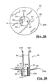
- the retention element 20 shown in isolation in Figures 2A and 2B and placed inside the device in Figure 1, comprises a continuous peripheral side wall 210 closed at one end by a bottom 213.
- the side wall 210 is a cylinder of circular cross section and the bottom is a plane disk.
- the side wall may have any other shape, as well as the bottom which may for example be concave or have a U-shaped profile.
- the side wall 210 is extended axially by hooking tabs 24, for example three regularly spaced legs, which each end with a rim 240 bearing on the free edge 14 of the neck of the container 10.
- the side wall 210 terminates in a second end 212 from which extends substantially transversely a membrane 22, to an inner wall 110 of the container.
- the membrane separates a first zone A from the container in which the product P remains when the device is in the upwardly facing position, of a second zone B adjacent to the opening 15 of the container.
- the membrane 22 When the device is in the head-up position, the membrane 22 defines with a portion of the inner wall 110 of the container a zone 23 of greater cross section than the cross section of the metering cavity at the edge 212.
- the membrane 22 is in further able to define in combination with the inner wall 110 of the container an annular passage 40, shown only in Figure 3A.
- the membrane 22 is configured to allow unidirectional flow of the product to the metering cavity in response to at least partial reversal of the device through the annular passage 40.
- the membrane 22 is an elastically deformable membrane.
- a peripheral edge 220 of the membrane extends to the vicinity of the inner wall 110 of the container as seen in Figure 1.
- the membrane comprises an annular portion 221 which is adapted to come into contact, preferably substantially sealed, with a shoulder, described later, provided in the inner wall 110 of the container head position at the top of the device.
- substantially sealed reflects the fact that most of the product passed over the membrane can not flow into the container when returning to the head-up position. Under the pressure of the product in response to the partial reversal of the device, the membrane deviates from the wall so as to delimit, with the inner wall 110, the passage 40.
- the membrane is made of an elastically deformable material chosen from, for example, thermoplastic or crosslinked elastomers.
- an elastically deformable material chosen from, for example, thermoplastic or crosslinked elastomers.
- silicones natural or synthetic latices, EPDMs, polyurethanes, mixtures of polypropylene and of SBS, SEBS, or EPDM, very low density polyethylenes, blends based on polyesters glycols (TPU) or polyether glycols (PEBA and COPE), polyvinyl chloride soft (PVC).
- TPU polyesters glycols
- PEBA and COPE polyether glycols
- PVC polyvinyl chloride soft
- such a material has a hardness of between 20 Shore A and 40 Shore D, preferably between 40 Shore A and 75 Shore A. Its elasticity can range from 0.5 to 5 MPa, and preferably from 8 to 2 MPa (tensile stress at 100% elongation).
- a silicone elastomer is chosen.
- the membrane 22 is inclined towards the metering cavity 21. It forms with the longitudinal axis X of the device, an angle ⁇ example equal to about 85 °. This inclination contributes to convey the product to the metering cavity.
- the inner wall 110 of the container forms a shoulder 111 for receiving the portion 221 of the membrane when the device is in the upward position.
- the upper inner surface 112 of the shoulder has an angle ⁇ with the longitudinal axis of the container, for example equal to about 60 ° so as to receive the portion 221 of the membrane and keep it inclined.
- the membrane has a decreasing thickness in the direction of the inner wall of the container.
- the membrane is provided with at least one valve which is able to open under the pressure of the product in response to the partial reversal of the device and to close during the return of the device in head up position.
- the overflow system of the metering cavity is a tube 32, open at both ends, of cross section in the form of beans.
- the tube 32 extends from the bottom 213 of the cavity along an axis parallel to the axis X, to a free end 31 which defines an orifice 30. Due to the presence of the pump 50 in the axis X, the overflow tube 32 is located substantially at a distance from the X axis. But it is obvious that with a different arrangement of the product distribution system, the overflow tube 32 could be formed in the X.
- the orifice 30 is advantageously formed in a plane oblique, inclined relative to the plane perpendicular to the axis X, the lowest portion 310 of the edge 31 which defines the orifice 30 then determining the maximum filling height of the metering cavity.
- the volume of the metering cavity is of the order of a few milliliters.
- the lower portion 310 of the edge 31 delimiting the maximum filling level of the metering cavity is the portion of the edge closest to the X axis, namely the edge portion furthest from the peripheral side wall 210.
- the lowest portion 310 of the edge 31 which delimits the maximum filling height of the metering cavity is advantageously at an axial height substantially corresponding to the axial height of the second end 212 of the side wall 210 from which extends the membrane 22.
- the zone 23 of larger cross section is formed at the axial height corresponding to the maximum filling level of the metering cavity.
- An air passage tube 27 is advantageously provided in the metering cavity to accelerate the filling of the metering cavity and its emptying by promoting the passage of air between the two zones defined by the membrane.
- the air passage tube 27 is formed inside the cavity along an axis parallel to the axis X, and opens out above the free end 31 delimiting the overflow orifice so that it does not affect the maximum filling level of the dosing cavity.
- the mounting of the device is as follows.
- the retention element 20 is obtained by molding and formed in one piece.
- the membrane is molded at a 90 ° angle with the side wall 210 of the metering cavity. It is obvious that it can be molded at a lower angle so as to obtain the inclination towards the metering cavity.
- the retention element 20 After filling the container with the product P, the retention element 20 has entered the container 10 through the neck 13 until the edge 240 bears against the neck 13 of the container 10.
- the inclination of the membrane towards the metering cavity is obtained in that the portion 221 of the membrane is applied to the upper inner surface 112 of the shoulder 111 inclined by 60 °.
- the pump 50 is then positioned inside the container 10.
- FIGS. 3A-3C illustrate various steps of filling the metering cavity of the device which has just been described with reference to FIG.
- the device is turned upside down so that the weight of the product P and the flexibility of the membrane allows the latter to bend towards the opening of the container.
- the passage 40 is thus defined between said peripheral edge 220 and the inner wall 110 of the container.
- the product P flows through the passage 40 as shown by the arrow F1. If the residual amount of product is sufficient, a portion of the product P can also flow through the tube 32 inside the metering cavity 21. Part of the zone B is then filled with product P. This zone B is dimensioned so that its volume is significantly larger than that of the metering cavity.
- the membrane When turning the device from the head-down position of FIG. 3A to the head-up position of FIG. 3B, the membrane returns to its initial position under the combined effect of the weight of the product and the elasticity of the material forming it. . The membrane then applies to the shoulder 111 so that the passage 40 closes. The product P present above the membrane then flows inside the metering cavity 21. Any excess product in the metering cavity 21 falls into the zone A of the container 10 by overflow via the orifice 30, as this is indicated by the arrow F2. The maximum volume of the metering cavity is obtained when the free surface of the product in the metering cavity 21 reaches the lowest portion 310 of the free end 31 of the tube as illustrated in Figure 3C. The metering cavity is thus filled always substantially in the same way, and this, whatever the conditions of turning the container from the head down position to the head up position.
- the product contained in the metering cavity 21 flows into the part of the zone 23 located on the side of the tube 32. thus lowering the level of the free surface of the product in contact with the lowest portion 310 of the free end 31 of the tube.
- the product can not then reach the orifice 30.
- all the product initially retained in the metering cavity will be distributed because as the product is distributed, In the metering cavity, the product in zone 23 flows back into the metering cavity as it empties.
- FIGS. 5A to 5C illustrate a second embodiment of the device of the invention which differs from that which has just been described in particular in that the retention element 20, illustrated alone in FIG. does not include a membrane.
- the peripheral side wall 210 of the metering cavity terminates, opposite the bottom 213, by a second end 212 from which this time extends a substantially rigid wall 25.
- the wall 25 is a continuous wall which comprises a first annular portion formed substantially transversely to the X axis, at the end of which is formed a second portion, along the X axis, which ends with an edge 250.
- the edge 250 is located at a distance from the inner wall 110 of the container.
- the wall 25 delimits an area 26 of greater cross section than the cross section of the metering cavity at the junction 212.
- flexible tabs 28 are formed substantially transversely to the X axis and extend radially to the inner wall 110 of the container.
- the flexible tabs are advantageously inclined towards the metering cavity 21 and provided with flanges 280 on their radial edges. Passes 41 are delimited between two consecutive flexible tabs.
- the wall 25 and the flexible tabs 28 separate a first zone A of the container in which the product P remains when the device is in the upwardly facing position, of a second zone B adjacent to the opening 15 of the container.
- the device is turned upside down so that the product staying in the zone A of the container flows into the zone B through the passages 41.
- the product in zone B is conveyed to the metering cavity 21, in particular thanks to the flexible tabs 28 inclined towards said cavity, the flanges 280 further improving the guiding of the product to the cavity.
- the product then flows through the overflow orifice 30 until the free surface of the product reaches the lowest portion 310 of the free end of the tube 32, as shown in FIG. 5A, so that only the metering cavity 21 is filled.
Landscapes
- Physics & Mathematics (AREA)
- Fluid Mechanics (AREA)
- General Physics & Mathematics (AREA)
- Containers And Packaging Bodies Having A Special Means To Remove Contents (AREA)
- Supply Of Fluid Materials To The Packaging Location (AREA)
- Basic Packing Technique (AREA)
- Sampling And Sample Adjustment (AREA)
- Containers And Plastic Fillers For Packaging (AREA)
- Control And Other Processes For Unpacking Of Materials (AREA)
Claims (24)
- Vorrichtung zur Verpackung und zur dosierten Ausgabe eines flüssigen Produkts, mit einem Behälter (10) mit einer Längsachse X, der eine Öffnung (15) aufweist, in deren Nähe ein Aufnahmeelement (20) montiert ist, das einen Dosierhohlraum (21) begrenzt, dessen Inhalt in der aufrechten Stellung der Vorrichtung ausgegeben werden soll, wobei der maximale Füllpegel des Hohlraums (21) durch eine Öffnung (30) bestimmt wird, die sowohl mit dem Hohlraum (21) aus auch mit dem Behälter (10) in Verbindung steht, wobei mindestens ein Teil eines die Öffnung begrenzenden Rands (31) sich innerhalb einer Umfangsseitenwand (210) des Dosierhohlraums in einem Abstand ungleich Null zu dieser letzteren erstreckt, dadurch gekennzeichnet, dass der maximale Füllpegel des Hohlraums (21) sich im Wesentlichen an der Verbindungsstelle (212) zwischen dem Dosierhohlraum (21) und einem Abschnitt (22; 25) des Aufnahmeelements befindet, der zumindest zum Teil eine Zone (23; 26) mit einem Querschnitt begrenzt, der größer ist als ein Querschnitt des Hohlraums (21) in Höhe der Verbindungsstelle (212).
- Vorrichtung nach Anspruch 1, dadurch gekennzeichnet, dass die Gesamtheit des Rands (31), der die Öffnung (30) begrenzt, sich innerhalb der Umfangsseitenwand (210) in Abstand zu dieser befindet.
- Vorrichtung nach einem der vorhergehenden Ansprüche, dadurch gekennzeichnet, dass die Öffnung (30) sich mindestens teilweise außerhalb einer Ebene lotrecht zur Achse X befindet.
- Vorrichtung nach Anspruch 3, dadurch gekennzeichnet, dass die Öffnung (30) in einer schrägen Ebene ausgebildet ist.
- Vorrichtung nach Anspruch 2 oder 3, dadurch gekennzeichnet, dass der maximale Füllpegel des Dosierhohlraums (21) von dem Abschnitt (310) des Rands (31) definiert wird, der der Achse X am nächsten liegt.
- Vorrichtung nach einem der vorhergehenden Ansprüche, dadurch gekennzeichnet, dass die Öffnung (30) vom freien Ende (31) eines Rohrs (32) mit einem polygonalen, kreisförmigen, ovalen oder bohnenförmigen Querschnitt gebildet wird.
- Vorrichtung nach Anspruch 6, dadurch gekennzeichnet, dass das Rohr (32) sich im Wesentlichen axial von einem Boden (213) des Hohlraums bis zum freien Ende (31) erstreckt.
- Vorrichtung nach einem der vorhergehenden Ansprüche, dadurch gekennzeichnet, dass der Abschnitt (22) des Aufnahmeelements, der zumindest zum Teil die Zone (23) begrenzt, sich ausgehend von der Verbindungsstelle (212) bis zu einer Innenwand (110) des Behälters erstreckt, wobei der Abschnitt (22) des Aufnahmeelements außerdem zumindest zum Teil mindestens einen Durchlass (40) begrenzt, der ein Einweg-Fließen des vom Behälter kommenden Produkts zum Dosierhohlraum (21) als Reaktion auf ein zumindest teilweises Umdrehen der Vorrichtung ermöglicht.
- Vorrichtung nach Anspruch 8, dadurch gekennzeichnet, dass der Abschnitt (22) des Aufnahmeelements aus einer elastisch verformbaren Membran besteht, von der ein Umfangsrand (220) sich bis in die Nähe der Innenwand (110) des Behälters erstreckt, wobei die Membran einen Abschnitt (221) aufweist, der in der aufrechten Stellung der Vorrichtung in Kontakt mit der Innenwand (110) des Behälters kommen und sich unter dem Druck des Produkts als Reaktion auf das teilweise Umdrehen von der Wand entfernen kann.
- Vorrichtung nach Anspruch 9, dadurch gekennzeichnet, dass der Abschnitt (221) der Membran, der mit der Innenwand des Behälters (110) in Kontakt kommen kann, ein ringförmiger Abschnitt ist, der vom Umfangsrand (220) der Membran entfernt ist.
- Vorrichtung nach einem der Ansprüche 9 oder 10, dadurch gekennzeichnet, dass die Membran aus einem elastisch verformbaren Material besteht, insbesondere aus einem Material, das unter den thermoplastischen oder vernetzten Elastomermaterialien ausgewählt wird.
- Vorrichtung nach Anspruch 11, dadurch gekennzeichnet, dass das Material unter den Silikonen, dem natürlichen oder synthetischen Latex, den EPDM, den Polyurethanen, den Mischungen von Polypropylen und SBS, SEBS oder EPDM, den Polyethylenen sehr niederer Dichte, den Mischungen auf der Basis von Polyesterglykolen (TPU) oder Polyetherglykolen (PESA und COPE), den weichen Polyvinylchloriden (PVC) ausgewählt wird.
- Vorrichtung nach einem der Ansprüche 9 bis 12, dadurch gekennzeichnet, dass die Membran eine in Richtung der Innenwand (110) des Behälters abnehmende Stärke aufweist.
- Vorrichtung nach einem der Ansprüche 8 bis 13, dadurch gekennzeichnet, dass der Abschnitt (22) des Aufnahmeelements in Richtung des Dosierhohlraums (21) geneigt ist.
- Vorrichtung nach Anspruch 14, dadurch gekennzeichnet, dass der Abschnitt (22) des Aufnahmeelements mit der Achse X einen Winkel zwischen 60 und 89° bildet.
- Vorrichtung nach einem der Ansprüche 1 bis 7, dadurch gekennzeichnet, dass der Abschnitt (25) des Aufnahmeelements, der die Zone (26) zumindest zum Teil begrenzt, eine Wand ist, die sich ausgehend von der Verbindungsstelle (212) bis zu einem Rand (250) erstreckt, der zumindest zum Teil in Abstand von einer Innenwand des Behälters angeordnet ist.
- Vorrichtung nach Anspruch 16, dadurch gekennzeichnet, dass die Wand (25) sich radial ausgehend vom Rand (250) durch winkelmäßig voneinander entfernte biegsame Laschen (28) bis zur Innenwand (110) des Behälters verlängert.
- Vorrichtung nach Anspruch 17, dadurch gekennzeichnet, dass die biegsamen Laschen (28) zum Dosierhohlraum (21) geneigt sind.
- Vorrichtung nach einem der vorhergehenden Ansprüche, dadurch gekennzeichnet, dass das Aufnahmeelement (20) durch Formen aus einem Stück erhalten wird.
- Vorrichtung nach einem der vorhergehenden Ansprüche, dadurch gekennzeichnet, dass das Aufnahmeelement (20) Befestigungsmittel (24) aufweist, die auf einen Rand (14) des Behälters (10) montiert sind, der die Öffnung (15) begrenzt.
- Vorrichtung nach einem der vorhergehenden Ansprüche, dadurch gekennzeichnet, dass sie außerdem eine Pumpe (50) aufweist, die vorgesehen ist, um das Produkt (P) auszugeben, wobei die Pumpe fest mit einem Tauchrohr (51) verbunden ist, von dem ein Ende sich im Wesentlichen in der Nähe eines Bodens (213) des Dosierhohlraums (21) befindet.
- Vorrichtung nach Anspruch 21, dadurch gekennzeichnet, dass die Pumpe (50) fest mit einem Mantelring (60) verbunden ist, der ortsfest auf einen Hals (13) des Behälters montiert ist, insbesondere durch Einrasten oder Schraubverbindung.
- Vorrichtung nach einem der Ansprüche 21 bis 22, dadurch gekennzeichnet, dass über der Pumpe (50) ein Organ, insbesondere in Form eines Druckknopfs (70) sitzt, um die Pumpe zu betätigen.
- Verwendung einer Vorrichtung nach einem der vorhergehenden Ansprüche zur Verpackung und zur Ausgabe eines Kosmetik- oder Pflegeprodukts (P), insbesondere für die Haut oder die Haare.
Applications Claiming Priority (2)
| Application Number | Priority Date | Filing Date | Title |
|---|---|---|---|
| FR0115182A FR2832699B1 (fr) | 2001-11-23 | 2001-11-23 | Dispositif pour le conditionnement et la distribution dosee d'un produit liquide |
| FR0115182 | 2001-11-23 |
Publications (3)
| Publication Number | Publication Date |
|---|---|
| EP1316366A2 EP1316366A2 (de) | 2003-06-04 |
| EP1316366A3 EP1316366A3 (de) | 2005-09-21 |
| EP1316366B1 true EP1316366B1 (de) | 2007-01-03 |
Family
ID=8869721
Family Applications (1)
| Application Number | Title | Priority Date | Filing Date |
|---|---|---|---|
| EP02292763A Expired - Lifetime EP1316366B1 (de) | 2001-11-23 | 2002-11-06 | Vorrichtung zur Aufbewahrung und dosierten Ausgabe einer Flüssigkeit |
Country Status (8)
| Country | Link |
|---|---|
| US (1) | US7114640B2 (de) |
| EP (1) | EP1316366B1 (de) |
| JP (1) | JP2003237864A (de) |
| AT (1) | ATE350169T1 (de) |
| CA (1) | CA2411718C (de) |
| DE (1) | DE60217276T2 (de) |
| ES (1) | ES2277994T3 (de) |
| FR (1) | FR2832699B1 (de) |
Families Citing this family (10)
| Publication number | Priority date | Publication date | Assignee | Title |
|---|---|---|---|---|
| FR2892608B1 (fr) | 2005-11-03 | 2008-05-30 | Techpack Int Sa | Distributeur applicateur d'un produit pateux |
| DE102007012804A1 (de) * | 2007-03-16 | 2008-09-25 | Pari Pharma Gmbh | Aerosolgenerator |
| USD636668S1 (en) * | 2008-03-24 | 2011-04-26 | Mary Kay Inc. | Dip tubes |
| US9079201B2 (en) * | 2010-01-22 | 2015-07-14 | Finishing Brands Holdings Inc. | Liquid supply system for a gravity feed spray device |
| US20120018458A1 (en) | 2010-07-26 | 2012-01-26 | Ecolab Usa Inc. | Metered dosing bottle |
| USD732972S1 (en) | 2013-08-22 | 2015-06-30 | Natura Cosmeticos S.A. | Flask |
| AU2015311731A1 (en) * | 2014-09-05 | 2017-03-23 | Big Monster Toys Llc | Spill-preventing snack container and dispenser |
| GB201720561D0 (en) * | 2017-12-10 | 2018-01-24 | Simard Jo-Anne | Fluid measuring and dispensing device |
| KR102100784B1 (ko) * | 2017-12-21 | 2020-04-14 | 이도훈 | 폴리케톤 재질의 부품을 갖는 펌프가 장착된 화장품 용기 |
| CZ2019344A3 (cs) * | 2019-06-04 | 2020-02-19 | Dušan Pomianovský | Aplikátor kapalin |
Family Cites Families (24)
| Publication number | Priority date | Publication date | Assignee | Title |
|---|---|---|---|---|
| US1896405A (en) | 1932-05-16 | 1933-02-07 | Bonner B Hauser | Ink bottle |
| US3029001A (en) | 1959-12-28 | 1962-04-10 | Matthew B Blish | Flexible dispensing closure for rigid containers |
| US3347420A (en) * | 1965-08-16 | 1967-10-17 | Robert J Donoghue | Multi-compartment container for dispensing measured quantities of a plurality of liquids |
| US3369713A (en) * | 1966-04-08 | 1968-02-20 | Smith Kline French Lab | Device for dispensing measured quantities of liquid |
| US3379136A (en) | 1966-08-26 | 1968-04-23 | Diamond Int Corp | Liquid dispenser |
| US3402860A (en) * | 1966-12-20 | 1968-09-24 | Mckesson & Robbins Inc | Combination closure and liquid metering dispenser for squeeze bottles |
| JPS5328854B2 (de) | 1973-06-19 | 1978-08-17 | ||
| JPS5316534Y2 (de) * | 1973-06-09 | 1978-05-01 | ||
| US4159791A (en) | 1977-04-04 | 1979-07-03 | Crutcher William C | Measuring and dispensing device |
| FR2393279A1 (fr) | 1977-06-03 | 1978-12-29 | Normos Norbert | Dispositif de prelevement de doses precises et constantes de liquide |
| US4324349A (en) | 1980-01-14 | 1982-04-13 | Kaufman John George | Container for dispensing liquid |
| DE3517558A1 (de) | 1985-05-15 | 1986-11-20 | Ing. Erich Pfeiffer GmbH & Co KG, 7760 Radolfzell | Handbetaetigte ausgabeeinrichtung fuer medien |
| JPS6354654U (de) * | 1985-12-23 | 1988-04-12 | ||
| US5259536A (en) * | 1986-02-07 | 1993-11-09 | Reyman Mark E | Device for the controlled measuring and dispensing of a fluid |
| JPS6354654A (ja) | 1986-08-26 | 1988-03-09 | Nec Corp | Romカ−ド |
| JPH02135465A (ja) | 1988-11-17 | 1990-05-24 | Konica Corp | 複写機 |
| JPH074215Y2 (ja) * | 1989-04-14 | 1995-02-01 | 株式会社資生堂 | 定量注出栓 |
| FR2705590B1 (fr) * | 1993-05-26 | 1995-07-28 | Step | Dispositif de distribution de liquide utilisable en position droite et ne comportant pas de tube-plongeur. |
| US5346105A (en) * | 1993-12-30 | 1994-09-13 | Dart Industries Inc. | Dispenser for granular material |
| US6179170B1 (en) | 1999-04-27 | 2001-01-30 | George M. Bachand | Dispenser assembly and insert tank for same |
| FR2799449B1 (fr) * | 1999-10-06 | 2001-12-14 | Oreal | Flacon doseur a pompe |
| WO2001042117A1 (en) * | 1999-12-13 | 2001-06-14 | Irwin Aram J | Combined fluid and pop-up sheet product dispensing system |
| FR2811644B1 (fr) * | 2000-07-12 | 2002-09-06 | Oreal | Dispositif pour le conditionnement et la distribution dosee d'un produit liquide |
| FR2817244B1 (fr) | 2000-11-24 | 2003-01-10 | Oreal | Dispositif ameliore pour le conditionnement et la distribution dosee d'un produit liquide |
-
2001
- 2001-11-23 FR FR0115182A patent/FR2832699B1/fr not_active Expired - Fee Related
-
2002
- 2002-11-06 DE DE60217276T patent/DE60217276T2/de not_active Expired - Lifetime
- 2002-11-06 AT AT02292763T patent/ATE350169T1/de not_active IP Right Cessation
- 2002-11-06 EP EP02292763A patent/EP1316366B1/de not_active Expired - Lifetime
- 2002-11-06 ES ES02292763T patent/ES2277994T3/es not_active Expired - Lifetime
- 2002-11-15 CA CA002411718A patent/CA2411718C/fr not_active Expired - Fee Related
- 2002-11-25 JP JP2002341435A patent/JP2003237864A/ja not_active Withdrawn
- 2002-11-25 US US10/302,819 patent/US7114640B2/en not_active Expired - Fee Related
Also Published As
| Publication number | Publication date |
|---|---|
| DE60217276D1 (de) | 2007-02-15 |
| CA2411718A1 (fr) | 2003-05-23 |
| FR2832699B1 (fr) | 2004-01-30 |
| CA2411718C (fr) | 2006-10-17 |
| EP1316366A2 (de) | 2003-06-04 |
| DE60217276T2 (de) | 2007-06-28 |
| ES2277994T3 (es) | 2007-08-01 |
| US20030116589A1 (en) | 2003-06-26 |
| EP1316366A3 (de) | 2005-09-21 |
| ATE350169T1 (de) | 2007-01-15 |
| JP2003237864A (ja) | 2003-08-27 |
| FR2832699A1 (fr) | 2003-05-30 |
| US7114640B2 (en) | 2006-10-03 |
Similar Documents
| Publication | Publication Date | Title |
|---|---|---|
| CA2349781C (fr) | Embout doseur pour la distribution d'une dose a volume variable et ensemble equipe d'un tel embout doseur | |
| EP0952090B1 (de) | Dosieraufsatz | |
| EP1156300B1 (de) | Dosieransatz und Behälter mit einem solchen Ansatz | |
| EP1208916B1 (de) | Verbesserte Vorrichtung zur Verpackung und der dosierten Abgabe von Flüssigkeit | |
| EP1044893B1 (de) | Vorrichtung zum unmittelbaren Vermischen von mindestens zwei Produkten, von denen eines ein Pulver ist | |
| EP0649795B1 (de) | Ausgabevorrichtung, versehen mit einem Rückschlagventil | |
| CA2286377C (fr) | Embout doseur et recipient equipe d'un embout doseur selon l'invention | |
| EP0945368A1 (de) | Auftragskopf zur Abgabe von einem Produkt, insbesondere Haarpflegeprodukt, und Verpackungseinheit mit einem solchen Kopf | |
| EP0335763A1 (de) | Vorrichtung zur Abgabe einer Mischung aus einer pastenartigen Substanz und mindestens einer zusätzlichen Substanz, insbesondere in Form eines gestreiften Stranges, und Abgabekopf einer solcher Vorrichtung | |
| EP1172151A1 (de) | Vorrichtung zur Verpackung und der dosierten Abgabe von Flüssigkeit | |
| EP1138393B1 (de) | Belüftungsvorrichtung, Verschlusskapsel mit einer solchen Vorrichtung, Behälter mit einer solchen Vorrichtung oder einer solchen Verschlusskapsel, und Einheit mit einem solchen Behälter | |
| EP0786419A1 (de) | Flasche mit Dosiervorrichtung | |
| CA2411718C (fr) | Dispositif pour le conditionnement et la distribution dosee d'un produit liquide | |
| WO2021009324A1 (fr) | Distributeur de fluide | |
| EP0855350A1 (de) | Druckgasbehälter mit zwei Ventilen | |
| FR3118953A1 (fr) | «Distributeur de fluide de fluide compact» | |
| EP1095706B1 (de) | Flasche mit Dosiervorrichtung und Pumpe | |
| FR2892608A1 (fr) | Distributeur applicateur d'un produit pateux | |
| EP1442998B1 (de) | Elastische Verschlussvorrichtung und Behälter | |
| FR3118954A1 (fr) | «Distributeur de fluide muni d’un bouton de dosage» | |
| FR2876257A1 (fr) | Distributeur d'un produit fluide, typiquement d'un produit cosmetique fluide | |
| FR3040274A1 (fr) | Dispositif de conditionnement et prelevement d'un produit. |
Legal Events
| Date | Code | Title | Description |
|---|---|---|---|
| PUAI | Public reference made under article 153(3) epc to a published international application that has entered the european phase |
Free format text: ORIGINAL CODE: 0009012 |
|
| AK | Designated contracting states |
Designated state(s): AT BE BG CH CY CZ DE DK EE ES FI FR GB GR IE IT LI LU MC NL PT SE SK TR |
|
| AX | Request for extension of the european patent |
Extension state: AL LT LV MK RO SI |
|
| PUAL | Search report despatched |
Free format text: ORIGINAL CODE: 0009013 |
|
| AK | Designated contracting states |
Kind code of ref document: A3 Designated state(s): AT BE BG CH CY CZ DE DK EE ES FI FR GB GR IE IT LI LU MC NL PT SE SK TR |
|
| AX | Request for extension of the european patent |
Extension state: AL LT LV MK RO SI |
|
| 17P | Request for examination filed |
Effective date: 20060321 |
|
| AKX | Designation fees paid |
Designated state(s): AT BE BG CH CY CZ DE DK EE ES FI FR GB GR IE IT LI LU MC NL PT SE SK TR |
|
| GRAP | Despatch of communication of intention to grant a patent |
Free format text: ORIGINAL CODE: EPIDOSNIGR1 |
|
| GRAS | Grant fee paid |
Free format text: ORIGINAL CODE: EPIDOSNIGR3 |
|
| GRAA | (expected) grant |
Free format text: ORIGINAL CODE: 0009210 |
|
| AK | Designated contracting states |
Kind code of ref document: B1 Designated state(s): AT BE BG CH CY CZ DE DK EE ES FI FR GB GR IE IT LI LU MC NL PT SE SK TR |
|
| PG25 | Lapsed in a contracting state [announced via postgrant information from national office to epo] |
Ref country code: IE Free format text: LAPSE BECAUSE OF FAILURE TO SUBMIT A TRANSLATION OF THE DESCRIPTION OR TO PAY THE FEE WITHIN THE PRESCRIBED TIME-LIMIT Effective date: 20070103 Ref country code: FI Free format text: LAPSE BECAUSE OF FAILURE TO SUBMIT A TRANSLATION OF THE DESCRIPTION OR TO PAY THE FEE WITHIN THE PRESCRIBED TIME-LIMIT Effective date: 20070103 Ref country code: DK Free format text: LAPSE BECAUSE OF FAILURE TO SUBMIT A TRANSLATION OF THE DESCRIPTION OR TO PAY THE FEE WITHIN THE PRESCRIBED TIME-LIMIT Effective date: 20070103 Ref country code: NL Free format text: LAPSE BECAUSE OF FAILURE TO SUBMIT A TRANSLATION OF THE DESCRIPTION OR TO PAY THE FEE WITHIN THE PRESCRIBED TIME-LIMIT Effective date: 20070103 Ref country code: AT Free format text: LAPSE BECAUSE OF FAILURE TO SUBMIT A TRANSLATION OF THE DESCRIPTION OR TO PAY THE FEE WITHIN THE PRESCRIBED TIME-LIMIT Effective date: 20070103 |
|
| REG | Reference to a national code |
Ref country code: GB Ref legal event code: FG4D Free format text: NOT ENGLISH |
|
| REF | Corresponds to: |
Ref document number: 60217276 Country of ref document: DE Date of ref document: 20070215 Kind code of ref document: P |
|
| REG | Reference to a national code |
Ref country code: IE Ref legal event code: FG4D Free format text: LANGUAGE OF EP DOCUMENT: FRENCH |
|
| PG25 | Lapsed in a contracting state [announced via postgrant information from national office to epo] |
Ref country code: SE Free format text: LAPSE BECAUSE OF FAILURE TO SUBMIT A TRANSLATION OF THE DESCRIPTION OR TO PAY THE FEE WITHIN THE PRESCRIBED TIME-LIMIT Effective date: 20070403 |
|
| PG25 | Lapsed in a contracting state [announced via postgrant information from national office to epo] |
Ref country code: BG Free format text: LAPSE BECAUSE OF THE APPLICANT RENOUNCES Effective date: 20070404 |
|
| GBT | Gb: translation of ep patent filed (gb section 77(6)(a)/1977) |
Effective date: 20070329 |
|
| PG25 | Lapsed in a contracting state [announced via postgrant information from national office to epo] |
Ref country code: PT Free format text: LAPSE BECAUSE OF FAILURE TO SUBMIT A TRANSLATION OF THE DESCRIPTION OR TO PAY THE FEE WITHIN THE PRESCRIBED TIME-LIMIT Effective date: 20070604 |
|
| NLV1 | Nl: lapsed or annulled due to failure to fulfill the requirements of art. 29p and 29m of the patents act | ||
| REG | Reference to a national code |
Ref country code: ES Ref legal event code: FG2A Ref document number: 2277994 Country of ref document: ES Kind code of ref document: T3 |
|
| REG | Reference to a national code |
Ref country code: IE Ref legal event code: FD4D |
|
| PLBE | No opposition filed within time limit |
Free format text: ORIGINAL CODE: 0009261 |
|
| STAA | Information on the status of an ep patent application or granted ep patent |
Free format text: STATUS: NO OPPOSITION FILED WITHIN TIME LIMIT |
|
| PG25 | Lapsed in a contracting state [announced via postgrant information from national office to epo] |
Ref country code: SK Free format text: LAPSE BECAUSE OF FAILURE TO SUBMIT A TRANSLATION OF THE DESCRIPTION OR TO PAY THE FEE WITHIN THE PRESCRIBED TIME-LIMIT Effective date: 20070103 |
|
| 26N | No opposition filed |
Effective date: 20071005 |
|
| PG25 | Lapsed in a contracting state [announced via postgrant information from national office to epo] |
Ref country code: CZ Free format text: LAPSE BECAUSE OF FAILURE TO SUBMIT A TRANSLATION OF THE DESCRIPTION OR TO PAY THE FEE WITHIN THE PRESCRIBED TIME-LIMIT Effective date: 20070103 |
|
| PG25 | Lapsed in a contracting state [announced via postgrant information from national office to epo] |
Ref country code: GR Free format text: LAPSE BECAUSE OF FAILURE TO SUBMIT A TRANSLATION OF THE DESCRIPTION OR TO PAY THE FEE WITHIN THE PRESCRIBED TIME-LIMIT Effective date: 20070404 |
|
| BERE | Be: lapsed |
Owner name: L'OREAL Effective date: 20071130 |
|
| PG25 | Lapsed in a contracting state [announced via postgrant information from national office to epo] |
Ref country code: MC Free format text: LAPSE BECAUSE OF NON-PAYMENT OF DUE FEES Effective date: 20071130 |
|
| PG25 | Lapsed in a contracting state [announced via postgrant information from national office to epo] |
Ref country code: CH Free format text: LAPSE BECAUSE OF NON-PAYMENT OF DUE FEES Effective date: 20071130 Ref country code: LI Free format text: LAPSE BECAUSE OF NON-PAYMENT OF DUE FEES Effective date: 20071130 |
|
| REG | Reference to a national code |
Ref country code: CH Ref legal event code: PL |
|
| PG25 | Lapsed in a contracting state [announced via postgrant information from national office to epo] |
Ref country code: BE Free format text: LAPSE BECAUSE OF NON-PAYMENT OF DUE FEES Effective date: 20071130 |
|
| PG25 | Lapsed in a contracting state [announced via postgrant information from national office to epo] |
Ref country code: EE Free format text: LAPSE BECAUSE OF FAILURE TO SUBMIT A TRANSLATION OF THE DESCRIPTION OR TO PAY THE FEE WITHIN THE PRESCRIBED TIME-LIMIT Effective date: 20070103 |
|
| PG25 | Lapsed in a contracting state [announced via postgrant information from national office to epo] |
Ref country code: CY Free format text: LAPSE BECAUSE OF FAILURE TO SUBMIT A TRANSLATION OF THE DESCRIPTION OR TO PAY THE FEE WITHIN THE PRESCRIBED TIME-LIMIT Effective date: 20070103 |
|
| PG25 | Lapsed in a contracting state [announced via postgrant information from national office to epo] |
Ref country code: LU Free format text: LAPSE BECAUSE OF NON-PAYMENT OF DUE FEES Effective date: 20071106 |
|
| PG25 | Lapsed in a contracting state [announced via postgrant information from national office to epo] |
Ref country code: TR Free format text: LAPSE BECAUSE OF FAILURE TO SUBMIT A TRANSLATION OF THE DESCRIPTION OR TO PAY THE FEE WITHIN THE PRESCRIBED TIME-LIMIT Effective date: 20070103 |
|
| PGFP | Annual fee paid to national office [announced via postgrant information from national office to epo] |
Ref country code: FR Payment date: 20101123 Year of fee payment: 9 |
|
| PGFP | Annual fee paid to national office [announced via postgrant information from national office to epo] |
Ref country code: DE Payment date: 20101104 Year of fee payment: 9 |
|
| PGFP | Annual fee paid to national office [announced via postgrant information from national office to epo] |
Ref country code: IT Payment date: 20101113 Year of fee payment: 9 Ref country code: GB Payment date: 20101103 Year of fee payment: 9 |
|
| PGFP | Annual fee paid to national office [announced via postgrant information from national office to epo] |
Ref country code: ES Payment date: 20101217 Year of fee payment: 9 |
|
| GBPC | Gb: european patent ceased through non-payment of renewal fee |
Effective date: 20111106 |
|
| REG | Reference to a national code |
Ref country code: FR Ref legal event code: ST Effective date: 20120731 |
|
| PG25 | Lapsed in a contracting state [announced via postgrant information from national office to epo] |
Ref country code: IT Free format text: LAPSE BECAUSE OF NON-PAYMENT OF DUE FEES Effective date: 20111106 |
|
| REG | Reference to a national code |
Ref country code: DE Ref legal event code: R119 Ref document number: 60217276 Country of ref document: DE Effective date: 20120601 |
|
| PG25 | Lapsed in a contracting state [announced via postgrant information from national office to epo] |
Ref country code: GB Free format text: LAPSE BECAUSE OF NON-PAYMENT OF DUE FEES Effective date: 20111106 |
|
| PG25 | Lapsed in a contracting state [announced via postgrant information from national office to epo] |
Ref country code: FR Free format text: LAPSE BECAUSE OF NON-PAYMENT OF DUE FEES Effective date: 20111130 |
|
| PG25 | Lapsed in a contracting state [announced via postgrant information from national office to epo] |
Ref country code: DE Free format text: LAPSE BECAUSE OF NON-PAYMENT OF DUE FEES Effective date: 20120601 |
|
| REG | Reference to a national code |
Ref country code: ES Ref legal event code: FD2A Effective date: 20131023 |
|
| PG25 | Lapsed in a contracting state [announced via postgrant information from national office to epo] |
Ref country code: ES Free format text: LAPSE BECAUSE OF NON-PAYMENT OF DUE FEES Effective date: 20111107 |