EP1315554B1 - Verwendung einer semipermeablen membran bei einer druckverzögerten osmose zur erzeugung von elektrischen strom, und anlage. - Google Patents
Verwendung einer semipermeablen membran bei einer druckverzögerten osmose zur erzeugung von elektrischen strom, und anlage. Download PDFInfo
- Publication number
- EP1315554B1 EP1315554B1 EP01961437A EP01961437A EP1315554B1 EP 1315554 B1 EP1315554 B1 EP 1315554B1 EP 01961437 A EP01961437 A EP 01961437A EP 01961437 A EP01961437 A EP 01961437A EP 1315554 B1 EP1315554 B1 EP 1315554B1
- Authority
- EP
- European Patent Office
- Prior art keywords
- membrane
- water
- salt
- pressure
- plant
- Prior art date
- Legal status (The legal status is an assumption and is not a legal conclusion. Google has not performed a legal analysis and makes no representation as to the accuracy of the status listed.)
- Expired - Lifetime
Links
- 239000012528 membrane Substances 0.000 title claims abstract description 180
- 150000003839 salts Chemical class 0.000 claims abstract description 100
- XLYOFNOQVPJJNP-UHFFFAOYSA-N water Substances O XLYOFNOQVPJJNP-UHFFFAOYSA-N 0.000 claims abstract description 89
- 238000009792 diffusion process Methods 0.000 claims abstract description 44
- 230000035699 permeability Effects 0.000 claims abstract description 22
- 239000011148 porous material Substances 0.000 claims abstract description 20
- 239000013535 sea water Substances 0.000 claims description 66
- 239000013505 freshwater Substances 0.000 claims description 58
- 230000003204 osmotic effect Effects 0.000 claims description 26
- 229920000642 polymer Polymers 0.000 claims description 5
- QNRATNLHPGXHMA-XZHTYLCXSA-N (r)-(6-ethoxyquinolin-4-yl)-[(2s,4s,5r)-5-ethyl-1-azabicyclo[2.2.2]octan-2-yl]methanol;hydrochloride Chemical compound Cl.C([C@H]([C@H](C1)CC)C2)CN1[C@@H]2[C@H](O)C1=CC=NC2=CC=C(OCC)C=C21 QNRATNLHPGXHMA-XZHTYLCXSA-N 0.000 claims description 4
- 239000012466 permeate Substances 0.000 claims description 4
- 238000012546 transfer Methods 0.000 claims description 4
- 230000002706 hydrostatic effect Effects 0.000 claims description 2
- 238000011144 upstream manufacturing Methods 0.000 claims 1
- 230000014509 gene expression Effects 0.000 abstract description 4
- 238000000034 method Methods 0.000 description 30
- 238000004519 manufacturing process Methods 0.000 description 20
- 230000008569 process Effects 0.000 description 18
- 239000007788 liquid Substances 0.000 description 15
- 238000004364 calculation method Methods 0.000 description 10
- 230000004907 flux Effects 0.000 description 10
- 238000002156 mixing Methods 0.000 description 10
- 239000007789 gas Substances 0.000 description 8
- 230000010287 polarization Effects 0.000 description 8
- 239000000243 solution Substances 0.000 description 8
- FAPWRFPIFSIZLT-UHFFFAOYSA-M Sodium chloride Chemical compound [Na+].[Cl-] FAPWRFPIFSIZLT-UHFFFAOYSA-M 0.000 description 6
- 239000011259 mixed solution Substances 0.000 description 6
- 230000000694 effects Effects 0.000 description 5
- 230000037361 pathway Effects 0.000 description 5
- 238000005381 potential energy Methods 0.000 description 5
- 239000012530 fluid Substances 0.000 description 4
- 230000001965 increasing effect Effects 0.000 description 4
- 239000000203 mixture Substances 0.000 description 4
- 230000008901 benefit Effects 0.000 description 3
- 239000000835 fiber Substances 0.000 description 3
- 238000001223 reverse osmosis Methods 0.000 description 3
- 230000002441 reversible effect Effects 0.000 description 3
- 239000011780 sodium chloride Substances 0.000 description 3
- 230000008859 change Effects 0.000 description 2
- 238000011109 contamination Methods 0.000 description 2
- 238000001816 cooling Methods 0.000 description 2
- 238000000909 electrodialysis Methods 0.000 description 2
- 238000011156 evaluation Methods 0.000 description 2
- 238000001914 filtration Methods 0.000 description 2
- 239000012071 phase Substances 0.000 description 2
- 229920001343 polytetrafluoroethylene Polymers 0.000 description 2
- 239000004810 polytetrafluoroethylene Substances 0.000 description 2
- 230000000135 prohibitive effect Effects 0.000 description 2
- 238000003756 stirring Methods 0.000 description 2
- 239000000126 substance Substances 0.000 description 2
- UGFAIRIUMAVXCW-UHFFFAOYSA-N Carbon monoxide Chemical compound [O+]#[C-] UGFAIRIUMAVXCW-UHFFFAOYSA-N 0.000 description 1
- 239000004809 Teflon Substances 0.000 description 1
- 229920006362 Teflon® Polymers 0.000 description 1
- 239000008186 active pharmaceutical agent Substances 0.000 description 1
- 238000009412 basement excavation Methods 0.000 description 1
- 230000005540 biological transmission Effects 0.000 description 1
- 239000008364 bulk solution Substances 0.000 description 1
- 239000012876 carrier material Substances 0.000 description 1
- 238000006243 chemical reaction Methods 0.000 description 1
- 238000002485 combustion reaction Methods 0.000 description 1
- 238000013461 design Methods 0.000 description 1
- 238000011161 development Methods 0.000 description 1
- 230000003028 elevating effect Effects 0.000 description 1
- 230000007613 environmental effect Effects 0.000 description 1
- 238000000605 extraction Methods 0.000 description 1
- 230000002349 favourable effect Effects 0.000 description 1
- 239000003546 flue gas Substances 0.000 description 1
- 239000012535 impurity Substances 0.000 description 1
- 230000010354 integration Effects 0.000 description 1
- 238000011545 laboratory measurement Methods 0.000 description 1
- 239000007791 liquid phase Substances 0.000 description 1
- 230000007246 mechanism Effects 0.000 description 1
- 238000012821 model calculation Methods 0.000 description 1
- 239000008239 natural water Substances 0.000 description 1
- -1 polytetrafluoro-ethylene Polymers 0.000 description 1
- 229940058401 polytetrafluoroethylene Drugs 0.000 description 1
- 238000010248 power generation Methods 0.000 description 1
- 238000004321 preservation Methods 0.000 description 1
- 238000005086 pumping Methods 0.000 description 1
- 238000011084 recovery Methods 0.000 description 1
- 238000004064 recycling Methods 0.000 description 1
- 229920006395 saturated elastomer Polymers 0.000 description 1
- 238000000926 separation method Methods 0.000 description 1
- 238000007493 shaping process Methods 0.000 description 1
- 230000003068 static effect Effects 0.000 description 1
Images


Classifications
-
- B—PERFORMING OPERATIONS; TRANSPORTING
- B01—PHYSICAL OR CHEMICAL PROCESSES OR APPARATUS IN GENERAL
- B01D—SEPARATION
- B01D61/00—Processes of separation using semi-permeable membranes, e.g. dialysis, osmosis or ultrafiltration; Apparatus, accessories or auxiliary operations specially adapted therefor
- B01D61/002—Forward osmosis or direct osmosis
-
- B—PERFORMING OPERATIONS; TRANSPORTING
- B01—PHYSICAL OR CHEMICAL PROCESSES OR APPARATUS IN GENERAL
- B01D—SEPARATION
- B01D69/00—Semi-permeable membranes for separation processes or apparatus characterised by their form, structure or properties; Manufacturing processes specially adapted therefor
- B01D69/02—Semi-permeable membranes for separation processes or apparatus characterised by their form, structure or properties; Manufacturing processes specially adapted therefor characterised by their properties
-
- F—MECHANICAL ENGINEERING; LIGHTING; HEATING; WEAPONS; BLASTING
- F03—MACHINES OR ENGINES FOR LIQUIDS; WIND, SPRING, OR WEIGHT MOTORS; PRODUCING MECHANICAL POWER OR A REACTIVE PROPULSIVE THRUST, NOT OTHERWISE PROVIDED FOR
- F03G—SPRING, WEIGHT, INERTIA OR LIKE MOTORS; MECHANICAL-POWER PRODUCING DEVICES OR MECHANISMS, NOT OTHERWISE PROVIDED FOR OR USING ENERGY SOURCES NOT OTHERWISE PROVIDED FOR
- F03G7/00—Mechanical-power-producing mechanisms, not otherwise provided for or using energy sources not otherwise provided for
- F03G7/04—Mechanical-power-producing mechanisms, not otherwise provided for or using energy sources not otherwise provided for using pressure differences or thermal differences occurring in nature
Definitions
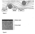
- the present invention concerns a use of an improved semi-permeable membrane in osmosis with properties adapted to the object, and/or membrane modules with reduced loss of energy, as stated in the preamble of claim 1. More detailed the invention concerns a use of a semi-permeable membrane consisting of one thin layer of a non-porous material (the diffusion skin), and one or more layers of a porous material (the porous layer).
- a plant as stated in the preamble of claim 12, for providing electric power through use of osmotic hydraulic elevated pressure is also described.
- US 4,283,913 comprises a saturated non-convective water reservoir which captures solar energy and which is used as a separation unit in combination with reverse electro dialysis or pressure retarded osmosis for energy production. From the water reservoir which partly can separate a solution, a higher concentrated stream and a less concentrated stream is passed into two chambers separated with a semi-permeable membrane. Parts of the energy which is created by permeation of the stream with lower concentration through the membrane and the subsequent mixing of the two mentioned streams are transformed into energy before the streams are returned to the water reservoir.
- US 3,906,250 discloses a method and apparatus for generating power by utilizing pressure retarded osmosis.
- a first liquid having a relatively high osmotic pressure is introduced at a relatively high hydraulic pressure into a first pathway in which it contacts one face of a semi-permeable membrane, and a second liquid having a lower osmotic pressure is introduced at lower hydraulic pressure into a second pathway in which it contacts the opposite face of the membrane.
- the hydraulic pressure difference between the liquids on the opposite faces of the membrane is maintained at a value which is less than the osmotic pressure difference between the liquids.
- Part of the second liquid passes by pressure-retarded osmosis through the semi-permeable membrane, forming a pressurized mixed solution of greater volume than that of the first liquid introduced into the first pathway.
- the potential energy stored in the pressurized mixed solution is then converted into useful energy, such as electrical or mechanical power.
- the first and second liquids are recovered by separating from the mixed solution a quantity of the second liquid equal to the quantity which passed through the membrane, the original temperatures of the so-recovered first and second liquids are restored, the original hydraulic pressure difference is reapplied between the recovered first and second liquids, and the recovered first and second liquids are then recycled through the first and second pathways.
- EP-0,882,493-A2 discloses a method for transferring mass between a flow of a first fluid in a gas phase such as combustion flue gas, and a flow of a second fluid in a liquid phase, where the first fluid is contacted with the outer surface of porous (semi-permeable) membranes, e.g. polytetrafluoro-ethylene (PTFE, Teflon) membranes, in the form of hollow fibres having gas-containing pores and contacting the second fluid with the inner surface of the membranes.
- porous membranes e.g. polytetrafluoro-ethylene (PTFE, Teflon) membranes
- PTFE polytetrafluoro-ethylene
- Useful membranes for such gas diffusion operation have a porosity (e)of at least 0.50, a mass transfer coefficient of e.g.
- the energy potential can in principle be utilized by several technical methods where the energy can be recovered as i.e. steam pressure and stretching of polymers.
- Two of the technical methods are using semi-permeable membranes, and these are reverse electro dialysis (energy potential as electrical DC voltage) and pressure retarded osmosis, PRO. (energy potential as water pressure).
- the actual potential for amounts of power seems to be 25 - 50% of the water power which today has been developed in Norway.
- Power plants based on the present invention do not lead to significant emissions into the air or water. Further this form of energy is fully renewable, and is only using natural water as driving force in the same manner as conventional water power plants.
- the object of the present invention is to make possible commercial utilization of salt power on a bigger scale.
- An important feature of the present invention is that most of the salt gradient in the membrane is localized in the same layer - the diffusion skin - as the flow resistance. Further the present patent application also consists of a porous carrier material for the diffusion skin with no resistance worth mentioning against water transport and salt diffusion. This is not satisfactorily achieved in existing membranes designed for filtering (reverse osmosis)/pressure retarded osmosis, PRO. In the present invention salt therefore does not appear in unfavourably high concentrations in parts of the membrane other than the diffusion skin. According to the present invention membranes with particular inner structures are also important. Further the concentration polarization of salt on the sea water side of the membranes is reduced compared to conventional membranes.
- the present invention describes semi-permeabie membranes or membrane modules in which the membranes include a thin diffusion skin with natural osmotic properties, and the rest of the membrane has an increased porosity, so that salt is not collected here (the porous layer).
- the membrane is suitably configured for pressure retarded osmosis.
- the value of S is related to a wetted membrane.
- the value of the structure parameter S and thereby the inner structure of the membrane is decisive for its efficiency in pressure retarded osmosis.
- the structure should have only one thin and non-porous layer wherein salt has considerably lower diffusion velocity than water.
- the other layers must all be porous so that salt and water can be transported with as little resistance as possible.
- Usually several porous layers are present to give the membrane the correct mechanical properties and/or as a result of the production method. In those cases where the diffusion skin lies between two or more porous layers, or the membrane is laterally reversed in relation to fresh water and salt water, the expressions will be more complicated, but the following discussion will be valid in the same manner.
- the structure parameter S should have a value of 0.0015 or lower.
- the thickness of the membrane is less than 150 ⁇ m, preferably less than 100 ⁇ m.
- the average value for porosity, ⁇ , in the porous layer in the present invention is more than 50%.
- the semi-permeable membrane has a tortuosity, ⁇ , which is less than 2,5.
- the permeability for salt, B is less than 3 ⁇ 10 -8 m/s, and the water permeability, A, is more than 1 ⁇ 10 -11 m/s Pa.
- the thickness of the diffusion film on the side containing lesser salt and the side containing more salt is less than 60 ⁇ m, preferably less than 30 ⁇ m.
- Membrane modules according to the present invention comprise flow breakers consisting of threads of polymers which are forming a net with a square or rhombic pattern. Further several membranes are packed together to modules (rolled up to spiral membranes) where the distance between adjacent membranes are from 0.4 to 0.8 mm.
- an elevated pressure is provided by osmosis (from salt gradients) in a system with pressure retarded osmosis through one or more semi-permeable membranes, which are built up of several layers, where at least one part of the osmotic pressure is maintained in the system.
- S is a structure parameter which is equal to or less than 0.0015 meter
- At least a part of the potential osmotic pressure between the two water streams is hydraulic transferred directly to the incoming salt containing feed stream.
- the amount of the salt containing feed stream is 1 - 3 times higher than the amount of the feed stream containing less salt, so that the ratio between the length of a flow path of the salt containing and the less salt containing stream is from 0.3 to 1.0.
- the distance between adjacent membranes is from 0.4 to 0.8 mm.
- the channels for the salt containing feed stream are 10-50% filled with one ore more flow breaking devices consisting of threads of polymer which form a net with square or rhombic pattern.
- the pressure in the salt containing feed stream on the membrane/membrane modules is in the range from 6 - 16 bars ((6-16) x 10 5 Pa).
- parallel fibres can be placed in layers between successive streams of a less salt containing feed stream and a salt containing feed stream. The above mentioned will then be a little altered, but the pressure will be the same.
- the invention concerns in addition a plant for providing electric power through use of elevated osmotic hydraulic pressure as described in claim 12.
- the plant includes one or more semi-preamble membranes or membrane modules where the membranes comprise a thin layer of non-porous material acting as the diffusion skin, and at least one layer of a porous material with a structure defined in claim 12, and at least a turbine with an electric generator. It preferably comprises a pressure exchange arrangement for direct hydraulic transmission of an osmotic pressure at elevated pressure branched off from an outlet of the membrane to an inlet thereof.
- the plant can be placed on the ground, or below the surface of the earth down to a level not below 200 meters.
- Pressure retarded osmosis is like all osmotic processes based on selective mass transport through membranes.
- a chamber with fresh water is separated from a chamber with sea water by a semi-permeable membrane. This membrane allows transport of water, but not of salt.
- Another possible design of a plant for pressure retarded osmosis is to build the plant buried 0 - 200 m, suitably 50 - 150 m, most preferably 120 m below ground level.
- fresh water is passed through pipelines downwards to the turbines, and from there into the low pressure side of the membranes.
- Sea water is passed into the high pressure side of the membranes which has been pressurized by hydrostatic power, and the sea water can circulate through the high pressure side with friction as the only loss.
- the fresh water will be transported through the membrane driven by the osmotic power, and leaves the plant mixed with sea water.
- the membranes can then be positioned as land based modules buried under ground level together with the turbines and other equipment. If the sea is more deep-set than the excavation the membrane modules could be placed directly in the sea.
- the skin of the membrane can possibly be located either against the sea water or the fresh water. Locating the diffusion skin against the fresh water side will have the advantage that the contaminations in the fresh water being more readily rejected on the membrane surface because the diffusion skin has far smaller pores in comparison with the porous carrier. Since there is a net volume stream moving in towards the membrane on the fresh water side, this volume stream will be able to transport different types of impurities which can lead to fouling of the membrane. On the other hand, a continuous water stream from the membrane on the water side will contribute to keeping the surface of the membrane clean.
- the diffusion skin lies on the sea water side since the overpressure will press the diffusion skin against the carrier. With the diffusion skin on the fresh water side there is a risk that the diffusion skin is loosened from the carrier, and the membrane can be destroyed.
- the parameters for the water permeability, A, and the salt permeability, B, are of high importance as to the performance of the membrane.
- the thickness, porosity and tortuosity of the carrier will not be of great importance to the energy production.
- the thickness of this diffusion film is a critical size for the energy production by pressure retarded osmosis. This size has to be determined experimentally from transport trials where flux data are adapted to the actual model. Theoretical calculations with a more complex transport model indicate a thickness of the diffusion film of approximately 0.000025 m.
- the thickness of the diffusion film on the surface of the membrane against the sea water side can be reduced by increasing the flow velocity on the sea water side, and by the use of devices which increase the stirring of the flowing sea water (turbulence promoters). Such efforts will increase the loss by friction during the flow of the sea water, and there will be an optimum point with regard to the sea water rate through a membrane module and the shaping of the membrane module.
- the concentration polarization of salt will be a small problem on the fresh water side in a good membrane module. This is a great advantage since the fresh water rate has to be low in parts of a good device as most of the fresh water is to be transported through the membrane and over to the sea water.
- sea water is pressurized before it flows through the membrane module. Then the sea water together with the fresh water which has been transported through the membrane, will expand through a turbine. The pump as well as the turbine will have an efficiency of less than 1, and energy will consequently be lost in these unity operations.
- pressure exchange can be used.
- pressure exchange the pressure in outgoing diluted sea water is used to compress incoming sea water. Only a quantity of water corresponding to the fresh water which flows through the membrane will pass through the turbine, and a far smaller turbine can therefore be used.
- the high pressure pump for pressurizing the sea water is completely eliminated.
- Table 1 Examples of possible power plants based on average water flow Example of rivers Water flow (m 3 /s) Power production (MW) Small local river 10 10 Namsen (Norway) 290 300 Glomma (Norway) 720 750 Rhine (Germany) 2 200 2 400 Mississippi (USA) 18 000 19 000
- the salt water rate, Q, out from the last cell defines the rate out of the process.
- the difference between out-rate and in-rate for salt water, and the pressure on the salt water side indicates the produced work.
- the exploitation ratio of fresh water is indicated by the difference between fresh water rate in and out in relation to fresh water rate in.
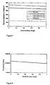
- the concentrations over the membrane from the inlet side and to the outlet are shown on figure 7 for a sea water pressure of 13 bars (1.3 x 10 6 Pa). Because the salt leakage through this membrane is small in this example, the increase of the salt concentration on the fresh water side is hardly noticeable, and reaches a discharge concentration of 0.5 moles/m 3 . Correspondingly the concentration polarization on the fresh water side can be fully neglected.
- the concentration polarization on the sea water side is considerable, and gives a concentration drop just below 100 moles/m 3 .
- concentration drop of almost 150 moles/m 3 over the carrier.
- the driving concentration difference over the skin of the membrane corresponds to the concentration difference between the surface of the skin against the sea water and the side of the adjacent porous layer which faces against the sea water, see figure 7 , and amounts to approximately 320 moles/m 3 , or barely 60% of the concentration difference between sea water and fresh water. This illustrates the importance of reducing the polarization effect. This is achieved by minimizing the thickness of the diffusion film on the sea water side (high flow velocity and good stirring), and the thickness of the carrier.
- Figure 8 shows the volume flux of water through the membrane as a function of dimensionless position from the inlet side. As the figure shows, the water flux changes relatively little, and the reason for this is that the driving concentration difference also is relatively constant along the membrane, see figure 7 .
Landscapes
- Engineering & Computer Science (AREA)
- Chemical & Material Sciences (AREA)
- Water Supply & Treatment (AREA)
- Chemical Kinetics & Catalysis (AREA)
- Combustion & Propulsion (AREA)
- Mechanical Engineering (AREA)
- General Engineering & Computer Science (AREA)
- Separation Using Semi-Permeable Membranes (AREA)
- Treatments Of Macromolecular Shaped Articles (AREA)
- Laminated Bodies (AREA)
- Cell Separators (AREA)
Claims (15)
- Verwendung einer semipermeablen Membran bei einer druckverzögerten Osmose zur Erzeugung von elektrischem Strom in einem Kraftwerk durch die Verwendung eines osmotischen hydraulischen Überdrucks, der durch die druckverzögerte Osmose erzeugt wird, zum Antreiben mindestens einer Turbine; wobei die Membran aus einer dünnen Schicht eines nicht porösen Materials, das als Diffusionshaut dient, und mindestens einer Schicht eines porösen Materials besteht, dadurch gekennzeichnet, dass
die poröse Schicht eine Struktur aufweist, bei der die Porosität ϕ, Dicke x(m) und Tortuosität τ in folgendem Verhältnis zueinander stehen
wobei S ein Strukturparameter mit einem Wert von 0,0015 m oder weniger ist, die Porosität ϕ mehr als 50% beträgt und die Tortuosität τ weniger als 2,5 beträgt und wobei die Membran eine Wasserpermeabilität von mehr als 1·10-11 m/s Pa und eine Salzpermeabilität von weniger als 3·10-8 m/s aufweist. - Verwendung nach Anspruch 1, dadurch gekennzeichnet, dass die Membran eine Dicke von weniger als 150 µm aufweist.
- Verwendung nach Anspruch 2, wobei die Membran eine Dicke von weniger als 100 µm aufweist.
- Verwendung nach einem der Ansprüche 1-3, dadurch gekennzeichnet, dass die Membran mehrere Membranen umfasst und zwischen den Membranen Strömungsbrecher umfasst, die aus Polymerfäden bestehen, die ein Netz mit einem quadratischen oder rhombischen Muster bilden.
- Verwendung nach einem der Ansprüche 1-4, dadurch gekennzeichnet, dass mehrere der Membranen unter Ausbildung von Modulen in Schichten zusammengepackt sind, wobei der Abstand zwischen benachbarten Membranen 0,4 und 0,8 mm beträgt.
- Verwendung nach einem der Ansprüche 1-5, dadurch gekennzeichnet, dass die Membran die Form von Hohlfasern mit einem Außendurchmesser von 0,05 bis 0,5 mm aufweist.
- Verwendung nach einem der Ansprüche 1-6, umfassend das Kontaktieren eines salzhaltigen ersten Wasserzuführungsstroms mit einem nicht porösen Material oder der Diffusionshaut der Membran, wobei gleichzeitig ein zweiter Wasserzuführungsstrom mit weniger Salz in Kontakt mit der porösen Schicht der Membran in Kontakt gebracht wird;
wobei das Wasser des Stroms mit weniger Salz auf natürliche Weise mittels Osmose durch die Membran getrieben wird und einen osmotischen hydraulischen Überdruck auf der Permeatseite erzeugt, sodass mindestens ein Teil des potenziellen osmotischen Drucks an der Membran direkt hydraulisch auf den einfließenden salzhaltigen Zuführungsstrom übertragen wird. - Verwendung nach Anspruch 7, dadurch gekennzeichnet, dass die Menge an salzhaltigem Zuführungsstrom ein- bis dreimal höher ist als die Menge an Zuführungsstrom mit weniger Salz.
- Verwendung nach Anspruch 7 oder Anspruch 8, dadurch gekennzeichnet, dass mehr als eine der Membranen verwendet wird und dass der Kanal des salzhaltigen Stroms zwischen den Membranen Strömungsbrecher umfasst, die aus Polymerfäden bestehen, die ein Netz mit einem quadratischen oder rhombischen Muster bilden, das den Kanal zu 10-50% füllt.
- Verwendung nach einem der Ansprüche 7-9, dadurch gekennzeichnet, dass das Verhältnis zwischen der Länge eines Strömungswegs des salzhaltigen Stroms und des Stroms mit weniger Salz 0,3 bis 1,0 beträgt.
- Verwendung nach einem der Ansprüche 7-9, dadurch gekennzeichnet, dass der Druck des salzhaltigen Zuführungsstroms, der durch die Membran oder das Membranmodul fließt, im Bereich 6-16 bar liegt.
- Anlage zur Bereitstellung von elektrischem Strom durch die Verwendung eines osmotischen hydraulischen Überdrucks, der durch druckverzögerte Osmose erzeugt wird, dadurch gekennzeichnet, dass die Anlage umfasst
mindestens eine semipermeable Membran, bestehend aus einer dünnen Schicht eines nicht porösen Materials, das als Diffusionshaut dient, und mindestens einer Schicht eines porösen Materials, dadurch gekennzeichnet, dass die poröse Schicht eine Struktur aufweist, bei der die Porosität ϕ, Dicke x(m) und Tortuosität τ in folgendem Verhältnis zueinander stehen
wobei S ein Strukturparameter mit einem Wert von 0,0015 m oder weniger ist, die Porosität ϕ mehr als 50% beträgt und die Tortuosität τ weniger als 2,5 beträgt und wobei die Membran eine Wasserpermeabilität von mehr als 1·10-11 m/s Pa und eine Salzpermeabilität von weniger als 3·10-8 m/s aufweist; und
mindestens eine Turbine. - Anlage nach Anspruch 12, wobei die Turbine einem Auslass der Membran nachgeordnet angeordnet ist und die weiterhin eine Druckaustauschvorrichtung für die direkte hydraulische Übertragung von osmotischem Druck bei Überdruck umfasst, die von einem Auslass der Membran zu einem Einlass davon abzweigt.
- Anlage nach Anspruch 13, dadurch gekennzeichnet, dass mindestens eine Strom erzeugende Turbine dem Auslass nachgeordnet und einem Ort, an dem die Druckübertragung von dem Auslass abzweigt, nachgeordnet angeordnet ist.
- Anlage nach Anspruch 12, dadurch gekennzeichnet, dass die Anlage 80-200 m unter dem Boden angeordnet ist; dass Süßwasser durch Rohre nach unten zu der mindestens einen Turbine, die dem Süßwassereinlass der Membran vorgeordnet ist, fließt; dass das Süßwasser weiterhin von der Turbine zu einer Unterdruckseite der Membran fließt; dass Salzwasser zu einer Überdruckseite der Membran fließt, wobei das Salzwasser durch hydrostatische Kraft unter Druck gesetzt worden ist; dass das Salzwasser durch die Überdruckseite der Membran zirkulieren darf; dass das Süßwasser mittels osmotischem Druck durch die Membran transportiert wird; und dass das die Anlage verlassende Wasser das mit Salzwasser gemischte Süßwasser ist.
Priority Applications (1)
| Application Number | Priority Date | Filing Date | Title |
|---|---|---|---|
| EP09176193A EP2153881A1 (de) | 2000-08-04 | 2001-07-20 | Halbdurchlässige Membran |
Applications Claiming Priority (3)
| Application Number | Priority Date | Filing Date | Title |
|---|---|---|---|
| NO20003977 | 2000-08-04 | ||
| NO20003977A NO314575B1 (no) | 2000-08-04 | 2000-08-04 | Semipermeabel membran og fremgangsmate for tilveiebringelse av elektrisk kraft samt en anordning |
| PCT/NO2001/000314 WO2002013955A1 (en) | 2000-08-04 | 2001-07-20 | Semi-permeable membrane, method for providing electric power and a device |
Related Child Applications (2)
| Application Number | Title | Priority Date | Filing Date |
|---|---|---|---|
| EP08019660.3 Division-Into | 2008-11-11 | ||
| EP09176193.2 Division-Into | 2009-11-17 |
Publications (2)
| Publication Number | Publication Date |
|---|---|
| EP1315554A1 EP1315554A1 (de) | 2003-06-04 |
| EP1315554B1 true EP1315554B1 (de) | 2010-11-10 |
Family
ID=19911456
Family Applications (2)
| Application Number | Title | Priority Date | Filing Date |
|---|---|---|---|
| EP01961437A Expired - Lifetime EP1315554B1 (de) | 2000-08-04 | 2001-07-20 | Verwendung einer semipermeablen membran bei einer druckverzögerten osmose zur erzeugung von elektrischen strom, und anlage. |
| EP09176193A Withdrawn EP2153881A1 (de) | 2000-08-04 | 2001-07-20 | Halbdurchlässige Membran |
Family Applications After (1)
| Application Number | Title | Priority Date | Filing Date |
|---|---|---|---|
| EP09176193A Withdrawn EP2153881A1 (de) | 2000-08-04 | 2001-07-20 | Halbdurchlässige Membran |
Country Status (12)
| Country | Link |
|---|---|
| US (3) | US7563370B2 (de) |
| EP (2) | EP1315554B1 (de) |
| JP (1) | JP5422809B2 (de) |
| AT (1) | ATE487532T1 (de) |
| AU (1) | AU2001282698A1 (de) |
| CA (1) | CA2418329C (de) |
| DE (1) | DE60143439D1 (de) |
| DK (1) | DK1315554T3 (de) |
| ES (1) | ES2355547T3 (de) |
| NO (1) | NO314575B1 (de) |
| PT (1) | PT1315554E (de) |
| WO (1) | WO2002013955A1 (de) |
Cited By (1)
| Publication number | Priority date | Publication date | Assignee | Title |
|---|---|---|---|---|
| WO2023081881A1 (en) * | 2021-11-07 | 2023-05-11 | Sage Geosystems Inc. | Geopressure and geothermal power system |
Families Citing this family (55)
| Publication number | Priority date | Publication date | Assignee | Title |
|---|---|---|---|---|
| NO314575B1 (no) * | 2000-08-04 | 2003-04-14 | Statkraft Sf | Semipermeabel membran og fremgangsmate for tilveiebringelse av elektrisk kraft samt en anordning |
| NO20016012L (no) * | 2001-12-07 | 2003-06-10 | Statkraft Sf | Hydrofil semipermeabel membran |
| JP5468253B2 (ja) * | 2005-05-20 | 2014-04-09 | アクアポリン アー/エス | 水を濾過するための膜、並びに当該膜を利用した方法及び装置 |
| CN101267875B (zh) | 2005-09-20 | 2013-02-06 | 水通道蛋白有限公司 | 用于产生盐度能的含有水通道蛋白的仿生水膜 |
| NO329120B1 (no) * | 2005-12-22 | 2010-08-30 | Statkraft Dev As | Fremgangsmate og system for a utfore vedlikehold pa en membran som har halvgjennomtrengelige egenskaper |
| EP2021586B1 (de) | 2006-05-12 | 2015-02-25 | Energy Recovery, Inc. | Hybrides ro-/pro-system |
| GB0621247D0 (en) * | 2006-10-25 | 2006-12-06 | Univ Surrey | Separation process |
| WO2008060435A2 (en) * | 2006-11-09 | 2008-05-22 | Yale University | Osmotic heat engine |
| US20100192575A1 (en) * | 2007-09-20 | 2010-08-05 | Abdulsalam Al-Mayahi | Process and systems |
| JP4870648B2 (ja) * | 2007-10-25 | 2012-02-08 | 株式会社荏原製作所 | 動力回収システム |
| CA2745702A1 (en) * | 2008-12-03 | 2010-06-10 | Oasys Water, Inc. | Utility scale osmotic grid storage |
| US20100155333A1 (en) * | 2008-12-18 | 2010-06-24 | Chevron U.S.A., Inc. | Process for dewatering an aqueous organic solution |
| US20100212319A1 (en) * | 2009-02-24 | 2010-08-26 | Mark Donovan | Method and apparatus for generating power utilizing forward osmosis |
| US20100282656A1 (en) * | 2009-05-05 | 2010-11-11 | Cath Tzahi Y | Osmotic barrier system and method |
| US20110000861A1 (en) * | 2009-07-06 | 2011-01-06 | Bear Creek Services, LLC. | Portable and Scalable Water Reclamation System and Method |
| US8545701B2 (en) * | 2009-08-18 | 2013-10-01 | Maher Isaac Kelada | Induced symbiotic osmosis [ISO] for salinity power generation |
| US9186627B2 (en) | 2009-08-24 | 2015-11-17 | Oasys Water, Inc. | Thin film composite heat exchangers |
| AU2010289795B2 (en) | 2009-08-24 | 2015-09-24 | Oasys Water LLC | Forward osmosis membranes |
| BR112012010232A2 (pt) * | 2009-10-28 | 2017-07-04 | Oasys Water Inc | processos de separação por osmose direta |
| US9044711B2 (en) | 2009-10-28 | 2015-06-02 | Oasys Water, Inc. | Osmotically driven membrane processes and systems and methods for draw solute recovery |
| WO2011069050A1 (en) | 2009-12-03 | 2011-06-09 | Yale University | High flux thin-film composite forward osmosis and pressure-retarded osmosis membranes |
| US8695343B2 (en) * | 2009-12-04 | 2014-04-15 | General Electric Company | Economical and sustainable disposal of zero liquid discharge salt byproduct |
| US9023210B2 (en) * | 2009-12-07 | 2015-05-05 | Fluid Equipment Development Company, Llc | Method and apparatus for osmotic power generation |
| SG184918A1 (en) | 2010-04-22 | 2012-11-29 | Univ Nanyang Tech | Method of preparing a nanocomposite membrane and nanocomposite membranes prepared thereof |
| US12384699B2 (en) | 2010-05-21 | 2025-08-12 | Crosstek Holding Company Llc | Self-assembled surfactant structures |
| JP6031660B2 (ja) * | 2010-05-21 | 2016-11-24 | ゼットナノ エルエルシーzNano LLC | 自己集合界面活性剤構造 |
| JP2011255312A (ja) * | 2010-06-09 | 2011-12-22 | Fujifilm Corp | 順浸透装置および順浸透法 |
| WO2012002263A1 (ja) * | 2010-06-28 | 2012-01-05 | 協和機電工業株式会社 | 中空糸型正浸透膜 |
| JP6276590B2 (ja) * | 2010-09-30 | 2018-02-07 | ポリフェラ・インコーポレイテッド | 正浸透用の薄膜複合膜及びその作製方法 |
| WO2012135065A2 (en) | 2011-03-25 | 2012-10-04 | Porifera, Inc. | Membranes having aligned 1-d nanoparticles in a matrix layer for improved fluid separation |
| US20140284929A1 (en) * | 2011-03-30 | 2014-09-25 | Toray Industries, Inc. | Concentration difference power generation device and method for operating same |
| KR20120119043A (ko) | 2011-04-20 | 2012-10-30 | 삼성전자주식회사 | 분리막, 이의 제조 방법 및 이를 포함하는 복합막 |
| WO2013033082A1 (en) * | 2011-08-31 | 2013-03-07 | Oasys Water, Inc. | Osmotic heat engine |
| US9339765B2 (en) | 2011-09-16 | 2016-05-17 | General Electric Company | Electrodialysis method and apparatus for passivating scaling species |
| US9227360B2 (en) | 2011-10-17 | 2016-01-05 | Porifera, Inc. | Preparation of aligned nanotube membranes for water and gas separation applications |
| CA2892085C (en) | 2011-11-22 | 2022-07-26 | Znano Llc | Filter comprising porous plastic material coated with hydophilic coating |
| WO2013164541A2 (fr) * | 2012-05-02 | 2013-11-07 | Total Sa | Production d'energie par osmose directe |
| CN105142765A (zh) * | 2012-11-12 | 2015-12-09 | 纳格瑞美布拉尼斯公司 | 在用于渗透驱动的膜过程的膜中减少离子交换和反向盐流动现象的方法 |
| KR102162325B1 (ko) | 2012-12-21 | 2020-10-06 | 포리페라 인코포레이티드 | 적층된 멤브레인 및 스페이서를 이용하는 분리를 위한 분리 시스템, 요소 및 방법 |
| GB201300465D0 (en) | 2013-01-11 | 2013-02-27 | Aquaporin As | A hollow fiber module having tfc-aquaporin modified membranes |
| US8974668B2 (en) | 2013-02-15 | 2015-03-10 | Maher Isaac Kelada | Hollow fiber membrane element and methods of making same |
| DK177696B1 (en) | 2013-02-25 | 2014-03-17 | Aquaporin As | Systems for water extraction |
| EP2969145B1 (de) | 2013-03-15 | 2024-08-07 | Porifera Inc. | Fortschritte bei osmosegesteuerten membransystemen mit mehrstufiger reinigung |
| CN103172189A (zh) * | 2013-04-09 | 2013-06-26 | 中国科学院化学研究所 | 一种利用渗透能发电的装置 |
| SG11201509816QA (en) * | 2013-06-19 | 2015-12-30 | Univ Singapore | Thin film composite hollow fibers for osmotic power generation |
| JP6169019B2 (ja) * | 2014-02-28 | 2017-07-26 | 株式会社東芝 | 循環型浸透圧発電のための作業媒体、循環型浸透圧発電システムおよび方法、並びに作業媒体の相制御方法 |
| WO2016070103A1 (en) | 2014-10-31 | 2016-05-06 | Porifera, Inc. | Supported carbon nanotube membranes and their preparation methods |
| WO2016159531A1 (ko) * | 2015-04-01 | 2016-10-06 | 한국에너지기술연구원 | 격자형 삼투압장치 |
| HRP20200915T4 (hr) | 2015-06-24 | 2025-04-11 | Porifera, Inc. | Postupci za isušivanje alkoholnih otopina putem napredne osmoze i srodni sustavi |
| EP3263896A1 (de) * | 2016-06-28 | 2018-01-03 | Ecole Polytechnique Fédérale de Lausanne (EPFL) | Osmotische stromerzeugung |
| EP3559197B1 (de) | 2016-12-23 | 2025-03-26 | Porifera, Inc. | Entfernung von bestandteilen alkoholischer lösungen mittels vorwärtsosmose und zugehörige systeme |
| WO2019012164A1 (es) | 2017-07-12 | 2019-01-17 | Brinergy Tech., S.L. | Sistema y procedimiento para la depuración de aguas |
| WO2019027969A1 (en) * | 2017-07-31 | 2019-02-07 | Oakland University | Fluid system |
| NO345299B1 (no) * | 2018-05-30 | 2020-12-07 | Geir Anders Evensen | Undervannssaltkraftverk |
| JP7713459B2 (ja) * | 2020-09-03 | 2025-07-25 | 株式会社クラレ | 複合半透膜 |
Family Cites Families (30)
| Publication number | Priority date | Publication date | Assignee | Title |
|---|---|---|---|---|
| NL271831A (de) * | 1960-11-29 | |||
| US3344214A (en) * | 1964-03-25 | 1967-09-26 | Univ California | Methods of preparing a semipermeable membrane |
| US3423491A (en) * | 1964-09-02 | 1969-01-21 | Dow Chemical Co | Permselective hollow fibers and method of making |
| US3497072A (en) * | 1966-05-02 | 1970-02-24 | Aerojet General Co | Reverse osmosis membrane and method of manufacture |
| US3332894A (en) * | 1966-12-06 | 1967-07-25 | Paul A Cantor | Polyvinyl carbonate desalination membrane and a method of producing the same |
| US3423310A (en) * | 1967-03-06 | 1969-01-21 | Us Agriculture | Osmotic processes and apparatus |
| US3709774A (en) * | 1970-05-13 | 1973-01-09 | Gen Electric | Preparation of asymmetric polymer membranes |
| US3763055A (en) * | 1971-07-07 | 1973-10-02 | Us Interior | Microporous support for reverse osmosis membranes |
| US3906250A (en) | 1973-07-03 | 1975-09-16 | Univ Ben Gurion | Method and apparatus for generating power utilizing pressure-retarded-osmosis |
| US3978344A (en) | 1973-11-12 | 1976-08-31 | Jellinek Hans H G | Osmosis process for producing energy |
| IL51541A (en) * | 1977-02-25 | 1979-05-31 | Univ Ben Gurion | Method and apparatus for generating power utilizing pressuure retarded osmosis |
| USRE32144E (en) * | 1977-03-28 | 1986-05-13 | Reverse osmosis method and apparatus | |
| US5130025A (en) * | 1978-04-20 | 1992-07-14 | Unisearch Limited | Membrane separation and purification of compounds |
| US4283913A (en) | 1978-12-12 | 1981-08-18 | Intertechnology/Solar Corporation | Utilization of saturated solar ponds |
| JPS5853684A (ja) * | 1981-09-28 | 1983-03-30 | Kajima Corp | 浸透圧を利用した発電方法 |
| JPS6258063A (ja) * | 1985-09-06 | 1987-03-13 | Agency Of Ind Science & Technol | 濃度差発電用浸透装置 |
| US5123481A (en) * | 1986-07-09 | 1992-06-23 | Walter F. Albers | Method and apparatus for simultaneous heat and mass transfer |
| US4902417A (en) * | 1988-06-14 | 1990-02-20 | Desalination Systems, Inc. | Spiral-wound membrane cartridge with ribbed and spaced carrier layer |
| US4966708A (en) * | 1989-02-24 | 1990-10-30 | Oklejas Robert A | Power recovery pump turbine |
| US5037555A (en) * | 1990-07-09 | 1991-08-06 | Texaco Inc. | Desalination of water |
| SE470479B (sv) * | 1992-09-28 | 1994-05-24 | Electrolux Ab | Membranmodul och förfarande för dess framställning |
| DE69528652D1 (de) | 1994-06-22 | 2002-11-28 | Fls Miljoe As Valby | Vorrichtung zur massenübertragung |
| WO2000000268A1 (en) * | 1998-06-29 | 2000-01-06 | Microban Products Company | Antimicrobial semi-permeable membranes |
| ES2300149T3 (es) * | 1998-07-21 | 2008-06-01 | Toray Industries, Inc. | Procedimiento para la inhibicion del desarrollo de bacterias en la vecindad de una membrana de separacion y tecnica de esterilizacion de esta. |
| FR2786710B1 (fr) * | 1998-12-04 | 2001-11-16 | Ceramiques Tech Soc D | Membrane comprenant un support poreux et une couche d'un tamis modeculaire et son procede de preparation |
| ATE245472T1 (de) * | 1999-02-26 | 2003-08-15 | United States Filter Corp | Verfahren und vorrichtung zur prüfung von membranfiltern |
| US6313545B1 (en) * | 1999-03-10 | 2001-11-06 | Wader, Llc. | Hydrocratic generator |
| US6811842B1 (en) * | 1999-06-29 | 2004-11-02 | The Procter & Gamble Company | Liquid transport member for high flux rates between two port regions |
| US6579457B1 (en) * | 1999-06-29 | 2003-06-17 | The Procter & Gamble Company | Liquid transport member for high flux rates between a port region and an opening |
| NO314575B1 (no) * | 2000-08-04 | 2003-04-14 | Statkraft Sf | Semipermeabel membran og fremgangsmate for tilveiebringelse av elektrisk kraft samt en anordning |
-
2000
- 2000-08-04 NO NO20003977A patent/NO314575B1/no not_active IP Right Cessation
-
2001
- 2001-07-20 US US10/343,735 patent/US7563370B2/en not_active Expired - Fee Related
- 2001-07-20 PT PT01961437T patent/PT1315554E/pt unknown
- 2001-07-20 DE DE60143439T patent/DE60143439D1/de not_active Expired - Lifetime
- 2001-07-20 EP EP01961437A patent/EP1315554B1/de not_active Expired - Lifetime
- 2001-07-20 WO PCT/NO2001/000314 patent/WO2002013955A1/en not_active Ceased
- 2001-07-20 ES ES01961437T patent/ES2355547T3/es not_active Expired - Lifetime
- 2001-07-20 DK DK01961437.9T patent/DK1315554T3/da active
- 2001-07-20 AT AT01961437T patent/ATE487532T1/de not_active IP Right Cessation
- 2001-07-20 JP JP2002519087A patent/JP5422809B2/ja not_active Expired - Fee Related
- 2001-07-20 AU AU2001282698A patent/AU2001282698A1/en not_active Abandoned
- 2001-07-20 CA CA002418329A patent/CA2418329C/en not_active Expired - Fee Related
- 2001-07-20 EP EP09176193A patent/EP2153881A1/de not_active Withdrawn
-
2008
- 2008-02-04 US US12/068,185 patent/US7566402B2/en not_active Expired - Fee Related
-
2009
- 2009-06-22 US US12/488,914 patent/US20090250392A1/en not_active Abandoned
Non-Patent Citations (4)
| Title |
|---|
| AMYX J.W. ET AL: "Petroleum Reservoir Engineering", 1960, MCCRAW-HILL * |
| DULLIEN F.A.L.: "Porous Media Fluid Transport and Pore Structure", 1979, ACADEMIC PRESS * |
| LEE K.L. ET AL: "Membranes for power generation by pressure-retarded osmosis", JOURNAL OF MEMBRANE SCIENCE, vol. 8, 1981, pages 141 - 171 * |
| LOEB S.: "Energy production at the Dead Sea by pressure-retarded osmosis: challenge or chimera?", DESALINATION, no. 120, 1998, pages 247 - 262 * |
Cited By (1)
| Publication number | Priority date | Publication date | Assignee | Title |
|---|---|---|---|---|
| WO2023081881A1 (en) * | 2021-11-07 | 2023-05-11 | Sage Geosystems Inc. | Geopressure and geothermal power system |
Also Published As
| Publication number | Publication date |
|---|---|
| DE60143439D1 (de) | 2010-12-23 |
| DK1315554T3 (da) | 2011-01-17 |
| US7566402B2 (en) | 2009-07-28 |
| JP2004505764A (ja) | 2004-02-26 |
| AU2001282698A1 (en) | 2002-02-25 |
| PT1315554E (pt) | 2011-02-07 |
| EP2153881A1 (de) | 2010-02-17 |
| EP1315554A1 (de) | 2003-06-04 |
| US20090250392A1 (en) | 2009-10-08 |
| US7563370B2 (en) | 2009-07-21 |
| WO2002013955A1 (en) | 2002-02-21 |
| CA2418329A1 (en) | 2002-02-21 |
| NO20003977D0 (no) | 2000-08-04 |
| CA2418329C (en) | 2010-02-02 |
| NO20003977L (no) | 2002-02-05 |
| US20080210634A1 (en) | 2008-09-04 |
| US20080169723A1 (en) | 2008-07-17 |
| NO314575B1 (no) | 2003-04-14 |
| ATE487532T1 (de) | 2010-11-15 |
| ES2355547T3 (es) | 2011-03-28 |
| JP5422809B2 (ja) | 2014-02-19 |
Similar Documents
| Publication | Publication Date | Title |
|---|---|---|
| EP1315554B1 (de) | Verwendung einer semipermeablen membran bei einer druckverzögerten osmose zur erzeugung von elektrischen strom, und anlage. | |
| EP2083937B1 (de) | Osmosewärmekraftmaschine | |
| Post et al. | Salinity-gradient power: Evaluation of pressure-retarded osmosis and reverse electrodialysis | |
| McGinnis et al. | A novel ammonia–carbon dioxide osmotic heat engine for power generation | |
| Hickenbottom et al. | Assessing the current state of commercially available membranes and spacers for energy production with pressure retarded osmosis | |
| Charcosset | A review of membrane processes and renewable energies for desalination | |
| Xiao et al. | Integration of desalination and energy conversion in a thermo-osmotic system using low-grade heat: Performance analysis and techno-economic evaluation | |
| EP2507515B1 (de) | Ökonomische und nachhaltige entsorgung eines salznebenprodukts ohne flüssigkeitsablass | |
| Wang et al. | Feasibility research of potable water production via solar-heated hollow fiber membrane distillation system | |
| KR102598064B1 (ko) | 전력 생산 공정 | |
| Wang et al. | Energy generation from osmotic pressure difference between the low and high salinity water by pressure retarded osmosis | |
| Tran et al. | System scaling approach and thermoeconomic analysis of a pressure retarded osmosis system for power production with hypersaline draw solution: a Great Salt Lake case study | |
| Al-Anzi et al. | Lab scale assessment of power generation using pressure retarded osmosis from wastewater treatment plants in the state of Kuwait | |
| Achilli et al. | Pressure retarded osmosis: Applications | |
| Liu et al. | Current patents of forward osmosis membrane process | |
| CN112709678B (zh) | 通过增压渗透和协同效应产生大型可再生能源的方法和装置 | |
| WO2003047733A1 (en) | Hydrophile semipermeable membrane | |
| Tran et al. | Performance analysis for pressure retarded osmosis: Experimentation with high pressure difference and varying flow rate, considering exposed membrane area | |
| Cath | Osmotic power generation | |
| Thorsen et al. | Finding hidden energy in membrane processes | |
| Bouzid-Lagha et al. | Optimization of Energy Cost Seawater Desalinization by Reverse Osmosis: Case of Bousmail Station in Algeria | |
| Terashima et al. | Permeation characteristics of fresh water in hollow fiber membrane module for pressure retarded osmosis | |
| Mehta et al. | Salinity gradient energy conversion | |
| Wicaksana et al. | Reverse osmosis beneficiation |
Legal Events
| Date | Code | Title | Description |
|---|---|---|---|
| PUAI | Public reference made under article 153(3) epc to a published international application that has entered the european phase |
Free format text: ORIGINAL CODE: 0009012 |
|
| 17P | Request for examination filed |
Effective date: 20030212 |
|
| AK | Designated contracting states |
Designated state(s): AT BE CH CY DE DK ES FI FR GB GR IE IT LI LU MC NL PT SE TR |
|
| AX | Request for extension of the european patent |
Extension state: AL LT LV MK RO SI |
|
| 17Q | First examination report despatched |
Effective date: 20030919 |
|
| RAP1 | Party data changed (applicant data changed or rights of an application transferred) |
Owner name: STATKRAFT DEVELOPMENT AS |
|
| RTI1 | Title (correction) |
Free format text: SEMI-PERMEABLE MEMBRANE FOR USE IN OSMOSIS, AND METHOD AND PLANT FOR PROVIDING ELEVATED PRESSURE BY OSMOSIS TO CREATE POWER |
|
| GRAP | Despatch of communication of intention to grant a patent |
Free format text: ORIGINAL CODE: EPIDOSNIGR1 |
|
| GRAS | Grant fee paid |
Free format text: ORIGINAL CODE: EPIDOSNIGR3 |
|
| GRAA | (expected) grant |
Free format text: ORIGINAL CODE: 0009210 |
|
| RTI1 | Title (correction) |
Free format text: USE OF A SEMI-PERMEABLE MEMBRANE IN PRESSURE RETARDED OSMOSIS FOR PROVIDING ELECTRIC POWER, AND PLANT. |
|
| AK | Designated contracting states |
Kind code of ref document: B1 Designated state(s): AT BE CH CY DE DK ES FI FR GB GR IE IT LI LU MC NL PT SE TR |
|
| REG | Reference to a national code |
Ref country code: GB Ref legal event code: FG4D |
|
| REG | Reference to a national code |
Ref country code: CH Ref legal event code: EP |
|
| REG | Reference to a national code |
Ref country code: IE Ref legal event code: FG4D |
|
| REF | Corresponds to: |
Ref document number: 60143439 Country of ref document: DE Date of ref document: 20101223 Kind code of ref document: P |
|
| REG | Reference to a national code |
Ref country code: DK Ref legal event code: T3 |
|
| REG | Reference to a national code |
Ref country code: PT Ref legal event code: SC4A Free format text: AVAILABILITY OF NATIONAL TRANSLATION Effective date: 20110131 |
|
| REG | Reference to a national code |
Ref country code: SE Ref legal event code: TRGR |
|
| REG | Reference to a national code |
Ref country code: NL Ref legal event code: T3 |
|
| REG | Reference to a national code |
Ref country code: ES Ref legal event code: FG2A Ref document number: 2355547 Country of ref document: ES Kind code of ref document: T3 Effective date: 20110328 |
|
| REG | Reference to a national code |
Ref country code: GR Ref legal event code: EP Ref document number: 20110400306 Country of ref document: GR Effective date: 20110317 |
|
| PG25 | Lapsed in a contracting state [announced via postgrant information from national office to epo] |
Ref country code: CY Free format text: LAPSE BECAUSE OF FAILURE TO SUBMIT A TRANSLATION OF THE DESCRIPTION OR TO PAY THE FEE WITHIN THE PRESCRIBED TIME-LIMIT Effective date: 20101110 Ref country code: FI Free format text: LAPSE BECAUSE OF FAILURE TO SUBMIT A TRANSLATION OF THE DESCRIPTION OR TO PAY THE FEE WITHIN THE PRESCRIBED TIME-LIMIT Effective date: 20101110 Ref country code: AT Free format text: LAPSE BECAUSE OF FAILURE TO SUBMIT A TRANSLATION OF THE DESCRIPTION OR TO PAY THE FEE WITHIN THE PRESCRIBED TIME-LIMIT Effective date: 20101110 |
|
| PG25 | Lapsed in a contracting state [announced via postgrant information from national office to epo] |
Ref country code: BE Free format text: LAPSE BECAUSE OF FAILURE TO SUBMIT A TRANSLATION OF THE DESCRIPTION OR TO PAY THE FEE WITHIN THE PRESCRIBED TIME-LIMIT Effective date: 20101110 |
|
| PLBE | No opposition filed within time limit |
Free format text: ORIGINAL CODE: 0009261 |
|
| STAA | Information on the status of an ep patent application or granted ep patent |
Free format text: STATUS: NO OPPOSITION FILED WITHIN TIME LIMIT |
|
| 26N | No opposition filed |
Effective date: 20110811 |
|
| PGFP | Annual fee paid to national office [announced via postgrant information from national office to epo] |
Ref country code: DK Payment date: 20110720 Year of fee payment: 11 |
|
| PGFP | Annual fee paid to national office [announced via postgrant information from national office to epo] |
Ref country code: SE Payment date: 20110722 Year of fee payment: 11 |
|
| REG | Reference to a national code |
Ref country code: DE Ref legal event code: R097 Ref document number: 60143439 Country of ref document: DE Effective date: 20110811 |
|
| PG25 | Lapsed in a contracting state [announced via postgrant information from national office to epo] |
Ref country code: MC Free format text: LAPSE BECAUSE OF NON-PAYMENT OF DUE FEES Effective date: 20110731 |
|
| REG | Reference to a national code |
Ref country code: CH Ref legal event code: PL |
|
| PG25 | Lapsed in a contracting state [announced via postgrant information from national office to epo] |
Ref country code: CH Free format text: LAPSE BECAUSE OF NON-PAYMENT OF DUE FEES Effective date: 20110731 Ref country code: LI Free format text: LAPSE BECAUSE OF NON-PAYMENT OF DUE FEES Effective date: 20110731 |
|
| REG | Reference to a national code |
Ref country code: SE Ref legal event code: EUG |
|
| REG | Reference to a national code |
Ref country code: DK Ref legal event code: EBP |
|
| PG25 | Lapsed in a contracting state [announced via postgrant information from national office to epo] |
Ref country code: SE Free format text: LAPSE BECAUSE OF NON-PAYMENT OF DUE FEES Effective date: 20120721 |
|
| PG25 | Lapsed in a contracting state [announced via postgrant information from national office to epo] |
Ref country code: LU Free format text: LAPSE BECAUSE OF NON-PAYMENT OF DUE FEES Effective date: 20110720 |
|
| PG25 | Lapsed in a contracting state [announced via postgrant information from national office to epo] |
Ref country code: DK Free format text: LAPSE BECAUSE OF NON-PAYMENT OF DUE FEES Effective date: 20120731 |
|
| PGFP | Annual fee paid to national office [announced via postgrant information from national office to epo] |
Ref country code: TR Payment date: 20130624 Year of fee payment: 13 |
|
| PGFP | Annual fee paid to national office [announced via postgrant information from national office to epo] |
Ref country code: DE Payment date: 20130722 Year of fee payment: 13 Ref country code: ES Payment date: 20130729 Year of fee payment: 13 Ref country code: IE Payment date: 20130726 Year of fee payment: 13 Ref country code: NL Payment date: 20130719 Year of fee payment: 13 Ref country code: GR Payment date: 20130729 Year of fee payment: 13 |
|
| REG | Reference to a national code |
Ref country code: DE Ref legal event code: R082 Ref document number: 60143439 Country of ref document: DE Representative=s name: PLOUGMANN & VINGTOFT A/S, DK |
|
| REG | Reference to a national code |
Ref country code: NL Ref legal event code: TD Effective date: 20131106 |
|
| PGFP | Annual fee paid to national office [announced via postgrant information from national office to epo] |
Ref country code: FR Payment date: 20130722 Year of fee payment: 13 Ref country code: GB Payment date: 20130719 Year of fee payment: 13 |
|
| REG | Reference to a national code |
Ref country code: PT Ref legal event code: PC4A Owner name: STATKRAFT AS, NO Effective date: 20131125 |
|
| REG | Reference to a national code |
Ref country code: GB Ref legal event code: 732E Free format text: REGISTERED BETWEEN 20131114 AND 20131120 |
|
| REG | Reference to a national code |
Ref country code: DE Ref legal event code: R081 Ref document number: 60143439 Country of ref document: DE Owner name: STATKRAFT AS, NO Free format text: FORMER OWNER: STATKRAFT DEVELOPMENT AS, OSLO, NO Effective date: 20131104 Ref country code: DE Ref legal event code: R082 Ref document number: 60143439 Country of ref document: DE Representative=s name: PLOUGMANN & VINGTOFT A/S, DK Effective date: 20131104 Ref country code: DE Ref legal event code: R082 Ref document number: 60143439 Country of ref document: DE Representative=s name: PLOUGMANN VINGTOFT A/S, DK Effective date: 20131104 |
|
| PGFP | Annual fee paid to national office [announced via postgrant information from national office to epo] |
Ref country code: IT Payment date: 20130729 Year of fee payment: 13 |
|
| REG | Reference to a national code |
Ref country code: FR Ref legal event code: TP Owner name: STATKRAFT AS, NO Effective date: 20131223 |
|
| PGFP | Annual fee paid to national office [announced via postgrant information from national office to epo] |
Ref country code: PT Payment date: 20140121 Year of fee payment: 14 |
|
| REG | Reference to a national code |
Ref country code: DE Ref legal event code: R119 Ref document number: 60143439 Country of ref document: DE |
|
| REG | Reference to a national code |
Ref country code: NL Ref legal event code: V1 Effective date: 20150201 |
|
| GBPC | Gb: european patent ceased through non-payment of renewal fee |
Effective date: 20140720 |
|
| PG25 | Lapsed in a contracting state [announced via postgrant information from national office to epo] |
Ref country code: NL Free format text: LAPSE BECAUSE OF NON-PAYMENT OF DUE FEES Effective date: 20150201 |
|
| REG | Reference to a national code |
Ref country code: GR Ref legal event code: ML Ref document number: 20110400306 Country of ref document: GR Effective date: 20150204 |
|
| REG | Reference to a national code |
Ref country code: IE Ref legal event code: MM4A |
|
| REG | Reference to a national code |
Ref country code: FR Ref legal event code: ST Effective date: 20150331 |
|
| PG25 | Lapsed in a contracting state [announced via postgrant information from national office to epo] |
Ref country code: IT Free format text: LAPSE BECAUSE OF NON-PAYMENT OF DUE FEES Effective date: 20140720 Ref country code: DE Free format text: LAPSE BECAUSE OF NON-PAYMENT OF DUE FEES Effective date: 20150203 |
|
| REG | Reference to a national code |
Ref country code: DE Ref legal event code: R119 Ref document number: 60143439 Country of ref document: DE Effective date: 20150203 |
|
| PG25 | Lapsed in a contracting state [announced via postgrant information from national office to epo] |
Ref country code: FR Free format text: LAPSE BECAUSE OF NON-PAYMENT OF DUE FEES Effective date: 20140731 Ref country code: GB Free format text: LAPSE BECAUSE OF NON-PAYMENT OF DUE FEES Effective date: 20140720 Ref country code: GR Free format text: LAPSE BECAUSE OF NON-PAYMENT OF DUE FEES Effective date: 20150204 |
|
| REG | Reference to a national code |
Ref country code: ES Ref legal event code: FD2A Effective date: 20150826 |
|
| PG25 | Lapsed in a contracting state [announced via postgrant information from national office to epo] |
Ref country code: IE Free format text: LAPSE BECAUSE OF NON-PAYMENT OF DUE FEES Effective date: 20140720 |
|
| PG25 | Lapsed in a contracting state [announced via postgrant information from national office to epo] |
Ref country code: ES Free format text: LAPSE BECAUSE OF NON-PAYMENT OF DUE FEES Effective date: 20140721 |
|
| REG | Reference to a national code |
Ref country code: PT Ref legal event code: MM4A Free format text: LAPSE DUE TO NON-PAYMENT OF FEES Effective date: 20160120 |
|
| PG25 | Lapsed in a contracting state [announced via postgrant information from national office to epo] |
Ref country code: PT Free format text: LAPSE BECAUSE OF NON-PAYMENT OF DUE FEES Effective date: 20160120 |
|
| PG25 | Lapsed in a contracting state [announced via postgrant information from national office to epo] |
Ref country code: TR Free format text: LAPSE BECAUSE OF NON-PAYMENT OF DUE FEES Effective date: 20150720 |