EP1315356B1 - Method for transmitting packet data in compressed form in a communication system - Google Patents
Method for transmitting packet data in compressed form in a communication system Download PDFInfo
- Publication number
- EP1315356B1 EP1315356B1 EP20020026088 EP02026088A EP1315356B1 EP 1315356 B1 EP1315356 B1 EP 1315356B1 EP 20020026088 EP20020026088 EP 20020026088 EP 02026088 A EP02026088 A EP 02026088A EP 1315356 B1 EP1315356 B1 EP 1315356B1
- Authority
- EP
- European Patent Office
- Prior art keywords
- packet
- header
- full
- layer
- transmission
- Prior art date
- Legal status (The legal status is an assumption and is not a legal conclusion. Google has not performed a legal analysis and makes no representation as to the accuracy of the status listed.)
- Expired - Lifetime
Links
Images


Classifications
-
- H—ELECTRICITY
- H04—ELECTRIC COMMUNICATION TECHNIQUE
- H04W—WIRELESS COMMUNICATION NETWORKS
- H04W28/00—Network traffic management; Network resource management
- H04W28/02—Traffic management, e.g. flow control or congestion control
- H04W28/06—Optimizing the usage of the radio link, e.g. header compression, information sizing, discarding information
-
- H—ELECTRICITY
- H04—ELECTRIC COMMUNICATION TECHNIQUE
- H04L—TRANSMISSION OF DIGITAL INFORMATION, e.g. TELEGRAPHIC COMMUNICATION
- H04L69/00—Network arrangements, protocols or services independent of the application payload and not provided for in the other groups of this subclass
- H04L69/04—Protocols for data compression, e.g. ROHC
-
- H—ELECTRICITY
- H04—ELECTRIC COMMUNICATION TECHNIQUE
- H04L—TRANSMISSION OF DIGITAL INFORMATION, e.g. TELEGRAPHIC COMMUNICATION
- H04L69/00—Network arrangements, protocols or services independent of the application payload and not provided for in the other groups of this subclass
- H04L69/16—Implementation or adaptation of Internet protocol [IP], of transmission control protocol [TCP] or of user datagram protocol [UDP]
- H04L69/161—Implementation details of TCP/IP or UDP/IP stack architecture; Specification of modified or new header fields
-
- H—ELECTRICITY
- H04—ELECTRIC COMMUNICATION TECHNIQUE
- H04L—TRANSMISSION OF DIGITAL INFORMATION, e.g. TELEGRAPHIC COMMUNICATION
- H04L69/00—Network arrangements, protocols or services independent of the application payload and not provided for in the other groups of this subclass
- H04L69/22—Parsing or analysis of headers
-
- H—ELECTRICITY
- H04—ELECTRIC COMMUNICATION TECHNIQUE
- H04L—TRANSMISSION OF DIGITAL INFORMATION, e.g. TELEGRAPHIC COMMUNICATION
- H04L69/00—Network arrangements, protocols or services independent of the application payload and not provided for in the other groups of this subclass
- H04L69/30—Definitions, standards or architectural aspects of layered protocol stacks
- H04L69/32—Architecture of open systems interconnection [OSI] 7-layer type protocol stacks, e.g. the interfaces between the data link level and the physical level
- H04L69/322—Intralayer communication protocols among peer entities or protocol data unit [PDU] definitions
- H04L69/324—Intralayer communication protocols among peer entities or protocol data unit [PDU] definitions in the data link layer [OSI layer 2], e.g. HDLC
-
- H—ELECTRICITY
- H04—ELECTRIC COMMUNICATION TECHNIQUE
- H04L—TRANSMISSION OF DIGITAL INFORMATION, e.g. TELEGRAPHIC COMMUNICATION
- H04L69/00—Network arrangements, protocols or services independent of the application payload and not provided for in the other groups of this subclass
- H04L69/30—Definitions, standards or architectural aspects of layered protocol stacks
- H04L69/32—Architecture of open systems interconnection [OSI] 7-layer type protocol stacks, e.g. the interfaces between the data link level and the physical level
- H04L69/322—Intralayer communication protocols among peer entities or protocol data unit [PDU] definitions
- H04L69/325—Intralayer communication protocols among peer entities or protocol data unit [PDU] definitions in the network layer [OSI layer 3], e.g. X.25
-
- H—ELECTRICITY
- H04—ELECTRIC COMMUNICATION TECHNIQUE
- H04L—TRANSMISSION OF DIGITAL INFORMATION, e.g. TELEGRAPHIC COMMUNICATION
- H04L69/00—Network arrangements, protocols or services independent of the application payload and not provided for in the other groups of this subclass
- H04L69/30—Definitions, standards or architectural aspects of layered protocol stacks
- H04L69/32—Architecture of open systems interconnection [OSI] 7-layer type protocol stacks, e.g. the interfaces between the data link level and the physical level
-
- H—ELECTRICITY
- H04—ELECTRIC COMMUNICATION TECHNIQUE
- H04W—WIRELESS COMMUNICATION NETWORKS
- H04W80/00—Wireless network protocols or protocol adaptations to wireless operation
- H04W80/02—Data link layer protocols
-
- H—ELECTRICITY
- H04—ELECTRIC COMMUNICATION TECHNIQUE
- H04W—WIRELESS COMMUNICATION NETWORKS
- H04W80/00—Wireless network protocols or protocol adaptations to wireless operation
- H04W80/04—Network layer protocols, e.g. mobile IP [Internet Protocol]
Definitions
- the present invention generally relates to the transmission of packet data in a communications system, and more particularly to a system and method for sending packet data which includes header information.
- Wired sets are expected to become more widely used than standard wired telephone sets. Wired sets, however, remain the terminal of choice for some applications. For example, radio mobile communications technology significantly lags behind the performance of existing wired communications systems when it comes to transmitting large amounts of data and voice traffic between terminals.
- Several wireless communications standards have been proposed to address this problem.
- IMT-2000 allows large amounts of data to be communicated between terminals and therefore has been promoted in many countries. In fact, international cooperation is currently underway for developing a single standard for this technology.
- the 3GPP initiative has been established for the purpose of standardizing, among other things, a third-generation IMT-2000 system based on a communications platform adopted in Europe.
- the standard known as the universal mobile telecommunications system (UMTS)
- UMTS universal mobile telecommunications system
- the UMTS adopts a wideband code division multiple access (WCDMA) technique as a radio access network technique, and is being developed to include a general packet radio service (GPRS) based on a packet-switching network and a global system for a mobile communication (GSM) based on a circuit switching network.
- WCDMA wideband code division multiple access
- GPRS general packet radio service
- GSM global system for a mobile communication
- UMTS is also being developed to provide multimedia services such as voice, image and data.
- the 3GPP project includes five technical specification groups (TSG) each of which handles development, approval and management of the standard in a related field.
- TSG technical specification groups
- the radio access network (RAN) group (TSG-RAN) manages the development of functional requirements and a standard for an interface between wireless terminals and a UMTS terrestrial radio access network (UTRAN).
- the core network (CN) group (TSG-CN) manages the development of the functions of the core network, and the requirements and the standard of an interface which allows the UTRAN to access a circuit-switching backbone network or a packet-switching backbone network.
- the full-header plays a critical role in the header compression technique of the related art packet-switching backbone network. If the full-header is not transmitted properly, every packet received thereafter cannot be decompressed and is discarded. In order to solve this problem when a non-TCP protocol such as UDP/IP is used, the related art system requires a transmitting party to transmit a full-header packet that can be used to construct a context to the receiving party multiple times within the same data stream according to certain regulations.
- a full-header packet is transmitted at least once in each exponentially increasing period, which is called compression slow-start (CSS).
- CSS compression slow-start
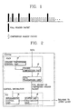
- Figure 1 is a diagram showing a transmission intervals for transmitting full-header information in accordance with the CSS method.
- the transmission intervals for the full-header packet increase exponentially, and the number of compressed header packets transmitted between neighboring full-header packets (i.e., within each interval) is increased by 1, 2, 4, 8, ....
- the transmission interval is not infinitely increased but maintained at the same interval when it reaches a transmission interval threshold value, which is usually set by 256.
- the full-headers transmitted by the CSS method have the same CID (context identifier) value and generation number. That is, the full-header packet is transmitted in an exponential period for a packet stream with the same CID and generation value.
- the header size of the packet can be considerably reduced.
- the header of the packet is too big to be neglected compared with the payload size (a data portion of the packet), the header needs to be compressed.
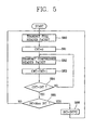
- FIG. 2 is a block diagram of a packet transmission system of the related art which uses a header compression technique.
- the system includes a header compression unit 10, provided in the PDCP layer, which compresses a header of data received from an upper layer under control of a header compression control unit 12.
- the full-header packet or the compressed header packet converted by the header compression unit 10 is delivered to the RLC layer through a data transmission unit 14.
- a buffer and transmission unit 16 of the RLC layer stores the full-header packet or the compressed header packet received from the data transmission unit 14 of the PDCP and/or transmits it to a receiving party.
- a transmitting party first transmits a full-header packet for a packet stream to construct a context at a receiving party.
- One or more compressed headers are then transmitted indicating differences between successive packets.
- the receiving party fails to restore subsequently received compressed headers.
- the following compressed headers cannot be restored, just as in the case where the full-header packet is lost. Since the damaged context can be recovered only by receiving a new full-header of a corresponding context, the receiving party transmits a context- state packet requesting transmission of a new full-header of the corresponding context from the transmitting party.
- Figure 3 shows a structure of a context-state packet in accordance with the related art.
- This packet includes a plurality of CID fields, each of which signifies one damaged context, that is, one damaged packet stream.
- Such a context-state packet is not used whenever one context is damaged, but is transmitted to the transmitting party when more than a predetermined number of contexts are damaged.
- transmission of the context-state packet itself from the receiving party to the transmitting party wastes radio resources, so that its frequency of use is limited in RFC 2507.
- Figure 4 shows a structure of a compressed header used in a UDP/IP protocol.
- the generation value of corresponding header information as well as the CID value is used to discriminate packet streams.
- the compressed header only contains the CID field, the generation field, and the checksum field and as a result has a total length of about 4-5 octets.
- a full-header packet is transmitted at the first packet of a packet stream.
- the following packets are transmitted with compressed header containing the variance from previously transmitted headers of a packet stream.
- the context of the packet stream is continuously updated with the compressed header in the reference of previously received packet headers.
- a full-header packet is transmitted at the first packet of a packet streae first packet of a packet streansmitted with compressed header containing the variance from previously transmitted full header of the packet stream.
- the context of the packet stream is continuously updated with the compressed header in the reference of previously received full header.
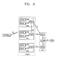
- FIG. 5 is a flow chart of a related art method for transmitting a full-header packet and a compressed header packet according to the CSS method.
- an INT (Interval) value indicates the number of compressed header packets that can be transmitted between two consecutively transmitted full-header packets
- a CNT (Count) value indicates the number of transmitted compressed header packets.
- a compressed header packet is transmitted, and when the CNT value and the INT value become the same, the full-header packet is transmitted instead of the compressed header packet.
- the INT value is updated at the time when the full-header is to be transmitted.
- the INT value reaches a MaxINT, which corresponds to a transmission interval threshold value, the INT value is no longer increased and the MaxINT is maintained.
- the process is terminated when all data in a packet stream are transmitted or when the full-header information is changed.
- the minimum number (INT) of compressed header packets that can be transmitted between the full-header packets is set to an initial value of '1'.
- Transmitting full-header packets using the CSS method of the related art is advantageous in at least two respects.
- the CSS method of the related art has a number of drawbacks. For example, since the full-header is much larger than the compressed header, repeated transmission of a considerable number of full-header packets within a same data stream substantially degrades transmission efficiency. This is especially true if the full-header packet is successfully transmitted at the initial stage. Under these circumstances, the related art method will continue to intermittently transmit full-header packets in the data system even though the initial full-header packet was successfully transmitted. As will become more apparent below, the Inventors of the present invention have determined that every full-header packet transmitted after an initial full-header packet has been successfully received may be considered to be an unnecessarily transmitted one.
- the Compressed TCP header compression technique following the TCP/IP Header Compression Algorithm of the related art also has a number of drawbacks.
- the context of a packet of compressed header is recovered in the reference of the full-header directly or indirectly. If, one of the headers of a packet in a stream is not received successfully or the full-header is not received successfully, several packets following that packet could not be recovered for a time being. That is, the transmission of packet data using the Compressed TCP header compression technique, if a full-header packet or a compressed header packet is lost, it takes a large amount of time to restore a corresponding context by the receiving party. Moreover, the transmitting party is not aware that the corresponding context has been damaged. Thus, the following compressed header packets are uselessly transmitted, which results in wasting radio resources. If the receiver transmits the request of sending a full-header packet to the transmitter immediately, the traffic load for the request might be a burden to the radio channel.
- An object of the invention is to solve at least the above problems and/or disadvantages and to provide at least the advantages described hereinafter.
- It is another object of the present invention is to achieve the aforementioned object by substantially increasing the efficiency of recovering the context of the header information and the packets transmitted in the system while at the same time decreasing the request of sending a full-header packet to the transmitter in any given data stream compared with other proposed systems.
- It is another object of the present invention is to achieve the aforementioned object by substantially decreasing the number full-header packets transmitted in the system while at the same time increasing the number of compressed header packets in any given data stream compared with other proposed systems.
- It is another object of the present invention is to provide a packet data transmitting system method which improves a transmission efficiency and decompression efficiency of a packet when a Compressed TCP compression technique is used in a UMTS system.
- It is another object of the present invention is to provide a packet data transmitting method in which, when a full-header packet of a specific packet stream is repeatedly transmitted periodically or non-periodically, transmission of the full-header packet is controlled to thereby increase a transmission efficiency.
- a packet data transmitting method of a communication system in which, with respect to one packet stream, a header compression layer of a transmitting party determines the transmission of a full-header packet with a full-header or a compressed header packet with a compressed header through a data link layer in the reference of the transmission status of the previous data packet in the data link layer.
- transmitting party including the steps of: receiving a packet data stream from upper layer; transmitting a full-header packet having full-header information of the packet data stream through a lower layer; transmitting a compressed header packet having a compressed header holding a portion of the full-header information through the lower layer; detecting the packet has been received by the receiving party with the report of the lower layer; and transmitting a packet to be transmitted as a full-header packet if it is detected that the packet has not been received.
- the detecting step includes steps of: detecting whether a data link layer detects a packet transmission failure; and receiving the detected transmission failure information from the data link layer.
- the transmission failure information contains ID information and/or transmission failure indicating information of the corresponding packet.
- the predetermined compression method is that a context is updated by the header of present packet in the reference of the previous packet header successively updated from the full-header.
- the compression method updated with the header of present packet in the reference of the previous packet header successively updated from the full-header is a Compressed TCP technique.
- the predetermined compression method is that a context is updated by the header of present packet in the reference of the previous full-header.
- the compression method that a context is updated with the full-header packet is a Compressed TCP nondelta technique.
- the header compression layer is a packet data convergence protocol (PDCP) layer and the data link layer is a radio link control (RLC) layer.
- PDCP packet data convergence protocol
- RLC radio link control
- an upper layer at the control plane of the RLC layer is an RRC layer which manages a radio resource, and the RRC layer sets a radio bearer such that information of an SDU discarded from the RLC is provided to the PDCP layer.
- the PDCP layer when the PDCP layer delivers a PDCP PDU to the RLC layer, the PDCP layer instructs the RLC layer to inform the PDCP layer about a transmission failure result on the corresponding PDU.
- the PDCP layer when the PDCP layer delivers the PDCP PDU to the RLC layer, the PDCP layer transmits a transmission failure report indicator together with the corresponding PDU.
- a packet data transmitting method of a communication system in which, with respect to one packet stream, a header compression layer of a transmitting party transmits a full-header packet with a full-header or a compressed header packet with a compressed header through a data link layer and a header compression layer of a receiving party recovers compressed header information of the compressed header packet by using full-header information of the full-header packet, including the steps of: receiving a packet data stream using an Internet protocol; transmitting a full-header packet having full-header information of the packet data stream; transmitting a compressed header packet having a compressed header holding a portion of the full-header information; detecting whether the packet has been received by the receiving party; and transmitting a packet to be transmitted the very next as a full-header packet if it is detected that the packet has not been received.
- the detecting step includes steps of: detecting whether a data link layer detects a packet transmission failure; and delivering the detected transmission failure information to the header compression layer.
- the transmission failure information contains ID information and/or transmission failure indicating information of the corresponding packet.
- the predetermined compression method is that a context is updated by the header of present packet in the reference of the previous packet header successively updated from the full-header.
- the compression method updated with the header of present packet in the reference of the previous packet header successively updated from the full-header is a Compressed TCP technique.
- the predetermined compression method is that a context is updated by the header of present packet in the reference of the previous full-header.
- the compression method that a context is updated with the full-header packet is a Compressed TCP nondelta technique.
- the packet data transmitting method of the present invention preferably, further includes a step of delivering a fresh full-header packet to the transmitting party of the data link layer if the transmission failure information is received from the data link layer.
- the header compression layer compresses a following first packet using the same CID with the transmission-failed packet to a full-header packet and transmits it.
- the header compression layer is a packet data convergence protocol (PDCP) layer and the data link layer is a radio link control (RLC) layer.
- PDCP packet data convergence protocol
- RLC radio link control
- an upper layer at the control plane of the RLC layer is an RRC layer which manages a radio resource, and the RRC layer sets a radio bearer such that information of an SDU discarded from the RLC is provided to the PDCP layer.
- the PDCP layer when the PDCP layer delivers a PDCP PDU to the RLC layer, the PDCP layer instructs the RLC layer to inform the PDCP layer about a transmission failure result on the corresponding PDU.
- the PDCP layer when the PDCP layer delivers the PDCP PDU to the RLC layer, the PDCP layer transmits a transmission failure report indicator together with the corresponding PDU.
- the present invention also provides a packet data transmitting method in a header compression layer that transmits a full-header packet or a compressed header packet through a data link layer with respect to one packet stream so that a receiving party can restore compressed header information of the compressed header packet by using full-header information of the full-header packet; including the steps of: delivering the full-header packet or the compressed header packet to the data link layer; detecting a transmission result of a packet by the data link layer; and sending a following packet as a full-header packet and transmitting it when transmission failure information is delivered from the data link layer over more than one packet.
- the present invention also provides a packet data transmitting apparatus which includes a header compression unit provided in a header compression layer and compressing a header of a data received from an upper layer to transform it to a full-header packet or to a compressed header packet; a header compression control unit for controlling header compression of the header compression unit according to transmission failure information; a data transmission unit for delivering the transformed full-header packet or the compressed header packet to a data link layer; a buffer and transmission unit provided in the data link layer and transmitting a packet transmitted from the data transmission unit of the header compression layer to a receiving party; and a transmission failure discriminating unit for discriminating a transmission failed-packet of packets transmitted to the receiving party and delivering transmission failure information to the header compression control unit.
- the transmission failure information contains ID information of a corresponding packet or/and a transmission failure indicator.
- the header compression control unit controls the header compression unit to compress a following first packet using the same CID as a CID of the transmission-failed packet as a full-header packet if it receives transmission failure information from the transmission failure discriminating unit.
- the header compression layer is a packet data convergence protocol (PDCP) layer and the data link layer is a radio link control (RLC) layer.
- PDCP packet data convergence protocol
- RLC radio link control
- the present invention also provides, a packet data transmitting method of a communication system in which, with respect to one packet stream, a header compression layer of a transmitting party determines the transmission of a full-header packet with a full-header or a compressed header packet with a compressed header through a data link layer in the reference of the transmission success of the previous full-header packet in the data link layer.
- transmitting party including the steps of: receiving a packet data stream from upper layer; transmitting a full-header packet having full-header information of the packet data stream through a lower layer; transmitting a compressed header packet having a compressed header holding a portion of the full-header information through the lower layer; detecting the packet has been received by the receiving party with the report of the lower layer; and transmitting a packet to be transmitted as a compressed-header packet if it is detected that the packet has been received.
- a transmitting party transmits a full-header packet or a compressed header packet and a receiving party recovers compressed header information of the compressed header packet by using full-header information of the full-header packet, including the steps of: receiving a packet data stream using an Internet protocol; transmitting a full-header packet having full-header information of the packet data stream; detecting whether the receiving party has received the packet; and transmitting packets in the same stream which is transmitted next as compressed header packets when it is detected that the packet has been received.
- the header compression layer does not transmit the full-header packet any more and transmits only the compressed header packet.
- the full-header packet is transmitted by using a compression slow start technique.
- the header compression handling layer receives information on a failure of transmitting of the full-header packet over a specific packet stream from a data link layer, and if no full-header packet has been successfully transmitted previously, the header compression handling layer immediately transmits additionally a full-header packet for a corresponding packet stream regardless of a transmission period of the full-header packet.
- the full-header packet is transmitted in a pre-set transmission period of the full-header packet after the additional transmission of the full-header packet.
- the transmission result is packet ID information and transmission result information.
- the header compression layer delivers the full-header packet to the data link layer, a lower layer, it transmits the full-header packet and a full-header packet indicator indicating the full-header packet together.
- the header compression layer when the header compression layer receives information that the full-header packet has been successfully transmitted from the data link layer, the header compression layer does not perform a periodically or non-periodically repeated transmission of the full-header packet with respect to the corresponding packet stream but transmits only the compressed header packet.
- the present invention also provides a packet data transmitting method of a communication system in which a header compression layer repeatedly transmits a full-header packet over a specific bit stream to a receiving party through a data link layer periodically or non-periodically, including the steps of: transmitting a full-header packet or a compressed header packet; detecting a transmission result of the compressed header packet; and transmitting only a compressed header, not the full-header packet, when at least one full-header packet is successfully transmitted with respect to one packet stream.
- the full-header packet is transmitted by using a compression slow start technique.
- the packet data transmitting method of the present invention further includes a step of additionally transmitting a full-header packet with respect to a corresponding packet stream regardless of a transmission period of the full-header packet if transmission of a full-header packet with respect to a specific packet stream is failed and no full-header packet has been successfully transmitted previously.
- the transmission result is ID information of a packet and transmission result information.
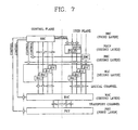
- FIG. 6 is a drawing showing a network structure of a packet-switching domain proposed by the TSG-RAN and the TSG-CN.
- the UTRAN includes a plurality of radio network subsystems (RNSs), each of which includes a plurality of nodes B connected to one radio network controller (RNC).
- RNSs radio network subsystems
- RNC radio network controller
- the core network has a different structure according to an adopted switching mode (the packet-switching network or the circuit-switching network).
- the CN preferably includes a plurality of Serving GPRS support nodes (SGSNs) and one gateway GPRS support node (GGSN).
- SGSNs Serving GPRS support nodes
- GGSN gateway GPRS support node
- Each node B serves as a connection point for establishing a connection between user equipment (UE) (generally called a mobile station or a terminal) and the UTRAN.
- UE user equipment
- the RNC assigns a radio resource to each UE and manages the radio resource.
- the RNC is classified into one of two types.
- One type of RNC known as a control RNC (CRNC)
- CRNC control RNC
- a second type of RNC known as a serving RNC (SRNC)
- SRNC serving RNC
- An RNC where the SRNC of the UE is positioned is called an SRNC, when viewed from a specific UE.
- the SGSNs route information transmitted from the UTRAN to the CN, and the GGSN serves as a gateway to pass information from the UTRAN to different CNs, if a destination of the information is a network different from the current CN.
- Data interfaces of each part have different names as follows.
- An interface between the UE and the nodes B is called 'Uu'
- an interface between the nodes B and an associated RNC is called 'lub'
- an interface between the RNCs is called 'lur'
- an interface between the RNCs and the SGSNs is called 'lu'
- an interface between the SGSNs and the GGSN or between the SGSNs is called 'Gn'.
- the packet domain network is a backbone network of a packet-switching domain which supports connection between different networks in a packet service area.
- Figure 6 shows an example of a network structure, in which the interface 'lur' may optionally exist between RNCs of a different SGSN. Also, the interface 'Gn' may optionally exist between the SGSNs.
- Figures 7 and 8 show that the network structure of Figure 6 has a hierarchical structure.
- a detailed hierarchy of the UTRAN or the UE is shown for supporting an interface 'Uu', which is a radio interface.
- the user plane (U-plane) is a region to which traffic information of a user such as a voice or IP packet is transmitted
- the control plane (C-plane) is a region to which control information such as maintenance and management of an interface or call is transmitted.
- the U-plane includes a physical layer (L1) serving as a first layer, a packet data convergence protocol (PDCP) layer, a radio link control (RLC) layer, a medium access control (MAC) layer, and a broadcast/multicast (BMC) layer serving as a second layer (data link layer) of the 7 layers defined by OSI (Open Systems Interconnection) model.
- L1 physical layer
- PDCP packet data convergence protocol
- RLC radio link control
- MAC medium access control
- BMC broadcast/multicast
- the C-plane includes a radio resource control (RRC) layer, an RLC layer, a MAC layer, and an L1 layer.
- RRC radio resource control
- the L1 layer (the physical layer) provides an information transmission service to an upper layer using diverse radio access techniques.
- the L1 layer is connected to the MAC layer through a transport channel, and data between the MAC layer and the L1 layer is exchanged through the transport channel.
- the transport channel is classified into one of two types, namely a dedicated transport channel and a common transport channel, depending on whether one dedicated terminal is used for the channel or the channel is shared by a plurality of terminals.
- the MAC layer provides a MAC parameter re-allocation service for allocating and re-allocating the radio resource.
- the MAC layer is connected to the RLC layer through a logical channel, and diverse logical channels are provided according to types of transmitted information. In general, when information is transmitted on the C-plane a control channel is used, and when information is transmitted on the U-plane, a traffic channel is used.
- the RLC layer performs the functions of setting up or releasing a radio link, segmenting and re-assembling the RLC service data units (SDU) coming down from an upper layer, and handling re-transmission of RLC PDUs lost during transmission.
- SDU RLC service data units
- RLC SDUs The size of RLC SDUs is controlled in the RLC layer. Then, headers are attached in order to transform the SDUs into protocol data units (PDUs) for transmission to the MAC layer.
- PDUs protocol data units
- the RLC layer operates in three modes, namely a transparent mode, an unacknowledged mode, and an acknowledged mode, according to a processing method of the RLC SDU.
- An RLC buffer is included in the RLC layer to store the RLC SDU or the RLC PDU.
- the PDCP layer is an upper layer of the RLC layer which allows data transmitted through an IP network protocol, such as an IPv4 or an IPv6, to be effectively transmitted in the RLC layer.
- the PDCP layer also reduces header information which is unnecessary for a wireless network but which may be used for a wired network, thereby ensuring that the data can be effectively transmitted. This function, called header compression, may be used to reduce an amount of header information used, for example, in TCP/IP communications.
- the PDCP layer and the BMC layer are shown positioned on the user plane since they only transmit user data.
- the RLC layer may belong to the user plane or the control plane according to a layer connected to an upper side thereof. That is, when the RLC layer receives data from the RRC layer, it belongs to the control plane, while in other cases the RLC layer belongs to the user plane.
- the transmission service of user data provided from the user plane to the upper layer by the L2 layer is defined as a radio bearer (RB), and a transmission service of control information provided from the control plane to the upper layer by the L2 layer is defined as a signaling radio bearer (SRB).
- RB radio bearer
- SRB signaling radio bearer
- the RLC layer and PDCP layer may each include a plurality of entities. This is because one UE may have several RBs and, in general, one RLC entity and one PDCP entity are used for one RB.
- the entities of the RLC layer and the PDCP layer can perform independent functions in each layer.
- the BMC layer transmits a message from a cell broadcast center (CBC) through a radio interface.
- a main function of the BMC is to schedule a cell broadcast message transmitted to the UE and to transmit it through an RLC layer operating in an unacknowledged mode.
- the RRC layer positioned at the lowermost of the third layer (L3), is defined only in the control plane. It functions to broadcast system information to every UE positioned in an arbitrary area.
- the RRC layer also processes a control plane signal for a control signal exchanged in the third layer, and performs a function of setting up, maintaining and releasing a radio resource between the UE and UTRAN.
- the RRC layer sets up, re-constructs, and releases an RB and performs a function of allocating, re-arranging, and releasing a radio resource required for establishing a radio resource connection.
- setting up an RB includes a process of determining a protocol layer and channel characteristics required for providing a predetermined service in a radio area, as well as setting up each specific parameter and an operation method.
- Services provided to the UE may generally be classified into circuit-switching services and packet-switching services.
- a voice call service is included, for example, in the circuit-switching service and a Web-browsing service through an Internet connection may be included in a packet-switching service.
- the circuit-switching service is connected to the UTRAN through the MSC of the core network, and the packet-switching service is provided through the SGSN of the core network.
- an access point with the core network to which the UTRAN is connected differs depending on the type of service provided.
- Figure 8 is a diagram showing an example of a protocol structure of the user plane which may be used to provide a packet-switching service in the UMTS network.
- the SGSN supports the packet-switching service directed to the UTRAN and handles mobility management functions such as routing-area updating, position-information registration or calling, and security-related controlling.
- the GGSN supports a connection to a different packet-switching network such as an Internet network. A process of transmitting a packet-switching service from an external packet-switching network to a terminal will now be described.
- packets related to an application program reach the GGSN in the form of IP packets.
- the GGSN Upon confirming addresses of the IP packet, the GGSN transmits the packets to the UTRAN through the SGSN.
- a GTP-U used for transmission of the IP packet capsulizes the user data between the UTRAN and the SGSN or between the SGSN and the GGSN and tunnels it. That is, the GTP-U receives a user data packet from the external packet network, detects a destination address of the packet, and transmits it to the next destination according to a set path.
- a user datagram protocol (UDP)/IP protocol widely used for packet transmission in a wired network is positioned in the lower layer of the GTP-U protocol and carries the GTP-U packet.
- the RLC layer suitably segments or concatenates the RLC SDUs coming down from the upper layer and fits them into the form of an RLC PDU, thereby constructing the RLC PDU. If the RLC SDU is larger than the RLC PDU, the RLC SDU can be segmented to construct several RLC PDUs. On the other hand, if the RLC SDU is smaller than the RLC PDU, several RLC SDU can be grouped together to construct one RLC PDU. The thusly constructed RLC PDUs are multiplexed with the RLC PDUs of other UEs in the MAC layer and transmitted to the physical layer.
- the PDCP PDU is delivered through the MAC and RLC layers to the PDCP layer, and the PDCP layer of the UE restores the compressed header information to recover an original IP header.
- the resulting IP packet is then delivered to the IP layer.
- the header compression technique that the PDCP layer performs at the UE and UTRAN will now be described.
- the reason why the header should be compressed is because the header size of the IP packet is not so small as to be neglected compared to the payload size of the packet.
- header information of an IP is added to each packet to allow the packet to be routed in the IP network.
- IPv4 24 octet header information is attached, and in the case of IPv6, 40 octet header information is attached.
- 24 octet and 8 octet header information are additionally required.
- at least 64 octet header information is required per packet, while in case of transmitting a packet using the UDP/IPv6, at least 48 octet header information is required per packet.
- Header compression techniques perform compression based on the realization that packets belonging to the same packet stream have almost the same header information.
- a packet stream signifies continuous packets having similar header information and, in general, packets used to provide a specific service may be considered as belonging to the same packet stream. For example, in the case of transmitting packets for TCP/IP, packets transmitted with the same address and port number are considered to belong to the same packet stream.
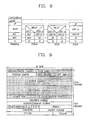
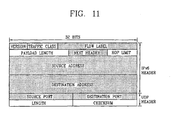
- FIG. 9 shows a TCP/IPv6 header field provided to understand the principle and compression rate of a header compression technique. Initially, it is noted that as described above with respect to the discussion of packet stream, since address fields of the IPv6 and port numbers of the TCP header belong to the same packet stream, they may be considered to be constant.
- a version field indicates use of an Ipv6 header and the next header (NH) field indicates that header information coming after the IPv6 header is a TCP header. As a result, the two can be considered the same with respect to the corresponding packet stream.
- a traffic class field indicates a priority of the corresponding packet, and a flow label (FL) field controls a packet according to the priority.
- FL flow label
- the traffic class field ahead of the FL field will not change.
- the traffic class field value may be changed.
- packets having a value of a different traffic class field may be defined as belonging to a different packet stream, values of the traffic class field and the FL field are considered unchanged with respect to one packet stream.
- a hop limit (HL) field is reduced by '1' whenever a router is passed in a network. If the HL field value becomes '0', a corresponding packet is discarded. In general, since packets are transmitted through the same path in a network, the HL field value is also considered almost constant for a specific packet stream.
- An offset field indicates a start point of the TCP data, which is constant.
- the header fields containing information which is not changed mostly correspond to the fields of Figure 9 which are shaded.
- the PDCP layer may use an RFC 2507 and RFC 3095-based header compression technique.
- RFC 2507 header compression technique a different compression technique can be used depending on whether a protocol positioned above the IP layer is TCP or Non-TCP. If the protocol above the IP layer does not use TCP such as the UDP/IP protocol, a 'compression Non-TCP' method may be used.
- the protocol above the IP layer is TCP, it is divided into a 'compressed TCP' and a 'compressed TCP nondelta' according to the way the variable header field is transmitted.
- the compressed TCP technique is a method of transmitting a difference value between consecutive packets, rather than sending an overall field value. This is performed based on the concept that a small difference exists between varying header field values.
- the 'compressed TCP nondelta is a method of transmitting a varying header field as it is.
- header compression may be performed by first transmitting a full-header containing every field of a non-compressed header.
- the portion which is not changed in a specific packet stream of the full-header, such as shown by the shaded portions in Figure 4 is used to recover a compressed header to be transmitted thereafter.
- the information required for recovering the compressed header is defined a context of a corresponding packet stream, and this context serves as reference information in recovering the compressed header to a normal header.
- a packet containing the full-header required for updating or generating a context may be defined as a full-header packet, and a packet in which header information is compressed and transmitted may be defined as a compressed header packet.
- a full-header packet is much larger than the general compressed header packet, and a packet stream is preferably constructed such that the field is not frequently changed in one packet stream.
- a header compression technique used to compress a header using the 'compressed TCP' or the 'compressed TCP nondelta' such as TCP/IP will now be described.
- a header technique has been proposed which transmits a full-header packet as a first packet in a data stream.
- an identifier indicating a context for each packet stream may be used to distinguish these streams.
- An identifier of this type is referred to as a context identifier (CID).
- the CID value has a length of 8 bits for a TCP packet, and when the compressed header or the full-header is transmitted the CID value should also be transmitted.
- the transmitted full-header information is stored in the receiving party according to the CID value, and when the packet arrives the receiving party reads the full-header information based on the CID value to recover original header information.
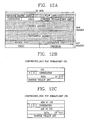
- FIG 10A shows a structure of a full-header transmitted in adopting the header compression technique for the TCP/IPv6.
- the full-header is the same for 'Compressed TCP' and 'Compressed TCP nondelta'.
- the original TCP/IPv6 header field does not include a CID field, it is not possible to insert the CID value.
- a suitable field should be found into which the CID value may be inserted. Since information of the existing 'payload length' field is information that can be known from a lower layer, the corresponding field is not necessarily used. Therefore, the CID may be inserted into the 'payload length' field and transmitted.
- Figures 10B and 10C illustrates the compressed TCP format and the compressed TCP nondelta format, respectively, in accordance with a preferred embodiment of the present invention.
- a compressed header formed by the compressed TCP technique and transmitted using TCP/IPv6 is constructed in accordance with the non-shaded portions of the header of Figure 10A .
- a CID field has a fixed value
- a checksum field has a variable value
- remaining fields have a difference value from the previous compressed header.
- the size of the compressed header is usually 4-7 octets.
- the compressed header is constructed in accordance with the non-shaded portions of the header of Figure 10A , which is just the same as the compressed TCP technique.
- a CID field has a fixed value and the remaining fields have variable values. Since all the fields other than the CID field have variable values and the variable values usually take more bits than the difference values, the size of a Compressed TCP nondelta header is larger than that of a Compressed TCP header.
- the size of the compressed header is usually 17 octets.
- a protocol which does not use TCP such as the UDP/IP protocol, compresses a header using a 'Compressed Non-TCP' method similar to the case of TCP/IP.
- a process of transmitting a full-header packet as a first packet is necessary and including a CID for identifying each packet stream is also necessary.
- the CID value which usually has an 8-bit length or a 16-bit length, should be transmitted together with a compressed header or the full-header.
- a generation field indicating generation of header information is additionally used.
- the generation field indicates how old header information of a packet is and it is always transmitted together with the CID value.
- Figure 12A shows a structure of a full-header transmitted in accordance with a header compression technique used for a UDP/IPv6 packet.
- the CID and the generation values are inserted into the existing 'payload length' field or 'length' field and then transmitted.
- an 8-bit CID value is used, only CID(1) may be used.
- CID(2) may be used and a portion of the payload length field is used for the generation value.
- Figures 12B and 12C illustrate a compressed non-TCP format of 8 bit CID and a compressed non-TCP format of 16 bit CID, respectively, in accordance with a preferred embodiment of the present invention.
- the compressed header transmitted using the header compression technique for UDP/IPv6 is constructed in accordance with the non-shaded portions of the header shown in Figure 12A .
- the size of this header is usually 4-5 octets.
- the CID field and the generation field have a fixed value while the checksum field has a variable value.
- the present invention is a system and method for controlling the transmission of packets in a communications system in a manner which is faster and more efficient than other proposed systems.
- the invention achieves this improved performance by employing a packet header compression scheme which determines the transmission of a packet with one of full-header or compressed header according to the report of a lower layer, preferably, without any request from the receiver.
- the determination is done in PDCP layer, and the lower layer is RLC layer.
- the invention permits transmitting a full-header packet even if the receiver did not request.
- the full-header packet is preferably the first packet transmitted in the stream, but if desired the full-header packet may be transmitted after the first packet.
- the remaining packets in the stream are preferably compressed header packets.
- the invention permits transmitting a full-header packet after the first full-header packet.
- the compressed headers are transformed into full-headers based on the full-header information in the newly transmitted full-header packet, though the receiver failed to establish the context of header information of a packet stream with the first full-header packet.
- the invention achieves the improved performance by employing a packet compression scheme which minimizes the number of packets transmitted with full-header information in any given data stream. This ensures that almost all packets in the stream are transmitted with compressed header information, thereby improving transmission efficiency and data rates.
- the invention permits transmitting an entire data stream with only one full-header packet and the remaining packets in the stream are transmitted with compressed headers.
- the compressed packets are transformed into full-header packets based on information in the single full-header packet.
- the invention is ideally suited for use in a mobile radio communication system such as UMTS system which transmits packets according to a protocol which includes a header compression layer and a data link layer.
- the header compression layer generates and sends compressed- and full-header packets to the data link layer for transmission.
- one of the novel features is to determine one of full-header or compressed header according to the report of a lower layer, and preferably, regardless of any request from the receiver. The determination is done in PDCP, and the lower layer is the RLC of the transmitter.
- the header compression layer controls which packets to compress based on feedback information from the data link layer which indicates whether a previously transmitted full-header packet has been discarded (it means that the transmission was failed). If so, the next packet in the stream may be transmitted as full-header packets. If not, the receiver may fail to establish the context of header information of a packet stream with the first full-header packet or the successive packet with compressed header and may not recover the header information by the compressed-header packet. Even though the receiver might establish the context of header information of a packet stream with the first full-header packet, the header compression layer of the transmitter sends a full-header packet whenever the lower layer reports that it discarded a packet. Through this feedback information of the lower layer, the invention is therefore able to minimize the number of request of full-header packets from the receiver.
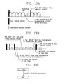
- FIG. 13A graphically illustrates this feature of the preferred embodiment relative to the compressed and full header packet transmission. As shown therein, if the RLC layer (e.g., of the transmitter) reports that the transmission of a packet has failed, the PDCP layer (e.g., of the transmitter) sends a full header packet after a prescribed reporting time.
- the RLC layer e.g., of the transmitter
- the PDCP layer e.g., of the transmitter
- the header compression layer controls which packets to compress based on feedback information from the data link layer which indicates whether a previously transmitted full-header packet has been successfully received. If so, the remaining packets in the stream may be transmitted as compressed-header packets. If not, one or more full-header packets are intermittently transmitted until one is successfully received. The remaining packets are then transmitted as compressed-header packets. Through this feedback information of the lower layer, the invention is therefore able to minimize the number of full-header packets transmitted in any given data stream.
- Figure 13B graphically illustrates this feature of the preferred embodiment relative to the compressed and full header packet transmission for compressed non-TCP for CSS.
- the RLC layer in this case, of the transmitter
- the PDCP layer in this case, of the transmitter
- the PDCP does not send a full header packet at the prescribed intervals of 1, 2, 4, 8, etc, after receiving the RLC report.
- the PDCP sends a full header packet after receiving the RLC report.
- Figure 13C illustrates the parameters delivered between the PDCP and the RLC for implementing the reporting instruction.
- the PDCP delivers to the RLC the packet, the packet identifier and parameter DiscardReq which indicates whether the transmitting RLC entity needs to inform the upper layers of the discarded RLC SDU. If required, the transmitting RLC entity notifies upper layers when the SDU is discarded.
- a parameter Status indicates whether an RLC SDU is sucessfully transmitted or discarded.
- the present invention is especially well suited for use in the packet-switching domain proposed by the TSG-RAN and TSG-CN. Detailed embodiments of the invention will now be discussed.
- FIG 14 is a block diagram of a packet transmission system in accordance with one embodiment of the present invention includes a PDCP portion and an RLC portion.
- the RLC portion includes a transmission failure discriminating unit 20, transmitting unit 16, and transmission control unit 18.
- the transmission failure discriminating unit is preferably provided in the RLC layer and performs two functions. The first function is discriminating a transmission-failed packet data among packet data transmitted through the buffer. The second function is sending feedback information to a header composition control unit 12 along a feedback path 200.
- the transmission failure discriminating unit also sends information to an open protocol layer indicating that a transmission failure of packet data has occurred. Remaining elements in the system may be similar to those in the related art packet transmission system illustrated in Figure 2 .
- data transformed into a full-header packet or a compressed header packet in a header compressing unit 10 of the PDCP layer is delivered to the RLC layer through a data transmission unit 14.
- the RLC layer stores the received packet data in a buffer 16 and/or transmits it to a receiving party through a transmitting unit 16 based on control information from a transmission control unit 18.
- the transmission failure discriminating unit 20 discriminates whether transmission of a packet from the RLC layer to the receiving party has failed and delivers transmission failure information to a header compression control unit 12 in the PDCP layer along path 200.
- the transmission failure information preferably includes ID information of a corresponding packet and/or a transmission failure indicator.
- the PDCP layer controls header compression unit 10 based on the transmission failure information delivered from the RLC layer. Specifically, if the header compression control unit in the PDCP layer receives a transmission failure indicator from unit 20 indicating that a transmission failure has occurred from the RLC layer, control unit 12 controls the header compressing unit 10 to compress a following packet (and preferably the first packet to follow) using the same CID as a CID of the transmission-failed packet as a full-header packet and delivers it to the RLC layer.
- This aspect of the invention may be modified in a number of ways.
- the RLC layer In the case of using a header compression technique which updates a context by only using a full-header packet, when the full-header packet, among packets delivered from the PDCP layer to the RLC layer, is not successfully transmitted to the receiving party, the RLC layer provides ID information and transmission failure information of the corresponding packet to the PDCP layer.
- the header compression layer (PDCP layer) of the transmitting party transmits a new full-header packet of the corresponding context to the receiving party immediately when it receives the transmission failure information on the corresponding packet from the lower data link (RLC) layer. Accordingly, the receiving party can prevent additional loss of packets and recover the context quickly.
- PDCP layer header compression layer
- the transmission result on an RLC SDU transmitted from the RLC layer is delivered to the PDCP layer, so that the PDCP layer can effectively control, periodically or non-periodically, repeated transmission of the full-header packet.
- the RLC layer performs the additional function of informing a transmission result of the PDCP PDU (e.g., RLC SDU), coming down from the PDCP layer.
- the RLC layer When operated in transparent mode, the RLC layer transmits an RLC SDU from the PDCP layer as is, i.e., without adding header information to it. Whether or not a segmentation function should be used can be determined according to the setup of a radio bearer, but even in the case where an RLC SDU is segmented no header information is added.
- the RLC layer When operated in unacknowledged mode, the RLC layer constructs the RLC PDU using a segmentation and concatenation function for the RLC SDU, adds header information thereto, and transmits it to the receiving party.
- the receiving party does not transmit any information regarding receipt of the RLC PDU to the transmitting party (RLC layer).
- the RLC layer When operated in acknowledged mode, the RLC layer segments or concatenates RLC SDUs to form PDUs of a pre-defined size, adds RLC header information containing a sequence number, and stores the result in the RLC buffer.
- acknowledged mode bi-directional communication between RLCs is possible. As a result, re-transmission of a packet lost during transmission may be performed.
- the RLC of the transmitting party transmits RLC PDUs in an order determined by transmission sequence numbers.
- the RLC layer of the receiving party recognizes which RLC PDUs have not been successfully transmitted by observing the sequence numbers of the RLC PDUs which are successfully received.
- the receiving party may then generate a status PDU indicating which PDUs were and were not successfully transmitted. PDUs which were not successfully received may be designated with negative acknowledgment information.
- the status PDU is transmitted to the transmitting party, and upon receiving the status PDU the transmitting party may re-transmit the unsuccessfully transmitted RLC PDUs, i.e., the ones designated with a negative acknowledgment.
- the RLC layer of the transmitting party recognizes a transmission result of a specific RLC PDU based on the acknowledgment/non-acknowledgment information included in the status PDUs transmitted from the RLC layer of the receiving party.
- the RLC layer of the transmitting party can recognize a corresponding relationship between an RLC PDU and an RLC SDU, the RLC layer of the present invention can easily recognize a transmission result for a specific RLC SDU.
- the RLC layer may inform the PDCP layer of a transmission result of a specific RLC SDU, and the PDCP layer will as a result detect the transmission result of the full-header packet, thereby ensuring that the full-header is more effectively transmitted compared with related art methods.
- the RLC layer of the transmitting party informs the PDCP layer of the transmitting party of the identification number and transmission result of the corresponding RLC SDU.
- the transmission result may be transmission success information or transmission failure information. Transmission success information is sent to the PDCP layer when the RLC layer is informed, for example, based on a received status PDU that a specific RLC SDU was successfully transmitted.
- Transmission failure information is sent to the PDCP layer, for example, based on a received status PDU indicating that a specific SDU was not successfully transmitted and/or when the RLC layer discards one or more RLC SDUs that are not transmitted for a long time.
- the RRC layer which is an upper layer relative to the PDCP layer which handles header compression, sets a radio bearer so that the RLC layer provides the PDCP layer with information on the RLC SDU discarded from the RLC.
- the PDCP layer delivers a PDCP PDU to the RLC layer, it instructs the RLC layer to inform the PDCP layer about the transmission failure result with respect to the corresponding PDCP PDU.
- the RLC layer vis-a-vis transmission control unit 18 delivers a transmission result report indicator with the corresponding PDU, so that the RLC layer provides the PDCP layer with the information regarding discarding of the corresponding SDU in its occurrence.
- the transmission result of a full-header packet may be considered more important than the transmission result of a compressed header packet.
- the RLC layer informs the PDCP layer of only the periodically or non-periodically repeated transmission result of the full-header packet, rather than informing the PDCP layer of the transmission result of every packet, the present invention advantageously achieves the same effect as if it informed the PDCP layer of the transmission result of every packet.
- the PDCP layer delivers the PDCP PDU containing the full-header packet to the RLC layer
- the RLC layer informs the PDCP layer of the transmission result of the corresponding RLC SDU.
- the PDCP layer of the transmitting party detects the periodically and non-periodically repeated transmission result of the full-header packet from the RLC layer, the lower layer, it can perform diverse operations using this information to heighten transmission efficiency of the packet.
- the PDCP layer of the receiving party would have available to it accurate full-header information. Under these circumstances, it is therefore unnecessary to transmit the full-header for a corresponding packet stream any more, e.g., only one full-header packet is transmitted for all packets in a given data packet stream if that one packet is successfully received and the transmitting party RLC is informed of the same. Consequently, in the system in which the full-header packet for a specific packet stream is repeatedly transmitted periodically or non-periodically, if full-header information is successfully transmitted once, the full-header packet is not transmitted any more and the remaining packets in the stream may therefore be transmitted in the form of only compressed header packets.
- the PDCP layer of the transmitting party may transmit a full-header packet for the same packet stream once again. More specifically, in the case where a full-header packet is repeatedly transmitted either periodically or non-periodically, if transmission of a full-header packet failed and no full-header packet has yet to be successfully transmitted, a full-header packet for the same packet stream may immediately be transmitted, rather than conforming to a pre-set transmission period of the full-header packet. Alternatively, transmission of the full-header packet may be performed according to a pre-set period or the CSS technique can be re-started.
- the full-header packet for the corresponding packet stream is not transmitted any more and only the compressed header packet is transmitted thereafter.
- the PDCP layer of the transmitting party preferably checks whether the full-header packet has been successfully transmitted when it reaches a time to transmit the full-header while the data is being transmitted periodically or non-periodically by the CSS technique. Upon checking, if at least one full-header packet has been successfully transmitted, the PDCP layer of the transmitting party does not transmit another full-header packet for the corresponding packet stream. Instead, upon receiving confirmation that the full-header packet has been successfully transmitted from the RLC layer of the transmitting party, the PDCP layer transmits the remaining packets in the stream as compressed header packets without using a counter such as the CNT or the INT.
- compressed-header packets that are transmitted by this method may include any one of compressed TCP header information, compressed TCP nondelta header information, and compressed non-TCP header information.
- the compressed-header packets correspond to RFC 2507 header-compression packet types, i.e., ones which conform to an RFC 2507 header compression protocol.
- RFC 2507 header-compression packet types i.e., ones which conform to an RFC 2507 header compression protocol.
- Figure 15 is a flow chart showing steps included in one embodiment of a method of transmitting packets containing full and compressed headers in accordance with the present invention.
- the INT value may be set to a value of '1' at an initial stage.
- the method begins by having the RLC layer transmit a full-header packet to the receiver (S90).
- the RLC layer checks whether the INT value and the CNT value are the same (S94). If the two values are different, steps S92-S94 are repeatedly performed. If the two values are the same, the RLC layer checks whether the INT value is greater than MaxINT, which preferably corresponds to a predetermined threshold value defining a maximum number of compressed header packets to be transmitted before a next full-header packet is to be considered for transmission.
- MaxINT which preferably corresponds to a predetermined threshold value defining a maximum number of compressed header packets to be transmitted before a next full-header packet is to be considered for transmission.
- the RLC layer determines whether the full-header packet has been successfully transmitted (S96). This determination may be made, for example, based on information contained in a status PDU transmitted from the receiver. If the full-header packet is determined to have been successfully transmitted, the RLC layer stops a counting operation of the compression header packets (S99) and all remaining packets in the data stream are transmitted as compressed header packets (S100 and S101).
- step S96 If transmission of the full-header packet is determined to have been unsuccessful in step S96, the RLC layer continuously performs steps S90-S97 while increasing the INT value by an exponential multiple of '2' (e.g., 1, 2, 4, 8, 16, ..., 256). (See step S97). During these iterations, even if the INT value becomes greater than the MaxINT value in step S95, it is determined whether transmission of the full-header packet has been successful (S98). If transmission of the full-header packet was not successful, the operation after the step S90 of transmitting the full-header packet is performed. If however, the transmission of the full-header packet has been successful, steps S99-S101 are performed, i.e., all remaining packets in the data stream are transmitted as compressed header packets.
- '2' e.g. 1, 2, 4, 8, 16, ..., 256
- Transmission of a full-header packet may be controlled by lower layer information.
- the PDCP may send the next packet as a full-header.
- the PDCP may stop sending the full-header packet that contains the same full-header as a previously transmitted one.
- the packet data compressing and transmitting method of the present invention has at least the following additional advantages.
- a context of the receiving party is damaged due to a transmission failure of an arbitrary packet, a new full-header packet of the corresponding context is transmitted to the receiving party immediately when the header compression layer (the PDCP layer) of the transmitting party receives transmission failure information on the corresponding packet from the lower data link layer.
- the header compression layer the PDCP layer
- the decompressor can use the Header Requests technique to recover the corrupted context. But it takes a long time to recover the context; the decompressor detects and invalid context, waits until several invalid contexts are detected, then constructs a CONTEXT_STATE packet including their CID values, and sends it to the compressor. Based on the received CONTEXT_STATE packet, the compressor knows which contexts are corrupted, and transmits a full-header packet for each corrupted CID value. During the context recovery, all the compressed packets of the CID values will be discarded at the decompressor. Quick recovery of corrupted context is very important for improving throughput.
- the RLC Tx indicates the SDU discard information to upper layer (PDCP).
- the PDCP can know which context is corrupted (i.e., which RLC SDU is discarded), and transmits a next packet of the throughput can be greatly improved.
- the corrupted context is quickly detected, and, by sending a full-header packet immediately, further loss of packets (due to the failed decompression) is prevented.
- simple indication of discarded SDU can greatly improve the throughput.
- This approach may be restated in the following manner.
- Compression Slow-Start and Periodic Header Refreshes techniques may be used to recover the corrupts context. These techniques send the 'same' full-headers periodically to ensure that a full-header is successfully received by the Receiver. It means even though a full-header is sent successfully, the same full-headers (e.g., 32-48 octets) are still sent periodically.
- AM RLC AM RLC
- MUI Message Unit Identifier
- the present invention is able to substantially improve transmission efficiency through this header compression technique. It is further noted that the present invention is not limited to a UMTS system but rather can be applied to any type of packet data communication system.
Landscapes
- Engineering & Computer Science (AREA)
- Computer Networks & Wireless Communication (AREA)
- Signal Processing (AREA)
- Computer Security & Cryptography (AREA)
- Mobile Radio Communication Systems (AREA)
- Data Exchanges In Wide-Area Networks (AREA)
- Communication Control (AREA)
- Telephonic Communication Services (AREA)
- Reduction Or Emphasis Of Bandwidth Of Signals (AREA)
- Detection And Prevention Of Errors In Transmission (AREA)
Priority Applications (1)
| Application Number | Priority Date | Filing Date | Title |
|---|---|---|---|
| EP20080010516 EP1968277B1 (en) | 2001-11-24 | 2002-11-22 | Method for transmitting packet data in compressed form in a communication system |
Applications Claiming Priority (4)
| Application Number | Priority Date | Filing Date | Title |
|---|---|---|---|
| KR2001074774 | 2001-11-24 | ||
| KR1020010074774A KR100765122B1 (ko) | 2001-11-24 | 2001-11-24 | 패킷의 헤더압축을 지원하는 통신 시스템에서전체헤더패킷과 압축헤더패킷의 전송 제어 장치와 방법 |
| KR10-2001-0073640A KR100425745B1 (ko) | 2001-11-24 | 2001-11-24 | 패킷의 헤더압축을 지원하는 통신 시스템에서 패킷의전송방법 |
| KR2001073640 | 2001-11-24 |
Related Child Applications (1)
| Application Number | Title | Priority Date | Filing Date |
|---|---|---|---|
| EP20080010516 Division EP1968277B1 (en) | 2001-11-24 | 2002-11-22 | Method for transmitting packet data in compressed form in a communication system |
Publications (3)
| Publication Number | Publication Date |
|---|---|
| EP1315356A2 EP1315356A2 (en) | 2003-05-28 |
| EP1315356A3 EP1315356A3 (en) | 2006-03-22 |
| EP1315356B1 true EP1315356B1 (en) | 2008-10-22 |
Family
ID=26639481
Family Applications (2)
| Application Number | Title | Priority Date | Filing Date |
|---|---|---|---|
| EP20080010516 Expired - Lifetime EP1968277B1 (en) | 2001-11-24 | 2002-11-22 | Method for transmitting packet data in compressed form in a communication system |
| EP20020026088 Expired - Lifetime EP1315356B1 (en) | 2001-11-24 | 2002-11-22 | Method for transmitting packet data in compressed form in a communication system |
Family Applications Before (1)
| Application Number | Title | Priority Date | Filing Date |
|---|---|---|---|
| EP20080010516 Expired - Lifetime EP1968277B1 (en) | 2001-11-24 | 2002-11-22 | Method for transmitting packet data in compressed form in a communication system |
Country Status (12)
| Country | Link |
|---|---|
| US (4) | US7486699B2 (ru) |
| EP (2) | EP1968277B1 (ru) |
| JP (2) | JP4309118B2 (ru) |
| AT (2) | ATE412299T1 (ru) |
| AU (2) | AU2002353634B2 (ru) |
| DE (2) | DE60239500D1 (ru) |
| MA (1) | MA27160A1 (ru) |
| MX (1) | MXPA04006224A (ru) |
| RU (1) | RU2303858C2 (ru) |
| UA (1) | UA82886C2 (ru) |
| WO (1) | WO2003047189A1 (ru) |
| ZA (1) | ZA200404748B (ru) |
Cited By (13)
| Publication number | Priority date | Publication date | Assignee | Title |
|---|---|---|---|---|
| US8107456B2 (en) | 2007-06-18 | 2012-01-31 | Lg Electronics Inc. | Method of performing uplink synchronization in wireless communication system |
| US8184576B2 (en) | 2007-04-30 | 2012-05-22 | Lg Electronics Inc. | Method for state transition of mobile terminal |
| US8184570B2 (en) | 2007-04-30 | 2012-05-22 | Lg Electronics Inc. | Method of transmitting data in wireless communication system supporting multimedia broadcast/multicast service |
| US8218524B2 (en) | 2007-04-30 | 2012-07-10 | Lg Electronics Inc. | Method for transmitting or receiving data unit using header field existence indicator |
| US8229517B2 (en) | 2007-05-01 | 2012-07-24 | Lg Electronics Inc. | Data transmission/reception method |
| US8428013B2 (en) | 2006-10-30 | 2013-04-23 | Lg Electronics Inc. | Method of performing random access in a wireless communcation system |
| US8463300B2 (en) | 2007-06-18 | 2013-06-11 | Lg Electronics Inc. | Paging information transmission method for effective call setup |
| US8543089B2 (en) | 2007-04-30 | 2013-09-24 | Lg Electronics Inc. | Method for performing an authentication of entities during establishment of wireless call connection |
| US8576741B2 (en) | 2006-10-30 | 2013-11-05 | Lg Electronics Inc. | Method for transitioning between multiple reception levels |
| US8619685B2 (en) | 2006-10-02 | 2013-12-31 | Lg Electronics Inc. | Method for transmitting and receiving paging message in wireless communication system |
| US8798070B2 (en) | 2007-05-02 | 2014-08-05 | Lg Electronics Inc. | Method of transmitting data in a wireless communication system |
| US8811336B2 (en) | 2006-08-22 | 2014-08-19 | Lg Electronics Inc. | Method of performing handover and controlling thereof in a mobile communication system |
| US8964652B2 (en) | 2007-06-18 | 2015-02-24 | Lg Electronics Inc. | Method for enhancing of controlling radio resources, method for transmitting status report, and receiver in mobile communication system |
Families Citing this family (114)
| Publication number | Priority date | Publication date | Assignee | Title |
|---|---|---|---|---|
| US7376879B2 (en) | 2001-10-19 | 2008-05-20 | Interdigital Technology Corporation | MAC architecture in wireless communication systems supporting H-ARQ |
| EP1968277B1 (en) * | 2001-11-24 | 2011-03-16 | LG Electronics, Inc. | Method for transmitting packet data in compressed form in a communication system |
| KR100889864B1 (ko) * | 2002-08-14 | 2009-03-24 | 엘지전자 주식회사 | 멀티미디어 데이터의 압축 전송 방법 및 시스템 |
| US7266121B2 (en) * | 2002-12-27 | 2007-09-04 | Nokia Corporation | Flow labels |
| US8254372B2 (en) | 2003-02-21 | 2012-08-28 | Genband Us Llc | Data communication apparatus and method |
| EP1613005A4 (en) * | 2003-04-09 | 2010-07-21 | Nec Corp | RADIO NETWORK CONTROL DEVICE AND SERVICE QUALITY CONTROL METHOD USED FOR THIS DEVICE |
| US7317724B2 (en) * | 2003-07-08 | 2008-01-08 | Cisco Technology, Inc. | Performing compression of user datagram protocol packets |
| US7065087B2 (en) * | 2003-07-08 | 2006-06-20 | Cisco Technology, Inc. | Performing compression of user datagram protocol packets |
| EP2600683A1 (en) * | 2003-10-30 | 2013-06-05 | InterDigital Technology Corporation | Architecture for implementation of radio access bearer manager (RABM) and packet data convergence protocol (PDCP) process |
| US8027265B2 (en) | 2004-03-19 | 2011-09-27 | Genband Us Llc | Providing a capability list of a predefined format in a communications network |
| WO2005089055A2 (en) | 2004-03-19 | 2005-09-29 | Nortel Networks Limited | Communicating processing capabilites along a communications path |
| KR101048256B1 (ko) | 2004-03-31 | 2011-07-08 | 엘지전자 주식회사 | 이동통신 시스템의 중요도에 따른 데이터 전송방법 |
| US8018945B2 (en) | 2004-04-29 | 2011-09-13 | Interdigital Technology Corporation | Method and apparatus for forwarding non-consecutive data blocks in enhanced uplink transmissions |
| IL162306A0 (en) * | 2004-06-02 | 2005-11-20 | Eci Telecom Ltd | Method for header compression in packet based telecommunication systems |
| US7558289B1 (en) | 2004-06-17 | 2009-07-07 | Marvell International Ltd. | Method and apparatus for providing quality of service (QOS) in a wireless local area network |
| US7463602B2 (en) * | 2004-09-13 | 2008-12-09 | Research In Motion Limited | Configuring signaling radio bearer information in a user equipment protocol stack |
| US7729346B2 (en) * | 2004-09-18 | 2010-06-01 | Genband Inc. | UMTS call handling methods and apparatus |
| US7830864B2 (en) | 2004-09-18 | 2010-11-09 | Genband Us Llc | Apparatus and methods for per-session switching for multiple wireline and wireless data types |
| EP1803310B1 (en) * | 2004-10-22 | 2015-12-23 | Genband US LLC | Mobility management apparatus and methods |
| CN100518180C (zh) * | 2004-12-03 | 2009-07-22 | 华为技术有限公司 | 一种实现分组数据聚合协议功能的系统及方法 |
| US20060139869A1 (en) * | 2004-12-29 | 2006-06-29 | Matusz Pawel O | Extended compression arrangements within telecommunication systems and associated methods |
| CN100459710C (zh) * | 2005-03-17 | 2009-02-04 | 华为技术有限公司 | 一种数据流头压缩中的全头包发送方法 |
| US8228926B2 (en) * | 2005-04-12 | 2012-07-24 | Genband Us Llc | Dynamic loading for signaling variants |
| US8483173B2 (en) | 2005-05-31 | 2013-07-09 | Genband Us Llc | Methods and systems for unlicensed mobile access realization in a media gateway |
| US7961739B2 (en) * | 2005-07-21 | 2011-06-14 | Genband Us Llc | Systems and methods for voice over multiprotocol label switching |
| US7792150B2 (en) | 2005-08-19 | 2010-09-07 | Genband Us Llc | Methods, systems, and computer program products for supporting transcoder-free operation in media gateway |
| US7907609B2 (en) | 2006-01-06 | 2011-03-15 | Qualcomm, Incorporated | Method and apparatus for enhancing RoHC performance when encountering silence suppression |
| US7835346B2 (en) * | 2006-01-17 | 2010-11-16 | Genband Us Llc | Methods, systems, and computer program products for providing transcoder free operation (TrFO) and interworking between unlicensed mobile access (UMA) and universal mobile telecommunications system (UMTS) call legs using a media gateway |
| KR101387500B1 (ko) | 2006-08-22 | 2014-04-21 | 엘지전자 주식회사 | 무선 통신 시스템에서의 제어정보 전송 및 수신 방법 |
| US8750334B2 (en) * | 2006-10-02 | 2014-06-10 | Motorola Mobility Llc | Link layer assisted robust header compression context update management |
| WO2008054114A2 (en) | 2006-10-30 | 2008-05-08 | Lg Electronics Inc. | Methods for re-direction of uplink access and for controlling random access in mobile communication system |
| US8442017B2 (en) | 2006-10-30 | 2013-05-14 | Lg Electronics Inc. | Method for transmitting random access channel message and response message, and mobile communication terminal |
| CN101622711B (zh) | 2006-12-28 | 2012-07-18 | 杰恩邦德公司 | 用于无声插入描述符(sid)转换的方法、系统 |
| US7729380B2 (en) * | 2007-01-21 | 2010-06-01 | Motorola, Inc. | Method and device for selectively transmitting voice bursts and regenerated header bursts |
| KR101455993B1 (ko) * | 2007-03-15 | 2014-11-03 | 엘지전자 주식회사 | 이동 통신 시스템에서 데이터를 송수신하는 방법 |
| KR101451431B1 (ko) * | 2007-03-15 | 2014-10-15 | 엘지전자 주식회사 | 핸드오버 동안 데이터 블록 관리 방법 |
| WO2008117988A1 (en) * | 2007-03-26 | 2008-10-02 | Electronics And Telecommunications Research Institute | Wireless packet communication system and resource scheduling method thereof |
| ES2906905T3 (es) | 2007-04-11 | 2022-04-20 | Ericsson Telefon Ab L M | Método y aparato en un sistema de telecomunicación |
| EP2137910B1 (en) * | 2007-04-30 | 2015-07-08 | LG Electronics Inc. | Methods of transmitting data blocks in wireless communication system |
| US8027363B2 (en) | 2007-04-30 | 2011-09-27 | Lg Electronics Inc. | Method of transmitting data in a wireless communication system |
| KR101464748B1 (ko) | 2007-04-30 | 2014-11-24 | 엘지전자 주식회사 | 무선단말의 측정보고 기동방식 |
| US8040806B2 (en) | 2007-04-30 | 2011-10-18 | Lg Electronics Inc. | Methods of generating data block in mobile communication system |
| US20080273482A1 (en) * | 2007-05-02 | 2008-11-06 | Lg Electronics Inc. | Uplink access method for receiving a point-to-multipoint service |
| US20080273503A1 (en) * | 2007-05-02 | 2008-11-06 | Lg Electronics Inc. | Method and terminal for performing handover in mobile communications system of point-to-multipoint service |
| EP2153597B1 (en) | 2007-05-03 | 2013-04-03 | LG Electronics Inc. | Method of data processing in a wireless communication system |
| KR101526971B1 (ko) | 2007-06-18 | 2015-06-11 | 엘지전자 주식회사 | 방송 또는 멀티캐스트 서비스 송수신 방법 및 단말 |
| KR101486352B1 (ko) | 2007-06-18 | 2015-01-26 | 엘지전자 주식회사 | 무선 통신 시스템의 단말에서의 상향링크 동기 상태 제어방법 |
| KR101341515B1 (ko) | 2007-06-18 | 2013-12-16 | 엘지전자 주식회사 | 무선 통신 시스템에서의 반복 전송 정보 갱신 방법 |
| US8139524B2 (en) | 2007-06-18 | 2012-03-20 | Lg Electronics Inc. | Control channel reception method for receiving broadcast or multicast service |
| EP2153549B1 (en) | 2007-06-20 | 2013-10-02 | Lg Electronics Inc. | A method of transmitting data in mobile communication system |
| WO2008156314A2 (en) | 2007-06-20 | 2008-12-24 | Lg Electronics Inc. | Effective system information reception method |
| JP4957419B2 (ja) * | 2007-07-10 | 2012-06-20 | ソニー株式会社 | 無線通信装置、無線通信システム、無線通信方法及びプログラム |
| KR20090016419A (ko) * | 2007-08-10 | 2009-02-13 | 엘지전자 주식회사 | 동적 무선자원 할당방법에서 harq를 제어하는 방법 |
| KR101490253B1 (ko) | 2007-08-10 | 2015-02-05 | 엘지전자 주식회사 | 무선 통신 시스템에서의 제어정보 전송 및 수신 방법 |
| KR101514841B1 (ko) | 2007-08-10 | 2015-04-23 | 엘지전자 주식회사 | 효율적인 랜덤 액세스 재시도를 수행하는 방법 |
| US8160012B2 (en) | 2007-08-10 | 2012-04-17 | Lg Electronics Inc. | Methods of setting up channel in wireless communication system |
| KR101479341B1 (ko) | 2007-08-10 | 2015-01-05 | 엘지전자 주식회사 | Mbms 서비스를 제공하는 무선 통신 시스템에서효율적인 수신 방법 |
| KR101461965B1 (ko) * | 2007-08-14 | 2014-11-14 | 엘지전자 주식회사 | 무선 통신 시스템의 특정 프로토콜 계층에서의 데이터 블록전송 및 처리 방법 |
| KR100907978B1 (ko) * | 2007-09-11 | 2009-07-15 | 엘지전자 주식회사 | 이동통신 시스템에서 pdcp 계층의 상태보고 전송 방법 및 수신장치 |
| KR101461970B1 (ko) | 2007-09-13 | 2014-11-14 | 엘지전자 주식회사 | 무선 통신 시스템에서의 폴링 과정 수행 방법 |
| KR100937432B1 (ko) * | 2007-09-13 | 2010-01-18 | 엘지전자 주식회사 | 무선 통신 시스템에서의 무선자원 할당 방법 |
| KR101396062B1 (ko) * | 2007-09-18 | 2014-05-26 | 엘지전자 주식회사 | 헤더 지시자를 이용한 효율적인 데이터 블록 전송방법 |
| KR101435844B1 (ko) | 2007-09-18 | 2014-08-29 | 엘지전자 주식회사 | 무선 통신 시스템에서의 데이터 블록 전송 방법 |
| KR101591824B1 (ko) | 2007-09-18 | 2016-02-04 | 엘지전자 주식회사 | 무선 통신 시스템에서의 폴링 과정 수행 방법 |
| KR101513033B1 (ko) | 2007-09-18 | 2015-04-17 | 엘지전자 주식회사 | 다중 계층 구조에서 QoS를 보장하기 위한 방법 |
| KR101479340B1 (ko) * | 2007-09-18 | 2015-01-06 | 엘지전자 주식회사 | 무선통신 시스템에서 셀 재선택 과정을 수행하는 방법 |
| US8687565B2 (en) | 2007-09-20 | 2014-04-01 | Lg Electronics Inc. | Method of effectively transmitting radio resource allocation request in mobile communication system |
| KR101387537B1 (ko) | 2007-09-20 | 2014-04-21 | 엘지전자 주식회사 | 성공적으로 수신했으나 헤더 압축 복원에 실패한 패킷의 처리 방법 |
| US8400982B2 (en) | 2007-09-20 | 2013-03-19 | Lg Electronics Inc. | Method for handling correctly received but header compression failed packets |
| CN101940017B (zh) | 2007-09-28 | 2014-11-19 | 交互数字专利控股公司 | 分组数据汇聚协议中的控制协议数据单元的操作 |
| US20090103445A1 (en) * | 2007-10-01 | 2009-04-23 | Interdigital Patent Holdings, Inc. | Method and apparatus for enhancing various pdcp and layer 2 operations |
| US20090092076A1 (en) * | 2007-10-04 | 2009-04-09 | Nokia Siemens Networks Oy | Method and apparatus to reduce system overhead |
| KR101487557B1 (ko) | 2007-10-23 | 2015-01-29 | 엘지전자 주식회사 | 공통제어채널의 데이터를 전송하는 방법 |
| KR20090041323A (ko) | 2007-10-23 | 2009-04-28 | 엘지전자 주식회사 | 데이터 블록 구성함에 있어서 단말의 식별 정보를 효과적으로 전송하는 방법 |
| WO2009057941A2 (en) | 2007-10-29 | 2009-05-07 | Lg Electronics Inc. | A method for repairing an error depending on a radion bearer type |
| JP5082768B2 (ja) * | 2007-10-29 | 2012-11-28 | 富士通株式会社 | 移動通信システム、移動通信方法、無線基地局装置、および端末 |
| JP4814864B2 (ja) * | 2007-11-26 | 2011-11-16 | 日本放送協会 | パケット多重化装置及びパケット多重化プログラム |
| US8059651B2 (en) * | 2007-12-17 | 2011-11-15 | Motorola Solutions, Inc. | Method for recovering lost header |
| EP2086276B1 (en) * | 2008-01-31 | 2016-11-02 | LG Electronics Inc. | Method for signaling back-off information in random access |
| KR101594359B1 (ko) | 2008-01-31 | 2016-02-16 | 엘지전자 주식회사 | 랜덤 접속에서 백오프 정보를 시그널링하는 방법 |
| US8270348B2 (en) | 2008-01-31 | 2012-09-18 | Lg Electronics Inc. | Method for sending status information in mobile telecommunications system and receiver of mobile telecommunications |
| KR101531419B1 (ko) * | 2008-02-01 | 2015-06-24 | 엘지전자 주식회사 | 시간동기 타이머의 만료 시 상향링크 harq의 동작 방법 |
| US9008004B2 (en) * | 2008-02-01 | 2015-04-14 | Lg Electronics Inc. | Method for sending RLC PDU and allocating radio resource in mobile communications system and RLC entity of mobile communications |
| WO2009096748A2 (en) * | 2008-02-01 | 2009-08-06 | Lg Electronics Inc. | Mobile communication system and method for transmitting pdcp status report thereof |
| KR101163275B1 (ko) | 2008-03-17 | 2012-07-05 | 엘지전자 주식회사 | Pdcp 상태 보고 전송 방법 |
| US8958411B2 (en) | 2008-03-17 | 2015-02-17 | Lg Electronics Inc. | Method of transmitting RLC data |
| US8780814B2 (en) * | 2008-04-04 | 2014-07-15 | Qualcomm Incorporated | Selective bearer establishment in E-utran/EPS |
| JP5066064B2 (ja) * | 2008-11-28 | 2012-11-07 | 日本放送協会 | 一方向伝送路に用いる送信端末、受信端末及び伝送システム |
| US20100136920A1 (en) * | 2008-12-01 | 2010-06-03 | Samsung Electronics Co., Ltd. | Method and system for optimizing measurement reporting mechanism in a layered protocol wireless network |
| KR101521886B1 (ko) * | 2009-01-23 | 2015-05-28 | 삼성전자주식회사 | 이동통신 시스템에서 지티피 처리를 위한 장치 및 방법 |
| US8908541B2 (en) | 2009-08-04 | 2014-12-09 | Genband Us Llc | Methods, systems, and computer readable media for intelligent optimization of digital signal processor (DSP) resource utilization in a media gateway |
| US8140709B2 (en) * | 2009-08-07 | 2012-03-20 | Alcatel Lucent | Two stage internet protocol header compression |
| US20110149848A1 (en) * | 2009-08-17 | 2011-06-23 | Qualcomm Incorporated | Header compression for relay nodes |
| CN102056235B (zh) * | 2009-11-09 | 2017-04-26 | 华为技术有限公司 | 一种数据传输方法、设备和系统 |
| KR20140016959A (ko) | 2011-04-12 | 2014-02-10 | 텔레폰악티에볼라겟엘엠에릭슨(펍) | 무선 네트워크 콘트롤러로부터 사용자 장비로 데이터를 송신하기 위한 패킷 데이터 유닛, 사용자 장비, 무선 네트워크 콘트롤러 및 이들의 방법 |
| CN102761905B (zh) * | 2011-04-26 | 2016-03-30 | 华为技术有限公司 | 消息处理方法、设备及系统 |
| JP2013047931A (ja) * | 2011-07-28 | 2013-03-07 | Mitsubishi Electric Corp | 運転支援システム |
| US20140098745A1 (en) * | 2012-10-04 | 2014-04-10 | Qualcomm Incorporated | Method and system for compressing data packets in lte evolved multicast broadcast multimedia service |
| WO2014057956A1 (ja) * | 2012-10-12 | 2014-04-17 | ソニー株式会社 | 電子機器、合成ストリーム送信方法およびプログラム |
| WO2015108326A1 (en) | 2014-01-14 | 2015-07-23 | Lg Electronics Inc. | Apparatus for transmitting broadcast signals, apparatus for receiving broadcast signals, method for transmitting broadcast signals and method for receiving broadcast signals |
| CA2920824C (en) | 2014-03-11 | 2019-01-15 | Lg Electronics Inc. | Method and device for transmitting/receiving broadcast signal |
| EP3016432B1 (en) * | 2014-10-30 | 2018-07-04 | Vodafone IP Licensing limited | Content compression in mobile network |
| CN105812087B (zh) * | 2014-12-30 | 2019-09-24 | 中兴通讯股份有限公司 | 一种无线通信网络中数据传输方法和装置 |
| CN106161370B (zh) * | 2015-04-08 | 2021-03-23 | 中国移动通信集团公司 | 一种媒体编码的调整方法及终端 |
| US11400248B2 (en) | 2015-06-23 | 2022-08-02 | Simplicity Airway, Inc. | Positive pressure ventilation elbow and related masks, systems, and methods |
| US10432761B2 (en) * | 2017-01-18 | 2019-10-01 | Qualcomm Incorporated | Techniques for handling internet protocol flows in a layer 2 architecture of a wireless device |
| US10237784B2 (en) * | 2017-03-24 | 2019-03-19 | Motorola Mobility Llc | Split bearer packet data converge protocol protocol data unit routing |
| US10567070B2 (en) * | 2017-04-02 | 2020-02-18 | Ahmad Jalali | Air to ground network for broadband access to aerial platforms |
| RU2687217C1 (ru) * | 2018-06-20 | 2019-05-07 | Открытое Акционерное Общество "Информационные Технологии И Коммуникационные Системы" | Способ предотвращения фрагментации TCP/IP-пакетов при использовании VPLS в сети с коммутацией пакетов |
| CN109040081B (zh) * | 2018-08-10 | 2020-08-04 | 哈尔滨工业大学(威海) | 一种基于bwt的协议字段逆向分析系统及方法 |
| KR20200089095A (ko) * | 2019-01-16 | 2020-07-24 | 삼성전자주식회사 | 차세대 이동통신 시스템에서 하위계층 전송결과에 의한 패킷 삭제를 수행하는 방법 및 장치 |
| TWI788627B (zh) * | 2019-02-14 | 2023-01-01 | 聯發科技股份有限公司 | 封包發送方法、封包接收方法以及相關設備 |
| CN112351459A (zh) * | 2019-08-09 | 2021-02-09 | 夏普株式会社 | Pdcp实体发送端/接收端的执行方法、pdcp实体及通信设备 |
| CN110602073B (zh) * | 2019-09-02 | 2021-05-18 | 西安电子科技大学 | 基于信息论的无人机飞控协议字段划分方法 |
Family Cites Families (41)
| Publication number | Priority date | Publication date | Assignee | Title |
|---|---|---|---|---|
| JPS63114438A (ja) | 1986-10-31 | 1988-05-19 | Nec Corp | 階層化通信制御装置 |
| JPS63248254A (ja) | 1987-04-02 | 1988-10-14 | Nec Corp | 通信制御装置 |
| ES2132406T3 (es) | 1993-06-10 | 1999-08-16 | Sony Corp | Disposiciones racionales de memorias intermedias de entrada para informacion auxiliar en sistemas de tratamiento de señales de audio y video. |
| AU734747B2 (en) | 1996-01-31 | 2001-06-21 | Ipsilon Networks, Inc. | Improved method and apparatus for dynamically shifting between routing and switching packets in a transmission network |
| JPH10254689A (ja) * | 1997-03-14 | 1998-09-25 | Hitachi Ltd | クライアント・サーバシステムのアプリケーション構成設計支援方式 |
| US6032197A (en) * | 1997-09-25 | 2000-02-29 | Microsoft Corporation | Data packet header compression for unidirectional transmission |
| GB2341059A (en) * | 1998-08-28 | 2000-03-01 | Nokia Oy Ab | Internet protocol flow detection |
| US6707819B1 (en) * | 1998-12-18 | 2004-03-16 | At&T Corp. | Method and apparatus for the encapsulation of control information in a real-time data stream |
| FI107000B (fi) * | 1999-02-17 | 2001-05-15 | Nokia Mobile Phones Ltd | Otsikon pakkaaminen reaaliaikaisissa palveluissa |
| US6198735B1 (en) | 1999-05-20 | 2001-03-06 | Motorola, Inc. | Method for retransmitting a data packet in a packet network |
| US6680955B1 (en) * | 1999-08-20 | 2004-01-20 | Nokia Networks Oy | Technique for compressing a header field in a data packet |
| US6882637B1 (en) * | 1999-10-14 | 2005-04-19 | Nokia Networks Oy | Method and system for transmitting and receiving packets |
| US6711164B1 (en) * | 1999-11-05 | 2004-03-23 | Nokia Corporation | Method and apparatus for performing IP-ID regeneration to improve header compression efficiency |
| US6542931B1 (en) * | 1999-11-05 | 2003-04-01 | Nokia Corporation | Using sparse feedback to increase bandwidth efficiency in high delay, low bandwidth environment |
| US6608841B1 (en) * | 1999-12-30 | 2003-08-19 | Nokia Networks Oy | System and method for achieving robust IP/UDP/RTP header compression in the presence of unreliable networks |
| FI110831B (fi) * | 1999-12-31 | 2003-03-31 | Nokia Corp | Menetelmä tiedonsiirron tehostamiseksi ja tiedonsiirtoprotokolla |
| FI112305B (fi) * | 2000-02-14 | 2003-11-14 | Nokia Corp | Datapakettien numerointi pakettivälitteisessä tiedonsiirrossa |
| GB0004178D0 (en) * | 2000-02-22 | 2000-04-12 | Nokia Networks Oy | Integrity check in a communication system |
| DE10008148A1 (de) * | 2000-02-22 | 2001-08-23 | Bosch Gmbh Robert | Verfahren zum Betreiben eines Mobilfunknetzes |
| JP2001320422A (ja) | 2000-03-03 | 2001-11-16 | Ntt Docomo Inc | ヘッダ圧縮を伴うパケット伝送のための方法および装置 |
| US7061936B2 (en) * | 2000-03-03 | 2006-06-13 | Ntt Docomo, Inc. | Method and apparatus for packet transmission with header compression |
| JP3730835B2 (ja) * | 2000-03-03 | 2006-01-05 | 株式会社エヌ・ティ・ティ・ドコモ | パケット伝送方法、中継装置およびデータ端末 |
| US7136377B1 (en) * | 2000-03-31 | 2006-11-14 | Cisco Technology, Inc. | Tunneled datagram switching |
| FI109255B (fi) * | 2000-04-07 | 2002-06-14 | Nokia Corp | Datapakettien numerointi pakettivälitteisessä tiedonsiirrossa |
| US20010055298A1 (en) * | 2000-05-10 | 2001-12-27 | John Baker | Apparatus and system to provide wireless data services through a wireless access integrated node |
| CA2419536C (en) * | 2000-08-14 | 2009-12-29 | Nokia Corporation | Communication system and method providing a mode selection procedure |
| FI113323B (fi) * | 2000-08-21 | 2004-03-31 | Nokia Corp | Datapakettinumeroiden synkronointi pakettivälitteisessä tiedonsiirrossa |
| US6967964B1 (en) * | 2000-10-03 | 2005-11-22 | Telefonaktiebolaget Lm Ericsson (Publ) | Context identification using header compression key at link layer |
| US6618397B1 (en) * | 2000-10-05 | 2003-09-09 | Provisionpoint Communications, Llc. | Group packet encapsulation and compression system and method |
| US20020064164A1 (en) * | 2000-10-06 | 2002-05-30 | Barany Peter A. | Protocol header construction and/or removal for messages in wireless communications |
| FI110739B (fi) * | 2000-10-18 | 2003-03-14 | Nokia Corp | Otsikkokenttien kompressoinnin määrittäminen datapakettiyhteydelle |
| US7069495B2 (en) * | 2000-10-30 | 2006-06-27 | Telefonaktiebolaget Lm Ericsson (Publ) | Bit error resilience for an internet protocol stack |
| US7136395B2 (en) * | 2000-11-30 | 2006-11-14 | Telefonaktiebolaget L M Ericsson (Publ) | Method and system for transmission of headerless data packets over a wireless link |
| FI111777B (fi) * | 2001-01-16 | 2003-09-15 | Nokia Corp | IP-datan siirtäminen tietoliikennejärjestelmässä |
| FI118244B (fi) * | 2001-06-27 | 2007-08-31 | Nokia Corp | Otsikkokenttien kompressiotunnisteen välittäminen datapakettiyhteydellä |
| US6874113B2 (en) * | 2001-09-17 | 2005-03-29 | Interdigital Technology Corporation | Radio resource control-service data unit reception |
| EP1968277B1 (en) * | 2001-11-24 | 2011-03-16 | LG Electronics, Inc. | Method for transmitting packet data in compressed form in a communication system |
| US7031736B2 (en) * | 2001-12-03 | 2006-04-18 | Nokia Corporation | Method and apparatus of header compression for broadcast services in radio telecommunication system |
| EP1361706B1 (en) * | 2002-05-10 | 2007-03-14 | Innovative Sonic Limited | Method for determining triggering of a pdcp sequence number synchronization prodecure |
| US7920590B2 (en) * | 2002-07-12 | 2011-04-05 | Spyder Navigations L.L.C. | Wireless communications system having built-in packet data compression and support for enabling non-standard features between network elements |
| US7286536B2 (en) * | 2002-10-28 | 2007-10-23 | Nokia Corporation | Method and system for early header compression |
-
2002
- 2002-11-22 EP EP20080010516 patent/EP1968277B1/en not_active Expired - Lifetime
- 2002-11-22 AT AT02026088T patent/ATE412299T1/de not_active IP Right Cessation
- 2002-11-22 AT AT08010516T patent/ATE502472T1/de not_active IP Right Cessation
- 2002-11-22 DE DE60239500T patent/DE60239500D1/de not_active Expired - Lifetime
- 2002-11-22 DE DE60229482T patent/DE60229482D1/de not_active Expired - Lifetime
- 2002-11-22 EP EP20020026088 patent/EP1315356B1/en not_active Expired - Lifetime
- 2002-11-23 RU RU2004119304A patent/RU2303858C2/ru active
- 2002-11-23 WO PCT/KR2002/002199 patent/WO2003047189A1/en active Application Filing
- 2002-11-23 UA UAA200600834A patent/UA82886C2/uk unknown
- 2002-11-23 MX MXPA04006224A patent/MXPA04006224A/es active IP Right Grant
- 2002-11-23 AU AU2002353634A patent/AU2002353634B2/en not_active Ceased
- 2002-11-25 JP JP2002341556A patent/JP4309118B2/ja not_active Expired - Lifetime
- 2002-11-25 US US10/303,059 patent/US7486699B2/en active Active
-
2004
- 2004-06-15 ZA ZA2004/04748A patent/ZA200404748B/en unknown
- 2004-06-24 MA MA27746A patent/MA27160A1/fr unknown
-
2006
- 2006-03-24 AU AU2006201242A patent/AU2006201242B2/en not_active Ceased
-
2007
- 2007-03-16 US US11/723,171 patent/US7656902B2/en not_active Expired - Lifetime
-
2008
- 2008-07-23 JP JP2008190345A patent/JP4808749B2/ja not_active Expired - Fee Related
- 2008-12-24 US US12/343,766 patent/US7623549B2/en not_active Expired - Lifetime
-
2010
- 2010-01-26 US US12/656,338 patent/US8351376B2/en not_active Expired - Lifetime
Cited By (19)
| Publication number | Priority date | Publication date | Assignee | Title |
|---|---|---|---|---|
| US8811336B2 (en) | 2006-08-22 | 2014-08-19 | Lg Electronics Inc. | Method of performing handover and controlling thereof in a mobile communication system |
| US8619685B2 (en) | 2006-10-02 | 2013-12-31 | Lg Electronics Inc. | Method for transmitting and receiving paging message in wireless communication system |
| US8576741B2 (en) | 2006-10-30 | 2013-11-05 | Lg Electronics Inc. | Method for transitioning between multiple reception levels |
| US8428013B2 (en) | 2006-10-30 | 2013-04-23 | Lg Electronics Inc. | Method of performing random access in a wireless communcation system |
| US9516695B2 (en) | 2006-10-30 | 2016-12-06 | Lg Electronics Inc. | Method for transitioning between multiple reception levels |
| US9161306B2 (en) | 2006-10-30 | 2015-10-13 | Lg Electronics Inc. | Method for transitioning between multiple reception levels |
| US8218524B2 (en) | 2007-04-30 | 2012-07-10 | Lg Electronics Inc. | Method for transmitting or receiving data unit using header field existence indicator |
| US8543089B2 (en) | 2007-04-30 | 2013-09-24 | Lg Electronics Inc. | Method for performing an authentication of entities during establishment of wireless call connection |
| US8184570B2 (en) | 2007-04-30 | 2012-05-22 | Lg Electronics Inc. | Method of transmitting data in wireless communication system supporting multimedia broadcast/multicast service |
| US8184576B2 (en) | 2007-04-30 | 2012-05-22 | Lg Electronics Inc. | Method for state transition of mobile terminal |
| US8229517B2 (en) | 2007-05-01 | 2012-07-24 | Lg Electronics Inc. | Data transmission/reception method |
| US8798070B2 (en) | 2007-05-02 | 2014-08-05 | Lg Electronics Inc. | Method of transmitting data in a wireless communication system |
| US9131003B2 (en) | 2007-05-02 | 2015-09-08 | Lg Electronics Inc. | Method of transmitting data in a wireless communication system |
| US8649366B2 (en) | 2007-06-18 | 2014-02-11 | Lg Electronics Inc. | Method of performing uplink synchronization in wireless communication system |
| US8964652B2 (en) | 2007-06-18 | 2015-02-24 | Lg Electronics Inc. | Method for enhancing of controlling radio resources, method for transmitting status report, and receiver in mobile communication system |
| US9049655B2 (en) | 2007-06-18 | 2015-06-02 | Lg Electronics Inc. | Method of performing uplink synchronization in wireless communication system |
| US8107456B2 (en) | 2007-06-18 | 2012-01-31 | Lg Electronics Inc. | Method of performing uplink synchronization in wireless communication system |
| US8463300B2 (en) | 2007-06-18 | 2013-06-11 | Lg Electronics Inc. | Paging information transmission method for effective call setup |
| US9538490B2 (en) | 2007-06-18 | 2017-01-03 | Lg Electronics Inc. | Method of performing uplink synchronization in wireless communication system |
Also Published As
| Publication number | Publication date |
|---|---|
| US7623549B2 (en) | 2009-11-24 |
| MXPA04006224A (es) | 2004-10-11 |
| JP4309118B2 (ja) | 2009-08-05 |
| EP1968277A1 (en) | 2008-09-10 |
| ATE502472T1 (de) | 2011-04-15 |
| JP2009005376A (ja) | 2009-01-08 |
| US20100135216A1 (en) | 2010-06-03 |
| ZA200404748B (en) | 2005-11-30 |
| RU2004119304A (ru) | 2005-05-10 |
| US20090141715A1 (en) | 2009-06-04 |
| US20070153788A1 (en) | 2007-07-05 |
| EP1315356A3 (en) | 2006-03-22 |
| AU2006201242B2 (en) | 2009-03-19 |
| AU2002353634A1 (en) | 2003-06-10 |
| WO2003047189A1 (en) | 2003-06-05 |
| JP4808749B2 (ja) | 2011-11-02 |
| ATE412299T1 (de) | 2008-11-15 |
| US7486699B2 (en) | 2009-02-03 |
| DE60239500D1 (de) | 2011-04-28 |
| RU2303858C2 (ru) | 2007-07-27 |
| EP1968277B1 (en) | 2011-03-16 |
| EP1315356A2 (en) | 2003-05-28 |
| US7656902B2 (en) | 2010-02-02 |
| DE60229482D1 (de) | 2008-12-04 |
| US8351376B2 (en) | 2013-01-08 |
| AU2002353634B2 (en) | 2006-04-27 |
| US20030123485A1 (en) | 2003-07-03 |
| MA27160A1 (fr) | 2005-01-03 |
| AU2006201242A1 (en) | 2006-04-13 |
| JP2003229925A (ja) | 2003-08-15 |
| UA82886C2 (en) | 2008-05-26 |
Similar Documents
| Publication | Publication Date | Title |
|---|---|---|
| EP1315356B1 (en) | Method for transmitting packet data in compressed form in a communication system | |
| JP4077412B2 (ja) | リアルタイムマルチメディア移動通信システムのためのrlc | |
| EP1362446B1 (en) | Transfer of ip data in communications system, using several logical connections for compressed fields on the basis of different contexts | |
| US8848684B2 (en) | Bi-directional packet data transmission system and method | |
| EP1337124A2 (en) | Context relocation method | |
| EP1876855A2 (en) | Method for relocating SRNS in a mobile communication system | |
| RU2316906C2 (ru) | Способ передачи пакетных данных в системе связи | |
| KR100765122B1 (ko) | 패킷의 헤더압축을 지원하는 통신 시스템에서전체헤더패킷과 압축헤더패킷의 전송 제어 장치와 방법 |
Legal Events
| Date | Code | Title | Description |
|---|---|---|---|
| PUAI | Public reference made under article 153(3) epc to a published international application that has entered the european phase |
Free format text: ORIGINAL CODE: 0009012 |
|
| AK | Designated contracting states |
Designated state(s): AT BE BG CH CY CZ DE DK EE ES FI FR GB GR IE IT LI LU MC NL PT SE SK TR |
|
| AX | Request for extension of the european patent |
Extension state: AL LT LV MK RO SI |
|
| PUAL | Search report despatched |
Free format text: ORIGINAL CODE: 0009013 |
|
| AK | Designated contracting states |
Kind code of ref document: A3 Designated state(s): AT BE BG CH CY CZ DE DK EE ES FI FR GB GR IE IT LI LU MC NL PT SE SK TR |
|
| AX | Request for extension of the european patent |
Extension state: AL LT LV MK RO SI |
|
| 17P | Request for examination filed |
Effective date: 20060907 |
|
| AKX | Designation fees paid |
Designated state(s): AT BE BG CH CY CZ DE DK EE ES FI FR GB GR IE IT LI LU MC NL PT SE SK TR |
|
| 17Q | First examination report despatched |
Effective date: 20061106 |
|
| GRAP | Despatch of communication of intention to grant a patent |
Free format text: ORIGINAL CODE: EPIDOSNIGR1 |
|
| GRAS | Grant fee paid |
Free format text: ORIGINAL CODE: EPIDOSNIGR3 |
|
| GRAA | (expected) grant |
Free format text: ORIGINAL CODE: 0009210 |
|
| AK | Designated contracting states |
Kind code of ref document: B1 Designated state(s): AT BE BG CH CY CZ DE DK EE ES FI FR GB GR IE IT LI LU MC NL PT SE SK TR |
|
| REG | Reference to a national code |
Ref country code: GB Ref legal event code: FG4D |
|
| REG | Reference to a national code |
Ref country code: CH Ref legal event code: EP |
|
| REG | Reference to a national code |
Ref country code: IE Ref legal event code: FG4D |
|
| REF | Corresponds to: |
Ref document number: 60229482 Country of ref document: DE Date of ref document: 20081204 Kind code of ref document: P |
|
| REG | Reference to a national code |
Ref country code: SE Ref legal event code: TRGR |
|
| PG25 | Lapsed in a contracting state [announced via postgrant information from national office to epo] |
Ref country code: ES Free format text: LAPSE BECAUSE OF FAILURE TO SUBMIT A TRANSLATION OF THE DESCRIPTION OR TO PAY THE FEE WITHIN THE PRESCRIBED TIME-LIMIT Effective date: 20090202 Ref country code: BG Free format text: LAPSE BECAUSE OF FAILURE TO SUBMIT A TRANSLATION OF THE DESCRIPTION OR TO PAY THE FEE WITHIN THE PRESCRIBED TIME-LIMIT Effective date: 20090122 Ref country code: AT Free format text: LAPSE BECAUSE OF FAILURE TO SUBMIT A TRANSLATION OF THE DESCRIPTION OR TO PAY THE FEE WITHIN THE PRESCRIBED TIME-LIMIT Effective date: 20081022 |
|
| PG25 | Lapsed in a contracting state [announced via postgrant information from national office to epo] |
Ref country code: PT Free format text: LAPSE BECAUSE OF FAILURE TO SUBMIT A TRANSLATION OF THE DESCRIPTION OR TO PAY THE FEE WITHIN THE PRESCRIBED TIME-LIMIT Effective date: 20090323 |
|
| PG25 | Lapsed in a contracting state [announced via postgrant information from national office to epo] |
Ref country code: MC Free format text: LAPSE BECAUSE OF NON-PAYMENT OF DUE FEES Effective date: 20081130 |
|
| REG | Reference to a national code |
Ref country code: CH Ref legal event code: PL |
|
| PG25 | Lapsed in a contracting state [announced via postgrant information from national office to epo] |
Ref country code: DK Free format text: LAPSE BECAUSE OF FAILURE TO SUBMIT A TRANSLATION OF THE DESCRIPTION OR TO PAY THE FEE WITHIN THE PRESCRIBED TIME-LIMIT Effective date: 20081022 Ref country code: BE Free format text: LAPSE BECAUSE OF FAILURE TO SUBMIT A TRANSLATION OF THE DESCRIPTION OR TO PAY THE FEE WITHIN THE PRESCRIBED TIME-LIMIT Effective date: 20081022 Ref country code: EE Free format text: LAPSE BECAUSE OF FAILURE TO SUBMIT A TRANSLATION OF THE DESCRIPTION OR TO PAY THE FEE WITHIN THE PRESCRIBED TIME-LIMIT Effective date: 20081022 |
|
| PLBE | No opposition filed within time limit |
Free format text: ORIGINAL CODE: 0009261 |
|
| STAA | Information on the status of an ep patent application or granted ep patent |
Free format text: STATUS: NO OPPOSITION FILED WITHIN TIME LIMIT |
|
| PG25 | Lapsed in a contracting state [announced via postgrant information from national office to epo] |
Ref country code: IT Free format text: LAPSE BECAUSE OF NON-PAYMENT OF DUE FEES Effective date: 20081122 Ref country code: CZ Free format text: LAPSE BECAUSE OF FAILURE TO SUBMIT A TRANSLATION OF THE DESCRIPTION OR TO PAY THE FEE WITHIN THE PRESCRIBED TIME-LIMIT Effective date: 20081022 |
|
| 26N | No opposition filed |
Effective date: 20090723 |
|
| PG25 | Lapsed in a contracting state [announced via postgrant information from national office to epo] |
Ref country code: SK Free format text: LAPSE BECAUSE OF FAILURE TO SUBMIT A TRANSLATION OF THE DESCRIPTION OR TO PAY THE FEE WITHIN THE PRESCRIBED TIME-LIMIT Effective date: 20081022 |
|
| PG25 | Lapsed in a contracting state [announced via postgrant information from national office to epo] |
Ref country code: IE Free format text: LAPSE BECAUSE OF NON-PAYMENT OF DUE FEES Effective date: 20081122 Ref country code: CH Free format text: LAPSE BECAUSE OF NON-PAYMENT OF DUE FEES Effective date: 20081130 Ref country code: LI Free format text: LAPSE BECAUSE OF NON-PAYMENT OF DUE FEES Effective date: 20081130 |
|
| PG25 | Lapsed in a contracting state [announced via postgrant information from national office to epo] |
Ref country code: LU Free format text: LAPSE BECAUSE OF NON-PAYMENT OF DUE FEES Effective date: 20081122 Ref country code: CY Free format text: LAPSE BECAUSE OF FAILURE TO SUBMIT A TRANSLATION OF THE DESCRIPTION OR TO PAY THE FEE WITHIN THE PRESCRIBED TIME-LIMIT Effective date: 20081022 |
|
| PG25 | Lapsed in a contracting state [announced via postgrant information from national office to epo] |
Ref country code: TR Free format text: LAPSE BECAUSE OF FAILURE TO SUBMIT A TRANSLATION OF THE DESCRIPTION OR TO PAY THE FEE WITHIN THE PRESCRIBED TIME-LIMIT Effective date: 20081022 |
|
| PG25 | Lapsed in a contracting state [announced via postgrant information from national office to epo] |
Ref country code: GR Free format text: LAPSE BECAUSE OF FAILURE TO SUBMIT A TRANSLATION OF THE DESCRIPTION OR TO PAY THE FEE WITHIN THE PRESCRIBED TIME-LIMIT Effective date: 20090123 |
|
| PGRI | Patent reinstated in contracting state [announced from national office to epo] |
Ref country code: IT Effective date: 20110616 |
|
| REG | Reference to a national code |
Ref country code: FR Ref legal event code: PLFP Year of fee payment: 14 |
|
| REG | Reference to a national code |
Ref country code: FR Ref legal event code: PLFP Year of fee payment: 15 |
|
| REG | Reference to a national code |
Ref country code: FR Ref legal event code: PLFP Year of fee payment: 16 |
|
| REG | Reference to a national code |
Ref country code: FR Ref legal event code: PLFP Year of fee payment: 17 |
|
| REG | Reference to a national code |
Ref country code: DE Ref legal event code: R082 Ref document number: 60229482 Country of ref document: DE Representative=s name: TER MEER STEINMEISTER & PARTNER PATENTANWAELTE, DE Ref country code: DE Ref legal event code: R081 Ref document number: 60229482 Country of ref document: DE Owner name: 3G LICENSING S.A., LU Free format text: FORMER OWNER: LG ELECTRONICS INC., SEOUL, KR |
|
| REG | Reference to a national code |
Ref country code: GB Ref legal event code: 732E Free format text: REGISTERED BETWEEN 20200430 AND 20200506 |
|
| REG | Reference to a national code |
Ref country code: NL Ref legal event code: PD Owner name: 3G LICENSING S.A.; LU Free format text: DETAILS ASSIGNMENT: CHANGE OF OWNER(S), ASSIGNMENT; FORMER OWNER NAME: LG ELECTRONICS INC. Effective date: 20200721 |
|
| REG | Reference to a national code |
Ref country code: FI Ref legal event code: PCE Owner name: 3G LICENSING S.A. |
|
| REG | Reference to a national code |
Ref country code: DE Ref legal event code: R079 Ref document number: 60229482 Country of ref document: DE Free format text: PREVIOUS MAIN CLASS: H04L0029060000 Ipc: H04L0065000000 |
|
| PGFP | Annual fee paid to national office [announced via postgrant information from national office to epo] |
Ref country code: SE Payment date: 20211126 Year of fee payment: 20 Ref country code: DE Payment date: 20211125 Year of fee payment: 20 Ref country code: FI Payment date: 20211124 Year of fee payment: 20 Ref country code: FR Payment date: 20211126 Year of fee payment: 20 Ref country code: NL Payment date: 20211126 Year of fee payment: 20 Ref country code: GB Payment date: 20211126 Year of fee payment: 20 |
|
| PGFP | Annual fee paid to national office [announced via postgrant information from national office to epo] |
Ref country code: IT Payment date: 20211130 Year of fee payment: 20 |
|
| REG | Reference to a national code |
Ref country code: DE Ref legal event code: R071 Ref document number: 60229482 Country of ref document: DE |
|
| REG | Reference to a national code |
Ref country code: NL Ref legal event code: MK Effective date: 20221121 |
|
| REG | Reference to a national code |
Ref country code: GB Ref legal event code: PE20 Expiry date: 20221121 |
|
| REG | Reference to a national code |
Ref country code: SE Ref legal event code: EUG |
|
| PG25 | Lapsed in a contracting state [announced via postgrant information from national office to epo] |
Ref country code: GB Free format text: LAPSE BECAUSE OF EXPIRATION OF PROTECTION Effective date: 20221121 |