EP1315126A2 - Bildverarbeitungsverfahren und -vorrichtung, Bildausgabe-Anlage und Speichermedium - Google Patents
Bildverarbeitungsverfahren und -vorrichtung, Bildausgabe-Anlage und Speichermedium Download PDFInfo
- Publication number
- EP1315126A2 EP1315126A2 EP20020257960 EP02257960A EP1315126A2 EP 1315126 A2 EP1315126 A2 EP 1315126A2 EP 20020257960 EP20020257960 EP 20020257960 EP 02257960 A EP02257960 A EP 02257960A EP 1315126 A2 EP1315126 A2 EP 1315126A2
- Authority
- EP
- European Patent Office
- Prior art keywords
- run
- path
- line
- region
- graphic
- Prior art date
- Legal status (The legal status is an assumption and is not a legal conclusion. Google has not performed a legal analysis and makes no representation as to the accuracy of the status listed.)
- Withdrawn
Links
Images


Classifications
-
- G—PHYSICS
- G06—COMPUTING; CALCULATING OR COUNTING
- G06T—IMAGE DATA PROCESSING OR GENERATION, IN GENERAL
- G06T11/00—2D [Two Dimensional] image generation
- G06T11/40—Filling a planar surface by adding surface attributes, e.g. colour or texture
Definitions
- the present invention generally relates to image processing methods, image processing apparatus, image output apparatus and storage media, and more particularly to an image processing method for processing graphics and the like to be output to image output apparatus such as a printer and a display unit, an image processing apparatus and an image output apparatus which employ such an image processing method, and a computer-readable storage medium which stores a program for causing a computer to process images using such an image processing method.
- a "clipping" is often made in such applications.
- the “clipping” sets an arbitrary graphic for specifying a plot effective range. In this case, an overlapping portion between a clip region and a graphic region becomes an output graphic.
- FIG. 1 is a system block diagram showing an example of a conventional image processing apparatus which performs the above described processing of the graphics.
- An image processing apparatus 1 shown in FIG. 1 includes a graphic path input section 2, a clip path input section 3, a plot path generator 4, a plot region run generator 8, a plot section 9, and an image memory 9.
- An output of the image processing apparatus 1 is supplied to an image output apparatus 11 such as a printer and a display unit.
- a graphic path of the graphic to be plotted is input to the graphic path input section 2, and a clip path is input to the clip path input section 3.
- a "path” refers to a vector set of a plurality of straight lines connected at end points, and one path is formed by connecting a starting point of a first straight line and a terminating point of a last straight line.
- One path describes an arbitrary polygonal closed region.
- the input path is a single path or, is formed by a plurality of paths in the case of a path which includes another path as in the case of a donut-shaped graphic, for example.
- the plot path generator 4 In order to obtain an overlapping portion between the closed regions which are specified by the graphic path which is input to the graphic path input section 2 and the clip path which is input to the clip path input section 3, the plot path generator 4 generates a new path which surrounds the overlapping portion from the graphic path and the clip path.
- the graphic path is a triangle shown in FIG. 2A and the clip path is a rectangle shown in FIG. 2B
- the new path surrounding the overlapping portion becomes a hexagon shown in FIG. 2C.
- This new path is generated by obtaining positional relationships such as inclusion, exclusion and partial inclusion (intersection) between the graphic path and the clip path, and carrying out calculations such as obtaining intersecting coordinate points in the case of the partial inclusion.
- the new path generated by the plot path generator 4 is subjected to a scan line conversion in the plot region run generator 8, and a run generated by the plot region run generator 8 is plotted by the plot section 9 and stored in the image memory 10.
- the run stored in the image memory 10 is output to the image output apparatus 11.
- a Japanese Laid-Open Patent Application No.2000-149036 proposes a graphic processing method which interprets a plot instruction, converts the interpreted plot instruction into a straight line vector (hereinafter referred to as a "line vector") in a vector data generator, and generates by a display list generator a display list indicating plot elements and a display list indicating clip elements for restricting a plot region of the plot elements.
- Linear information included in the display lists is vector information having X-coordinates in real number coordinates. An intersecting point of the X real number coordinates and Y integer coordinates is calculated, and the X real number coordinates are sorted to obtain integer coordinates.
- the image processing apparatus 1 shown in FIG. 1 has a problem in that a long processing time is required at a stage where the plot path generator 4 generates the new path surrounding the overlapping portion between the graphic path and the clip path.
- the graphic processing method proposed in the Japanese Laid-Open Patent Application No.2000-149036 has problems in that real number calculations are required up to a time immediately prior to the plotting, and the processing speed is slow.
- Another and more specific object of the present invention is to provide an image processing method, an image processing apparatus, an image output apparatus and a storage medium, which can subject a graphic path and a clip path to a scan line conversion at an initial stage, and carry out subsequent processes by performing integer computations using runs, so that a a high-speed image processing is possible.
- Still another object of the present invention is to provide an image processing method comprising a step inputting an input graphic path indicating a shape of a graphic to be plotted, and an input clip path indicating a shape of a plot effective range, each path being represented by a vector set of a plurality of straight lines connected at end points such that one path is formed by connecting a starting point of a first straight line and a terminating point of a last straight line to describe an arbitrary polygonal closed region; a scan line conversion step converting line vectors of the input graphic path and the input clip path into run sets in dot coordinates passed by the line vectors, and generating a region run describing a closed region represented by the entire path from the run sets, so as to obtain a graphic region run for the graphic path and a clip region run for the clip path; and a clipping step extracting an overlapping portion of the graphic region run and the clip region run, and generating a plot region run for a plot path, where the scan line conversion step and the clipping step carry out a
- a further object of the present invention is to provide an image processing apparatus comprising an input section inputting an input graphic path indicating a shape of a graphic to be plotted, and an input clip path indicating a shape of a plot effective range, each path being represented by a vector set of a plurality of straight lines connected at end points such that one path is formed by connecting a starting point of a first straight line and a terminating point of a last straight line to describe an arbitrary polygonal closed region; a scan line conversion section converting line vectors of the input graphic path and the input clip path into run sets in dot coordinates passed by the line vectors, and generating a region run describing a closed region represented by the entire path from the run sets, so as to obtain a graphic region run for the graphic path and a clip region run for the clip path; and a clip section extracting an overlapping portion of the graphic region run and the clip region run, and generating a plot region run for a plot path, where the scan line conversion section and the clip section carry out a raster
- Another object of the present invention is to provide an image output apparatus comprising an input section inputting an input graphic path indicating a shape of a graphic to be plotted, and an input clip path indicating a shape of a plot effective range, each path being represented by a vector set of a plurality of straight lines connected at end points such that one path is formed by connecting a starting point of a first straight line and a terminating point of a last straight line to describe an arbitrary polygonal closed region; a scan line conversion section converting line vectors of the input graphic path and the input clip path into run sets in dot coordinates passed by the line vectors, and generating a region run describing a closed region represented by the entire path from the run sets, so as to obtain a graphic region run for the graphic path and a clip region run for the clip path; a clip section extracting an overlapping portion of the graphic region run and the clip region run, and generating a plot region run for a plot path, the scan line conversion section and the clip section carrying out a rasterizing process;
- Still another object of the present invention is to provide a computer-readable storage medium which stores a program for causing a computer to carrying out an image processing, the program comprising a procedure causing the computer to input an input graphic path indicating a shape of a graphic to be plotted, and an input clip path indicating a shape of a plot effective range, each path being represented by a vector set of a plurality of straight lines connected at end points such that one path is formed by connecting a starting point of a first straight line and a terminating point.of a last straight line to describe an arbitrary polygonal closed region; a scan line conversion procedure causing the computer to convert line vectors of the input graphic path and the input clip path into run sets in dot coordinates passed by the line vectors, and generate a region run describing a closed region represented by the entire path from the run sets, so as to obtain a graphic region run for the graphic path and a clip region run for the clip path; and a clipping procedure causing the computer to extract an overlapping portion of the graphic region run and
- FIG. 3 is a system block diagram showing an embodiment of an image processing apparatus according to the present invention. This embodiment of the image processing apparatus employs an embodiment of an image processing method according to the present invention.
- An image processing apparatus 21 shown in FIG. 3 includes a graphic path input section 22, a clip path input section 23, a line run generator 24, a region run generator 25, a graphic region run storage 26, a clip region run storage 27, a plot region run generator 28, a plot section 29, and an image memory 30.
- An output of the image processing apparatus 21 is supplied to an image output apparatus 31 such as a printer and a display unit.
- a graphic path of the graphic to be plotted, indicating a shape of the graphic, is input to the graphic path input section 22.
- a clip path indicating a shape of a plot effective range is input to the clip path input section 23.
- a "path" refers to a vector set of a plurality of straight lines connected at end points, and one path is formed by connecting a starting point of a first straight line and a terminating point of a last straight line.
- One path describes an arbitrary polygonal closed region.
- the input path is a single path or, is formed by a plurality of paths in the case of a path which includes another path as in the case of a donut-shaped graphic, for example.
- the line run generator 24 converts the line vectors of the graphic path input to the graphic path input section 22 and the clip path input to the clip path input section 23 into run sets in the dot coordinates passed by the line vectors.
- the region run generator 25 generates a run set (hereinafter referred to as a "region run") describing a closed region represented by the entire path, from the run sets obtained by the line run generator 24.
- the graphic region run storage 26 stores the region run for graphic path (hereinafter referred to as a "graphic region run”) generated by the region run generator 25.
- the clip region run storage 27 stores the region run for clip path (hereinafter referred to as a "clip region run”) generated by the region run generator 25.
- the plot region run generator 28 extracts an overlapping portion of the graphic region run stored in the graphic region run storage 26 and the clip region run stored in the clip region run storage 27, and generates a region run for plot path (hereinafter referred to as a "plot region run”).
- the plot region run generated by the plot region run generator 28 is plotted by the plot section 29 and stored in the image memory 30.
- the run stored in the image memory 30 is output to the image output apparatus 11.
- the graphic path input to the graphic path input section 22 is made up of 3 straight lines L1, L2 and L3 as shown in FIG. 4.
- FIG. 4 is a diagram showing the graphic path input to the graphic path input section 22.
- the vector coordinates of points P1, P2 and P3 which determine the 3 straight lines L1, L2 and L3 are represented by real number coordinates (x, y), where variables indicating the real number coordinates are denoted by x and y.
- This graphic path specifies the region which is to be subjected to a plotting process using specified colors and a plotting technique such as ROP, and represents the font shape, the graphics and the like.
- the line vectors L1(P1, P2), L2(P2, P3) and L3(P3, P1) of the graphic path input to the graphic path input section 22 are converted by the line run generator 24 into the run set in the dot coordinates passed by the line vectors L1(P1, P2), L2(P2, P3) and L3(P3, P1).
- variables indicating the integer coordinates are denoted by X and Y.
- the run set is a set of range (SX, EX, Y) from an integer coordinate SX of a starting point of an X-coordinate in an arbitrary Y integer coordinate to an integer coordinate EX of a. terminating point.
- a straight line described by the run set is referred to as a "line run".
- Each of the line vectors forming the graphic path is converted from the real number coordinates of the path coordinates into the integer coordinates of the line run.
- FIGS. 5A and 5B are diagrams for explaining the line run.
- FIG. 5A shows the line run which is obtained by carrying out a DDA conversion with respect to the line vector L1(P1, P2) shown in FIG. 4, and
- FIG. 5B shows the run set and the Y direction of the line run.
- Various techniques may be used for the DDA conversion, and in this embodiment, it is assumed for the sake of convenience the DDA conversion simply obtains the coordinates at least including a straight line. Of course, other techniques may be used for the DDA conversion.
- Y 5
- accessory information indicating "downward direction" as the Y direction of the line vector L1(P1, P2) is inherited to the line run as shown in FIG. 5B for use during the processing in the region run generator 25 of the subsequent stage.
- the region run generator 25 When all vectors of the graphic path are converted into the line run, the region run generator 25 generates the region run which is a run set describing a closed region represented by the entire graphic path. A description will be given of the process of generating this region run, by referring to FIG. 6.
- FIG. 6 is a flow chart for explaining the region run generating process.
- a step S2 sets an initial value of a target Y-coordinate line to a largest Y-coordinate among all of the line runs.
- a step S3 registers a line run L including the target Y-coordinate in an active line table (ALT).
- FIG. 7 is a diagram for explaining a transition of the ALT when Y.is successively decremented by 1 from 8 to 0.
- a step S4 sorts the X range (SX, EX) of the line run L registered in the ATL with respect to the starting point SX, and registers the sorted result in an active segment table (AST).
- the AST may be provided within the region run generator 25 or, externally to the region run generator 25.
- Y 2
- the line runs L1, L3 and L2 are registered in the ALT
- the X ranges (SX, EX) of the line runs L1, L3 and L2 respectively are L1(1, 2), L3(10, 10) and L2(7, 10).
- the sorted result that is, the data registered in the AST, is denoted by (SX, EX, DY), and a line segment direction DY which indicates the Y direction of the line segment is also registered.
- the line segment direction DY takes a value "1" when indicating the upward direction in which the Y-coordinate becomes larger, a value "-1” when indicating a downward direction in which the Y-coordinate becomes smaller, and takes a value "0" when the line segment is parallel to the Y axis and the Y-coordinate does not change.
- the line segment direction DY is used for the following process.
- the 2 X range data are combined.
- the range data is changed to a range which includes the other range data, and the line segment direction DY is not changed.
- a step S5 uses the X ranges registered in the AST and makes the X ranges definite according to a specified scan line rule.
- the scan line rule may be one of a non-zero winding rule and an even-odd rule.
- the X range is defined in a case where a total of intersecting line segment directions DY is non-zero when scanning the Y-coordinates of a scan line from left to right.
- the X range is defined in a case where a number of intersecting line segments is an odd number regardless of the line segment direction DY. For example, when the triangle shown in FIG.
- the X range in this case is defined as between 1 and 10 because the total of intersecting line segment directions DY therefor is -1 which is non-zero.
- the X range is also defined as between 1 and 10 because the total of intersecting line segments therefor is an odd number. Therefore, the result of the conversion is the same for the non-zero winding rule and the even-odd rule when the number of line segments is 2.
- a step S6 moves to the next Y-coordinate, that is, the Y-coordinate which is 1 line below.
- a step S7 decides whether or not the target Y-coordinate is smaller than a minimum Y-coordinate. If the decision result in the step S7 is NO, the process returns to the step S3 to repeat the above described process. On the other hand, the process ends if the decision result in the step S7 is YES.
- FIGS. 8A and 8B are diagrams for explaining the graphic and the region run obtained as a result of processing the graphic path shown in FIG. 4 in the manner described above.
- FIG. 8A shows the graphic
- FIG. 8B shows the run set thereof.
- the graphic region run is stored in the graphic region run storage 26. Since no clip path is specified in this case, the plot region run generator 28 regards the graphic region run stored in the graphic region run storage 26, as it is, as the plot region run.
- the plot section 29 carries out a plotting process with respect to a corresponding region of the image memory 30 using the plot region run generated by the plot region run generator 28 and plot attribute information such as the colors and the ROP.
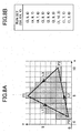
- FIGS. 9A and 9B are diagrams for explaining the clip path.
- FIG. 9A shows the flip path
- FIG. 9B shows the run set thereof.
- the line run generator 24 converts the clip path into the line run, similarly to the conversion of the graphic path.
- the region run generator 25 converts the line run into the region run, similarly to the conversion of the line run which is converted from the graphic path.
- the region run which is generated by the region run generator 25 corresponds to a rectangular region indicated in hatching in FIG. 9A, and FIG. 9B shows the coordinates of the run set for this particular case.
- the region run generated by the region run generator 25 is stored in the clip region run storage 27.
- the process ends when the clip region run generated by the region run generator 25 is stored in the clip region run storage 27, and the image processing apparatus 21 prepares to process the subsequent input of the graphic path.
- the clip region run By storing the clip region run until a clip path is input the next time, it is possible to re-use the stored clip region run during the subsequent processing of the graphic region run.
- the plot region run generator 28 extracts an overlapping portion between the graphic region run stored in the graphic region run storage 26 and the clip region run stored in the clip region run storage 27, so as to obtain a plot region run.
- FIGS. 10A, 10B, 10C and 10D are diagrams for explaining the graphic region run, the clip region run and the plot region run.
- FIG. 10A shows the graphic region run for the graphic shown in FIG. 8A
- FIG. 10B shows the clip region run generated from the clip path shown in FIG. 9A
- FIG. 10C shows the plot region run obtained from the graphic region run shown in FIG. 10A and the clip region run shown in FIG. 10B.
- FIG. 10D shows the run set of the clip region run show in FIG. 10C.
- the graphic region run storage 26 may be used to store the generated plot region run by overwriting the plot region run in the graphic region run storage 26.
- a memory may be provided separately from the graphic region run storage 26 to store the generated plot region run. This memory may be provided within the plot region run generator 28 or, externally to the plot region run generator 28.
- the plot section 29 carries out a plotting process with respect to a corresponding region of the image memory 30 using the plot region run generated by the plot region run generator 28 and the plot attribute information such as the colors and the ROP.
- the run stored in the image memory 30 is output to the image output apparatus 31 in response to the end of the plot instruction or in response to the output instruction.
- FIGS. 11A and 11B are diagrams for explaining the process of converting 2 line vectors having the same Y-coordinate direction into 1 line run.
- FIG. 11A shows the line vectors
- FIG. 11B shows the run set and the Y direction of the line run.
- the 2 line vectors are the line vector L1(P1, P2) and the line vector L2(P2, P3) having the downward direction with respect to the Y-coordinates as shown in FIG. 11A.
- the line run is first generated with respect to each of the line vectors L1(P1, P2) and L2(P2, P3).
- the 2 line runs which are generated overlap in only the Y-coordinates including the intersecting point P2.
- the portion of the Y-coordinates (Y 1 to 4), excluding a starting run of L2, becomes the resulting line run as it is.
- the smaller one of the starting point X and the larger one of the terminating point are respectively regarded as the starting point X and the terminating point X of the combined run.
- the present invention is not limited to combining 2 line vectors into a single line run, and the number of line vectors to be combined may be arbitrary as long as the line vectors are in the same Y-coordinate direction.
- By combining the plurality of line vectors into the single line run it is possible to reduce the number of line runs to be processed in the region run generator 25, thereby enabling a high-speed processing in the image processing apparatus 21.
- the image processing carried out by the image processing apparatus 21 includes a rasterizing process which is suited for rasterizing graphic data of an arbitrary graphic, so as to store bit map data of the arbitrary graphic in the image memory 30.
- This rasterizing process includes a scan line conversion carried out by the line run generator 24 and the region run generator 25, and a clipping carried out by the plot region run generator 28 using the graphic region run storage 26 and the clip region run storage 27.
- the scan line conversion converts line vectors of an input graphic path and an input clip path into run sets in the dot coordinates passed by the line vectors, and generates a run set (region run) describing a closed region represented by the entire path, from the run sets obtained. As a result, a graphic region run and a clip region run are obtained and stored.
- the clipping extracts an overlapping portion of the-graphic region run and the clip region run, and generates a plot region run.
- a plotting may be carried out by the plot section 29 to plot and store the plot region run in the image memory 30 in the form of bit map data.
- FIG. 12 is a system block diagram showing a computer system to which the image processing method and the image processing apparatus according to the present invention may be applied.
- the computer system shown in FIG. 12 includes a computer 41 and an image output apparatus 42 which are coupled via a connecting means 43.
- the computer 41 may be formed by a personal computer having a known structure including at least one processor such as a CPU and a computer-readable storage medium such as a storage unit and a memory.
- the connecting means 43 may be formed by any cable and/or wireless connecting means or, any cable and/or wireless network, which can make the necessary connections between the computer 41 and the image output apparatus 42.
- the image output apparatus 42 is formed by a printer or a display unit having a known structure including at least one processor such as a CPU and a computer-readable storage medium such as a storage unit and a memory.
- the computer 41 includes applications 411 which are executed by the CPU thereof, a graphic interface 412 which outputs a plot instruction responsive to the applications 411, and a driver 413 which outputs image data responsive to the plot instruction.
- This driver 413 is a printer driver in a case where the image output apparatus 42 is a printer, and is a display driver in a case where the image output apparatus 42 is a display unit.
- the image output apparatus 42 includes applications 421 which are executed by the CPU thereof, a memory 422 which stores bit map data of the image data, and an engine 423 which receives the bit map data to be output.
- the memory 422 may be formed by a portion of the computer-readable storage medium of the image output apparatus 42.
- the engine 423 is a printer engine in the case where the image-output apparatus 42 is a printer, and is a display engine in the case where the image output apparatus 42 is a display unit.
- a rasterizing program (computer software) for causing the CPU of the image output apparatus 42 to carrying out the rasterizing process described above is provided in the applications 421.
- the provision of the rasterizing program in the image output apparatus 42 is effective when the processing capability and speed of the computer 41 are not very high, because the load on the CPU of the computer 41 can be reduced.
- the rasterizing program in the image output apparatus 42 it is possible to provide the rasterizing program in the driver 413 within the computer 41.
- the provision of the rasterizing program in the computer 41 is effective when the processing capability and speed of the computer 41 are high, because the rasterizing process can be carried out at a high speed within the computer 41.
- the rasterizing program described above is stored in a computer-readable storage medium within the computer 41 or the image output apparatus 42 shown in FIG. 12.
- the computer 41 forms another embodiment of the image processing apparatus according to the present invention.
- the computer-readable storage medium may be formed by any recording media capable of storing a computer program, such as semiconductor memory devices, magnetic recording media, optical recording media and magneto-optical recording media such as disks and cards.
- the computer-readable storage medium may be portable.
- the rasterizing program may be provided in a CD-ROM or the like which stores the printer driver or the display driver forming the driver 413.
- the line vector forming the path is converted into the line run at an initial stage of the process to make a conversion from the real number coordinates to the integer coordinates, so that the subsequent generation of the region run and the clipping may be made solely by integer computations.
- the present invention makes the real number computations in one operation at the time when the conversion to the line run is made, and not for every scan line Y-coordinate unit as in the case of the conventional method. For this reason, the image processing as a whole can be carried out at a high speed according to the present invention.
- the present invention can carry out the clipping at a high speed, because the real number computations such as obtaining intersecting points with respect to the graphic path can be omitted in the present invention.
- the graphic path and the clip path form an arbitrary closed region including a convex type, a concave type and a self-intersecting type by one or a plurality of runs (run set).
- each line vector forming the path can be converted independently into the line run, irrespective of the positional relationship of the vectors. For this reason, it is unnecessary to judge the shape, and the image processing can be carried out at a high speed.
- the line run which is generated inherits the Y-coordinate direction (upward direction, downward direction and horizontal) of the path which is the generating source, as accessory information.
- the line run which is generated inherits the Y-coordinate direction (upward direction, downward direction and horizontal) of the path which is the generating source, as accessory information.
- the computation process can be carried out at a high speed when generating the region run in the region run generator 25, by sorting all line runs by the starting point Y-coordinates, extracting the line run included in an arbitrary Y-coordinate, sorting the starting point X and the terminating point X of the line run by the starting point X, making the X range definite by an arbitrary scan line conversion rule such as the non-zero winding rule and the even-odd rule, and generating the region run by carrying out these processes with respect to all Y-coordinates.
- the printer may be any type of printer, including laser printers and ink-jet printers.
- the display unit may be any type of display unit, including cathode ray tubes (CRTs), liquid crystal displays (LCDs), plasma display panels (PDPs) and the like.
Applications Claiming Priority (2)
| Application Number | Priority Date | Filing Date | Title |
|---|---|---|---|
| JP2001359449A JP2003162728A (ja) | 2001-11-26 | 2001-11-26 | 画像処理装置及び画像出力装置 |
| JP2001359449 | 2001-11-26 |
Publications (2)
| Publication Number | Publication Date |
|---|---|
| EP1315126A2 true EP1315126A2 (de) | 2003-05-28 |
| EP1315126A3 EP1315126A3 (de) | 2005-01-26 |
Family
ID=19170451
Family Applications (1)
| Application Number | Title | Priority Date | Filing Date |
|---|---|---|---|
| EP20020257960 Withdrawn EP1315126A3 (de) | 2001-11-26 | 2002-11-19 | Bildverarbeitungsverfahren und -vorrichtung, Bildausgabe-Anlage und Speichermedium |
Country Status (3)
| Country | Link |
|---|---|
| US (1) | US6956584B2 (de) |
| EP (1) | EP1315126A3 (de) |
| JP (1) | JP2003162728A (de) |
Cited By (1)
| Publication number | Priority date | Publication date | Assignee | Title |
|---|---|---|---|---|
| AU2008260018B2 (en) * | 2008-12-18 | 2010-09-23 | Canon Kabushiki Kaisha | Refining text extraction in colour compound documents |
Families Citing this family (6)
| Publication number | Priority date | Publication date | Assignee | Title |
|---|---|---|---|---|
| US7181054B2 (en) * | 2001-08-31 | 2007-02-20 | Siemens Medical Solutions Health Services Corporation | System for processing image representative data |
| JP2006085276A (ja) * | 2004-09-14 | 2006-03-30 | Seiko Epson Corp | 画像処理装置、画像処理方法及びそのプログラム |
| US8878851B2 (en) * | 2004-11-12 | 2014-11-04 | Synchronica Plc | Method and system for streaming documents, e-mail attachments and maps to wireless devices |
| US7436414B2 (en) * | 2004-11-12 | 2008-10-14 | Valve Corporation | Method for accelerated determination of occlusion between polygons |
| JP6930337B2 (ja) * | 2017-09-27 | 2021-09-01 | カシオ計算機株式会社 | 電子機器、移動経路記録方法、およびプログラム |
| US10803174B2 (en) * | 2018-09-15 | 2020-10-13 | Quantum Star Technologies LLC | Bit-level data generation and artificial intelligence techniques and architectures for data protection |
Citations (6)
| Publication number | Priority date | Publication date | Assignee | Title |
|---|---|---|---|---|
| US4758965A (en) * | 1985-10-09 | 1988-07-19 | International Business Machines Corporation | Polygon fill processor |
| EP0402161A2 (de) * | 1989-06-09 | 1990-12-12 | Xerox Corporation | Darstellung von Polygonen, die mit nichtnull umwickelnden Zahlen definiert sind |
| US5444834A (en) * | 1990-07-31 | 1995-08-22 | Kabushiki Kaisha Toshiba | Filling pattern generation apparatus and method including correction for pattern overflow |
| US5966136A (en) * | 1995-04-12 | 1999-10-12 | Hewlett-Packard Co. | Efficient method for clipping numerous objects against an arbitrary clipping path |
| EP0964367A2 (de) * | 1998-06-08 | 1999-12-15 | Matsushita Electric Industrial Co., Ltd. | Figurfüllungsgerät |
| US6288724B1 (en) * | 1998-09-16 | 2001-09-11 | Texas Instruments Incorporated | Clipping and trapezoid decomposition of polygons for printing files in a page description language |
Family Cites Families (2)
| Publication number | Priority date | Publication date | Assignee | Title |
|---|---|---|---|---|
| US6424430B1 (en) * | 1998-04-06 | 2002-07-23 | Adobe Systems Incorporated | Rendering of objects on graphical rendering devices as clipped images |
| JP3266905B2 (ja) | 1998-09-09 | 2002-03-18 | 富士ゼロックス株式会社 | 図形処理装置 |
-
2001
- 2001-11-26 JP JP2001359449A patent/JP2003162728A/ja active Pending
-
2002
- 2002-11-19 EP EP20020257960 patent/EP1315126A3/de not_active Withdrawn
- 2002-11-21 US US10/300,586 patent/US6956584B2/en not_active Expired - Fee Related
Patent Citations (6)
| Publication number | Priority date | Publication date | Assignee | Title |
|---|---|---|---|---|
| US4758965A (en) * | 1985-10-09 | 1988-07-19 | International Business Machines Corporation | Polygon fill processor |
| EP0402161A2 (de) * | 1989-06-09 | 1990-12-12 | Xerox Corporation | Darstellung von Polygonen, die mit nichtnull umwickelnden Zahlen definiert sind |
| US5444834A (en) * | 1990-07-31 | 1995-08-22 | Kabushiki Kaisha Toshiba | Filling pattern generation apparatus and method including correction for pattern overflow |
| US5966136A (en) * | 1995-04-12 | 1999-10-12 | Hewlett-Packard Co. | Efficient method for clipping numerous objects against an arbitrary clipping path |
| EP0964367A2 (de) * | 1998-06-08 | 1999-12-15 | Matsushita Electric Industrial Co., Ltd. | Figurfüllungsgerät |
| US6288724B1 (en) * | 1998-09-16 | 2001-09-11 | Texas Instruments Incorporated | Clipping and trapezoid decomposition of polygons for printing files in a page description language |
Cited By (2)
| Publication number | Priority date | Publication date | Assignee | Title |
|---|---|---|---|---|
| AU2008260018B2 (en) * | 2008-12-18 | 2010-09-23 | Canon Kabushiki Kaisha | Refining text extraction in colour compound documents |
| AU2008260018C1 (en) * | 2008-12-18 | 2011-01-20 | Canon Kabushiki Kaisha | Refining text extraction in colour compound documents |
Also Published As
| Publication number | Publication date |
|---|---|
| JP2003162728A (ja) | 2003-06-06 |
| US20030112254A1 (en) | 2003-06-19 |
| US6956584B2 (en) | 2005-10-18 |
| EP1315126A3 (de) | 2005-01-26 |
Similar Documents
| Publication | Publication Date | Title |
|---|---|---|
| JP4030519B2 (ja) | 画像処理装置および画像処理システム | |
| US20080285889A1 (en) | Image transform method for obtaining expanded image data, image processing apparatus and image display device therefore | |
| US5966136A (en) | Efficient method for clipping numerous objects against an arbitrary clipping path | |
| US5524198A (en) | Character or graphic processing method and apparatus | |
| US6956584B2 (en) | Image processing method, image processing apparatus, image output apparatus and storage medium | |
| JP3791259B2 (ja) | アウトラインスムージング処理方法 | |
| EP0344686A2 (de) | Abschneidungsverfahren und -verarbeitungsgerät | |
| US6201553B1 (en) | Character generating method and apparatus | |
| JP3009525B2 (ja) | ベクトル画像描画装置 | |
| JPH10337932A (ja) | 印刷処理装置 | |
| US6504543B1 (en) | Polygon drawing method and polygon drawing apparatus | |
| US8605112B2 (en) | Graphics drawing apparatus, method, and program and recording medium on which the program is recorded | |
| JP3146771B2 (ja) | フォントラスタライズ装置およびその方法 | |
| EP0479496A2 (de) | Hochgeschwindigkeits-graphische Bilderzeugung mit mehreren Sequenzvorrichtungen | |
| JP3823730B2 (ja) | 画像処理装置及びその方法 | |
| JPH10151815A (ja) | 印刷処理装置 | |
| US20220262053A1 (en) | Image processing apparatus, image processing method, and program | |
| JP4863306B2 (ja) | ベクターイメージ描画装置、ベクターイメージ描画方法およびプログラム | |
| JP2000066658A (ja) | 画像処理装置および記録媒体 | |
| JPH1021415A (ja) | 図形処理装置並びに図形処理方法 | |
| JP2888270B2 (ja) | 図形処理装置及びその方法 | |
| JPH11232473A (ja) | 印刷処理装置 | |
| JP2000222569A (ja) | 描画装置 | |
| JPH11157147A (ja) | 印刷処理装置および印刷処理方法 | |
| JP2000259844A (ja) | 描画処理装置および描画処理方法 |
Legal Events
| Date | Code | Title | Description |
|---|---|---|---|
| PUAI | Public reference made under article 153(3) epc to a published international application that has entered the european phase |
Free format text: ORIGINAL CODE: 0009012 |
|
| 17P | Request for examination filed |
Effective date: 20021119 |
|
| AK | Designated contracting states |
Designated state(s): AT BE BG CH CY CZ DE DK EE ES FI FR GB GR IE IT LI LU MC NL PT SE SK TR |
|
| AX | Request for extension of the european patent |
Extension state: AL LT LV MK RO SI |
|
| PUAL | Search report despatched |
Free format text: ORIGINAL CODE: 0009013 |
|
| AK | Designated contracting states |
Kind code of ref document: A3 Designated state(s): AT BE BG CH CY CZ DE DK EE ES FI FR GB GR IE IT LI LU MC NL PT SE SK TR |
|
| AX | Request for extension of the european patent |
Extension state: AL LT LV MK RO SI |
|
| AKX | Designation fees paid |
Designated state(s): DE FR GB IT NL |
|
| 17Q | First examination report despatched |
Effective date: 20061201 |
|
| STAA | Information on the status of an ep patent application or granted ep patent |
Free format text: STATUS: THE APPLICATION IS DEEMED TO BE WITHDRAWN |
|
| 18D | Application deemed to be withdrawn |
Effective date: 20150729 |