EP1314836A2 - Vorrichtung zur Montage von plattenförmigen Bauelementen - Google Patents
Vorrichtung zur Montage von plattenförmigen Bauelementen Download PDFInfo
- Publication number
- EP1314836A2 EP1314836A2 EP02025427A EP02025427A EP1314836A2 EP 1314836 A2 EP1314836 A2 EP 1314836A2 EP 02025427 A EP02025427 A EP 02025427A EP 02025427 A EP02025427 A EP 02025427A EP 1314836 A2 EP1314836 A2 EP 1314836A2
- Authority
- EP
- European Patent Office
- Prior art keywords
- guide ring
- base body
- elements
- plate
- receiving element
- Prior art date
- Legal status (The legal status is an assumption and is not a legal conclusion. Google has not performed a legal analysis and makes no representation as to the accuracy of the status listed.)
- Granted
Links
Images


Classifications
-
- B—PERFORMING OPERATIONS; TRANSPORTING
- B66—HOISTING; LIFTING; HAULING
- B66C—CRANES; LOAD-ENGAGING ELEMENTS OR DEVICES FOR CRANES, CAPSTANS, WINCHES, OR TACKLES
- B66C1/00—Load-engaging elements or devices attached to lifting or lowering gear of cranes or adapted for connection therewith for transmitting lifting forces to articles or groups of articles
- B66C1/02—Load-engaging elements or devices attached to lifting or lowering gear of cranes or adapted for connection therewith for transmitting lifting forces to articles or groups of articles by suction means
- B66C1/0212—Circular shape
-
- B—PERFORMING OPERATIONS; TRANSPORTING
- B66—HOISTING; LIFTING; HAULING
- B66C—CRANES; LOAD-ENGAGING ELEMENTS OR DEVICES FOR CRANES, CAPSTANS, WINCHES, OR TACKLES
- B66C1/00—Load-engaging elements or devices attached to lifting or lowering gear of cranes or adapted for connection therewith for transmitting lifting forces to articles or groups of articles
- B66C1/02—Load-engaging elements or devices attached to lifting or lowering gear of cranes or adapted for connection therewith for transmitting lifting forces to articles or groups of articles by suction means
- B66C1/0237—Multiple lifting units; More than one suction area
- B66C1/0243—Separate cups
-
- E—FIXED CONSTRUCTIONS
- E04—BUILDING
- E04G—SCAFFOLDING; FORMS; SHUTTERING; BUILDING IMPLEMENTS OR AIDS, OR THEIR USE; HANDLING BUILDING MATERIALS ON THE SITE; REPAIRING, BREAKING-UP OR OTHER WORK ON EXISTING BUILDINGS
- E04G21/00—Preparing, conveying, or working-up building materials or building elements in situ; Other devices or measures for constructional work
- E04G21/14—Conveying or assembling building elements
- E04G21/16—Tools or apparatus
-
- E—FIXED CONSTRUCTIONS
- E04—BUILDING
- E04G—SCAFFOLDING; FORMS; SHUTTERING; BUILDING IMPLEMENTS OR AIDS, OR THEIR USE; HANDLING BUILDING MATERIALS ON THE SITE; REPAIRING, BREAKING-UP OR OTHER WORK ON EXISTING BUILDINGS
- E04G21/00—Preparing, conveying, or working-up building materials or building elements in situ; Other devices or measures for constructional work
- E04G21/14—Conveying or assembling building elements
- E04G21/16—Tools or apparatus
- E04G21/167—Tools or apparatus specially adapted for working-up plates, panels or slab shaped building elements
Definitions
- the invention relates to a device for mounting plate-shaped components according to the preamble of Claim 1.
- the object of the invention is to propose a device by means of the plate-shaped components in the space between conventional scaffolding and the facade level of a building and easy on site are to be aligned.
- This task is based on a device of initially mentioned type by the characteristic features of the Claim 1 solved.
- one according to the invention is distinguished Device characterized in that the storage means for rotatable suspension of one or more holding elements are arranged outside the axis of rotation of the rotary movement.
- the or said holding elements attached to a base body the is in turn rotatably supported.
- the holding element or elements can be mechanical, pneumatic, hydraulic and / or magnetic holding elements be trained. Basically, all currently known and used to become known holding elements that are suitable, corresponding plate-shaped Hold components.
- the rotary movement in one Provide a rotation angle of at least 360 °, e.g. rotatability in two directions by 180 °.
- a rotation angle of at least 360 ° e.g. rotatability in two directions by 180 °.
- a Guide ring for mounting the holding element preferably in Connection provided with the basic body mentioned above.
- Storage of the rotary motion can be realized without being on site a bearing in one Swivel is provided.
- the guide ring will be like this executed that he too with the hoist mentioned connect is.
- the guide ring rigidly attached to the base body, with a corresponding Provide receiving element for connection to the hoist on which the guide ring is rotatably suspended.
- a rotatable suspension be rigidly attached to the base body guide ring preferably rolling elements between the guide ring and the Receiving element provided that a rotation of the Allow the guide ring by rolling on the rolling elements.
- the Base body rotatably attached to the guide ring.
- the guide ring can be a firmly connected Include receiving element for connection to a hoist.
- the rolling elements for both of the above-mentioned embodiments are preferably used as roller bearings and / or cage-guided Ball bearings designed.
- both above described embodiments will be at least one Damping and / or locking device for the rotary movement intended. This should result in uncontrolled rotary movements the fixed to the base body via the holding elements plate-shaped components during the process and Assembly can be avoided.
- damping and locking elements can be force or be form-fitting.
- a positive damping or determination can be a or Multiple friction bodies are provided that are caused by friction dampen the rotary movement on the guide ring or on the base body or completely prevent it. Through the contact pressure
- Such a friction body can be the rotational resistance if necessary, can be set variably.
- a non-positive damping or determination would be for example, in particular by a magnetic brake an eddy current brake can be implemented.
- the energy supply elements can be in the form, for example of batteries or accumulators, pressure accumulators etc. be formed.
- the controls can be in addition to electronic components also pneumatic and / or hydraulic control elements, e.g. Control valves or the like include.
- One or more drive units are therefore advantageously also on the base body assembled.
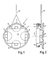
- the first embodiment according to Figures 1 and 2 shows a device 1 according to the invention with a guide ring 2 and a base body 3, the guide ring 2 in Figure 1 not shown rigid with the Base body 3 is connected.
- the connecting elements 4, 5 can be seen in the side view of Figure 2.
- the base body 3 There are four holding elements 6, 7, 8, 9 on the base body 3 attached in the form of suction lifters, for example. If necessary, the holding elements 6, 7, 8, 9 for Adaptation to the plate-shaped components to be held mobile, e.g. slidable in one or more directions to be appropriate.
- the guide ring 2 lies on two Bearing rollers 10, 11 of a sketchy Receiving element 12 on.
- the receiving element 12 is not in shown in more detail for connection to a hoist, e.g. designed a crane or the like, wherein it is ensured that the bearing rollers 10, 11 on the same Height and fixed at a predetermined distance.
- the guide ring 2 in the illustrated embodiment is formed from round tube, the in the bearing rollers 10, 11 in the corresponding concave Counter profile is guided.
- the guide ring 2 together with the The base body 3 is accordingly on the bearing rollers 10, 11 pivoted about the axis of rotation D without in the area of Axis of rotation D corresponding bearing elements are provided.
- FIG. 13 Another embodiment is shown in FIG the guide ring 13 is fixed via fastening tabs 14, 15 is attached to the receiving element 16.
- the base body 17 with fork-shaped Roller carriers 18, 19, 20, 21 provided, in which rollers 22, 23, 24, 25 are rotatably mounted.
- rollers 22, 23, 24, 25 With the help of the rollers 22, 23, 24, 25 is the base body 17 about the central axis D. rotatably supported in the guide ring 13.
- the guide ring 13 here again has a tubular profile, so that the Casters 22, 23, 24, 25 with a corresponding concave profile are captively guided on the guide ring 13 (see FIG. 4).
- the base body 17 is also in this embodiment four holding elements, for example suction cups, to one plate-shaped component, not shown hold.
- FIG. 5 essentially corresponds the above-described with reference to Figure 3 Embodiment. Now, however, is an additional one Provided friction element 30, the guide ring 13th encompasses at least partially on both sides.
- Friction element 30 with two brake shoes 31 more clearly shown.
- the two brake shoes 31, 32 are over Pivots 33, 34 rotatably attached to the bracket 35.
- she can via a sketch lever 36 actuated, i.e. solved in the direction of the double arrow P or in reverse direction for braking or locking the Rotational movement can be braced.
- FIG. 7 shows a base body 3 with guide ring 2, as in Embodiment according to Figure 1.
- a vacuum pump 37 for those designed as suction cups Holding elements 6, 7, 8, 9.
- a control 38, an operating part 39, a flashing light 40 and a warning horn 41 attached to the base body 3.
- a Vacuum tank 42, batteries or accumulators 43, 44 and one Multi-way valve 45 There are also a Vacuum tank 42, batteries or accumulators 43, 44 and one Multi-way valve 45.
- the vacuum pump is also included a check valve 46 provided. Also a pressure switch 47 or a multi-way valve 45 are for the controlled Operating procedure provided.
- the various units, control and warning elements serve the various functions of the device 1.
- An operator 39 can take the picture via the operating part 39 and the release of the plate-shaped component and the Control movements of device 1.
- a flashing light as well A warning horn serves as an alarm in the event of a Malfunction.
- the batteries 43, 44 supply all electrical components, in particular the controller 38 with the required electrical energy.
- the vacuum pump 37 with the Check valve 46 ensures the reliable function of the Sucker, with the vacuum tank 42 increasing Operational safety guaranteed.
- feeders for example electrical feeders or pneumatic Feeds via rotary unions or sliding contacts from coupled externally to the base body 3 and its components become.
Landscapes
- Engineering & Computer Science (AREA)
- Architecture (AREA)
- Mechanical Engineering (AREA)
- Civil Engineering (AREA)
- Structural Engineering (AREA)
- Magnetic Bearings And Hydrostatic Bearings (AREA)
- Piezo-Electric Or Mechanical Vibrators, Or Delay Or Filter Circuits (AREA)
- Non-Reversible Transmitting Devices (AREA)
- Conveying And Assembling Of Building Elements In Situ (AREA)
- Load-Bearing And Curtain Walls (AREA)
Abstract
Description
- Figur 1
- eine Draufsicht auf eine erfindungsgemäße Vorrichtung,
- Figur 2
- eine Seitenansicht einer Vorrichtung gemäß Figur 1,
- Figur 3
- eine Draufsicht auf eine weitere Ausführungsform der Erfindung,
- Figur 4
- eine Ausschnittsvergrößerung aus Figur 3 im Schnitt,
- Figur 5
- eine Weiterbildung der Vorrichtung gemäß Figur 3 in der Draufsicht,
- Figur 6
- eine Ausschnittsvergrößerung aus Figur 5 in Schnittdarstellung und
- Figur 7
- eine Draufsicht auf einen Grundkörper für eine Vorrichtung gemäß den Figuren 3 und 5.
- 1
- Vorrichtung
- 2
- Führungsring
- 3
- Grundkörper
- 4
- Verbindungselement
- 5
- Verbindungselement
- 6
- Halteelement
- 7
- Halteelement
- 8
- Halteelement
- 9
- Halteelement
- 10
- Lagerrolle
- 11
- Lagerrolle
- 12
- Aufnahmeelement
- 13
- Führungsring
- 14
- Befestigungslasche
- 15
- Befestigungslasche
- 16
- Aufnahmeelement
- 17
- Grundkörper
- 18
- Rollenträger
- 19
- Rollenträger
- 20
- Rollenträger
- 21
- Rollenträger
- 22
- Laufrolle
- 23
- Laufrolle
- 24
- Laufrolle
- 25
- Laufrolle
- 26
- Halteelement
- 27
- Halteelement
- 28
- Halteelement
- 29
- Halteelement
- 30
- Friktionselement
- 31
- Bremsbacke
- 32
- Bremsbacke
- 33
- Drehbolzen
- 34
- Drehbolzen
- 35
- Halterung
- 36
- Spannhebel
- 37
- Vakuumpumpe
- 38
- Steuerung
- 39
- Bedienteil
- 40
- Blinkleuchte
- 41
- Warnhupe
- 42
- Vakuumtank
- 43
- Batterie
- 44
- Batterie
- 45
- Mehrwegeventil
- 46
- Rückschlagventil
- 47
- Druckschalter
Claims (17)
- Vorrichtung zur Montage von plattenförmigen Bauelementen, insbesondere Glasplatten, Fassadenelementen oder dergleichen, die wenigstens ein Halteelement aufweist, das mit Lagermitteln drehbar um eine im Wesentlichen horizontale Achse gelagert und mit einem Hebezeug verbindbar ist, dadurch gekennzeichnet, dass die Lagerungsmittel (2, 10, 11) außerhalb der Drehachse D der Drehbewegung angeordnet sind.
- Vorrichtung nach Anspruch 1, dadurch gekennzeichnet, dass das Halteelement (6, 7, 8, 9) als mechanisches, pneumatisches, hydraulisches und/oder magnetisches Element ausgebildet ist.
- Vorrichtung nach einem der vorgenannten Ansprüche, dadurch gekennzeichnet, dass das Halteelement (6, 7, 8, 9) an einem drehbar gelagerten Grundkörper (3) befestigt ist.
- Vorrichtung nach einem der vorgenannten Ansprüche, dadurch gekennzeichnet, dass für die Drehbewegung ein Drehwinkel von mindestens 360° in einer Drehrichtung bzw. um mindestens 180° in jeweils zwei entgegengesetzte Richtungen vorgesehen ist.
- Vorrichtung nach einem der vorgenannten Ansprüche, dadurch gekennzeichnet, dass die Lagerungsmittel einen Führungsring (2) umfassen.
- Vorrichtung nach einem der vorgenannten Ansprüche, dadurch gekennzeichnet, dass der Grundkörper (3) innerhalb des Führungsrings (2) angeordnet ist.
- Vorrichtung nach einem der vorgenannten Ansprüche, dadurch gekennzeichnet, dass der Führungsring (2) starr am Grundkörper (3) befestigt ist.
- Vorrichtung nach einem der vorgenannten Ansprüche, dadurch gekennzeichnet, dass ein Aufnahmeelement (12) vorgesehen ist, an den der Führungsring (2) rotierbar aufgehängt ist.
- Vorrichtung nach einem der vorgenannten Ansprüche, dadurch gekennzeichnet, dass das Aufnahmeelement Rollelemente (10, 11) für den Führungsring umfasst.
- Vorrichtung nach einem der vorgenannten Ansprüche, dadurch gekennzeichnet, dass der Grundkörper (17) rotierbar am Führungsring (13) gelagert ist.
- Vorrichtung nach einem der vorgenannten Ansprüche, dadurch gekennzeichnet, dass Rollelemente (22, 23, 24, 25) zur Lagerung des Grundkörpers (17) am Führungsring (13) vorgesehen sind.
- Vorrichtung nach einem der vorgenannten Ansprüche, dadurch gekennzeichnet, dass die Rollelemente zur Aufhängung des Führungsrings (2) am Aufnahmeelement (12) bzw. zur Befestigung des Grundkörpers (17) am Führungsring (13) ein Rollenlager und/oder ein käfiggeführtes Kugellager umfassen.
- Vorrichtung nach einem der vorgenannten Ansprüche, dadurch gekennzeichnet, dass eine Dämpfungs- und/oder Feststellvorrichtung (30, 31, 32) für die Dämpfung oder Feststellung der Drehbewegung vorgesehen ist.
- Vorrichtung nach einem der vorgenannten Ansprüche, dadurch gekennzeichnet, dass das Dämpfungs- und/oder Feststellelement ein Friktionselement (30) umfasst.
- Vorrichtung nach einem der vorgenannten Ansprüche, dadurch gekennzeichnet, dass Energieversorgungselemente (43, 44) und/oder Steuerelemente (38) am Grundkörper (3) angebracht sind.
- Vorrichtung nach einem der vorgenannten Ansprüche, dadurch gekennzeichnet, dass Energie- und/oder Steuerleitungen über Schleifkontakte bzw. Drehdurchführungen an dem Grundkörper (3) angekoppelt sind.
- Verfahren zur Montage von plattenförmigen Bauelementen, insbesondere zur Herstellung von Gebäudefassaden, dadurch gekennzeichnet, dass eine Vorrichtung nach einem der vorgenannten Ansprüche verwendet wird.
Applications Claiming Priority (2)
| Application Number | Priority Date | Filing Date | Title |
|---|---|---|---|
| DE10157718A DE10157718B4 (de) | 2001-11-24 | 2001-11-24 | Vorrichtung zur Montage von plattenförmigen Bauelementen |
| DE10157718 | 2001-11-24 |
Publications (3)
| Publication Number | Publication Date |
|---|---|
| EP1314836A2 true EP1314836A2 (de) | 2003-05-28 |
| EP1314836A3 EP1314836A3 (de) | 2004-02-11 |
| EP1314836B1 EP1314836B1 (de) | 2006-08-16 |
Family
ID=7706866
Family Applications (1)
| Application Number | Title | Priority Date | Filing Date |
|---|---|---|---|
| EP02025427A Expired - Lifetime EP1314836B1 (de) | 2001-11-24 | 2002-11-15 | Vorrichtung zur Montage von plattenförmigen Bauelementen |
Country Status (3)
| Country | Link |
|---|---|
| EP (1) | EP1314836B1 (de) |
| AT (1) | ATE336457T1 (de) |
| DE (2) | DE10157718B4 (de) |
Cited By (1)
| Publication number | Priority date | Publication date | Assignee | Title |
|---|---|---|---|---|
| DE102019104590B3 (de) * | 2019-02-22 | 2020-04-16 | Bohle Ag | Haltekopf für eine Vakuum-Haltevorrichtung zur Handhabung eines plattenförmigen Werkstücks und entsprechende Vakuum-Haltevorrichtung |
Families Citing this family (1)
| Publication number | Priority date | Publication date | Assignee | Title |
|---|---|---|---|---|
| DE102020006234A1 (de) | 2020-10-09 | 2022-04-14 | Andreas Hein | Montagehilfe |
Family Cites Families (2)
| Publication number | Priority date | Publication date | Assignee | Title |
|---|---|---|---|---|
| DE3834311A1 (de) * | 1988-10-08 | 1990-04-12 | Kessler & Luch Produkte | Hilfsvorrichtung zum montieren von platten |
| DE9404897U1 (de) * | 1994-03-18 | 1994-09-22 | Siemens AG, 80333 München | Rangiergerät |
-
2001
- 2001-11-24 DE DE10157718A patent/DE10157718B4/de not_active Expired - Fee Related
-
2002
- 2002-11-15 EP EP02025427A patent/EP1314836B1/de not_active Expired - Lifetime
- 2002-11-15 AT AT02025427T patent/ATE336457T1/de active
- 2002-11-15 DE DE50207844T patent/DE50207844D1/de not_active Expired - Lifetime
Cited By (3)
| Publication number | Priority date | Publication date | Assignee | Title |
|---|---|---|---|---|
| DE102019104590B3 (de) * | 2019-02-22 | 2020-04-16 | Bohle Ag | Haltekopf für eine Vakuum-Haltevorrichtung zur Handhabung eines plattenförmigen Werkstücks und entsprechende Vakuum-Haltevorrichtung |
| EP3699134A1 (de) | 2019-02-22 | 2020-08-26 | Bohle AG | Haltekopf für eine vakuum-haltevorrichtung zur handhabung eines plattenförmigen werkstücks und entsprechende vakuum-haltevorrichtung |
| US11458598B2 (en) | 2019-02-22 | 2022-10-04 | Bohle Ag | Holding head for a vacuum holding device for handling a plate-shaped workpiece and corresponding vacuum holding device |
Also Published As
| Publication number | Publication date |
|---|---|
| EP1314836A3 (de) | 2004-02-11 |
| ATE336457T1 (de) | 2006-09-15 |
| DE50207844D1 (de) | 2006-09-28 |
| EP1314836B1 (de) | 2006-08-16 |
| DE10157718A1 (de) | 2003-06-26 |
| DE10157718B4 (de) | 2007-08-23 |
Similar Documents
| Publication | Publication Date | Title |
|---|---|---|
| EP2602415B1 (de) | Schiebetüranordnung | |
| DE69314475T2 (de) | Schiebetür und steuerungsvorrichtung zum öffnen und schliessen einer in einem fahrzeug horizontal schiebende tür | |
| DE102010016155A1 (de) | Lenkrolle | |
| DE3927653A1 (de) | Halterung fuer eine biegemomentfreie lagerung von wand- oder deckenplatten | |
| EP3020901B1 (de) | Rollenwagen für die Aufnahme einer Schiebetür mit zumindest zwei Montagevorrichtungen | |
| DE102010051126A1 (de) | Operationstisch | |
| DE2914844C2 (de) | Schnellspannvorrichtung, insbesondere für Auswuchtmaschinen zum Auswuchten von Fahrzeugrädern | |
| DE60201003T2 (de) | Türantrieb | |
| WO2017036697A1 (de) | Luftfeder für ein kraftfahrzeug | |
| WO2002064924A2 (de) | Sicherungvorrichtung gegen ungewolltes auslenken einer türflügel | |
| DE10157718B4 (de) | Vorrichtung zur Montage von plattenförmigen Bauelementen | |
| EP0004677B1 (de) | Vorrichtung zum Abdichten und Schliessen von Feuerschutzabschlüssen | |
| DE102005005991A1 (de) | Konsole für eine drehbare Sitz- und Bedieneinheit eines Nutzfahrzeugs | |
| DE69008348T2 (de) | Vorrichtung zur Schwingungsdämpfung an einer Verladeeinrichtung. | |
| EP3523160B1 (de) | Getriebeanordnung für einen spindelantrieb, spindelantrieb und fahrzeugsitz | |
| WO2006111032A1 (de) | Endlageeinzugs- und endlagedämpfungsvorrichtung für eine schiebetür | |
| DE4207504A1 (de) | Trommelwinde | |
| DE8812534U1 (de) | Überlastungsgesicherter Elektroseilzug | |
| EP3736394A1 (de) | Vorrichtung zum schwenken eines kippbaren mastes, teleskop-mastanordnung, verfahren zum aufrichten und verfahren zum ablegen eines teleskopmastes | |
| DE102006002751B4 (de) | Drehflügeltürantrieb mit Kurvenscheibe | |
| DE102021006283A1 (de) | Montagevorrichtung zur Montage eines Querlenkers eines Fahrzeugs | |
| CH686690A5 (de) | Laufwerk sowie Verschiebeeinrichtung. | |
| EP4199280B1 (de) | Werkstückträger für den schalt- und steuerungsanlagenbau | |
| EP4234470B1 (de) | Auslöseeinheit für eine fangvorrichtung | |
| DE29701797U1 (de) | Radiusbetätiger für einen Sicherheitsschalter |
Legal Events
| Date | Code | Title | Description |
|---|---|---|---|
| PUAI | Public reference made under article 153(3) epc to a published international application that has entered the european phase |
Free format text: ORIGINAL CODE: 0009012 |
|
| AK | Designated contracting states |
Designated state(s): AT BE BG CH CY CZ DE DK EE ES FI FR GB GR IE IT LI LU MC NL PT SE SK TR |
|
| AX | Request for extension of the european patent |
Extension state: AL LT LV MK RO SI |
|
| PUAL | Search report despatched |
Free format text: ORIGINAL CODE: 0009013 |
|
| AK | Designated contracting states |
Kind code of ref document: A3 Designated state(s): AT BE BG CH CY CZ DE DK EE ES FI FR GB GR IE IT LI LU MC NL PT SE SK TR |
|
| AX | Request for extension of the european patent |
Extension state: AL LT LV MK RO SI |
|
| RIC1 | Information provided on ipc code assigned before grant |
Ipc: 7B 66C 1/02 A Ipc: 7E 04G 21/16 B |
|
| 17P | Request for examination filed |
Effective date: 20040810 |
|
| AKX | Designation fees paid |
Designated state(s): AT CH DE FR GB IT LI |
|
| GRAP | Despatch of communication of intention to grant a patent |
Free format text: ORIGINAL CODE: EPIDOSNIGR1 |
|
| GRAS | Grant fee paid |
Free format text: ORIGINAL CODE: EPIDOSNIGR3 |
|
| GRAA | (expected) grant |
Free format text: ORIGINAL CODE: 0009210 |
|
| AK | Designated contracting states |
Kind code of ref document: B1 Designated state(s): AT CH DE FR GB IT LI |
|
| PG25 | Lapsed in a contracting state [announced via postgrant information from national office to epo] |
Ref country code: IT Free format text: LAPSE BECAUSE OF FAILURE TO SUBMIT A TRANSLATION OF THE DESCRIPTION OR TO PAY THE FEE WITHIN THE PRESCRIBED TIME-LIMIT;WARNING: LAPSES OF ITALIAN PATENTS WITH EFFECTIVE DATE BEFORE 2007 MAY HAVE OCCURRED AT ANY TIME BEFORE 2007. THE CORRECT EFFECTIVE DATE MAY BE DIFFERENT FROM THE ONE RECORDED. Effective date: 20060816 |
|
| REG | Reference to a national code |
Ref country code: GB Ref legal event code: FG4D Free format text: NOT ENGLISH |
|
| REG | Reference to a national code |
Ref country code: CH Ref legal event code: EP |
|
| REF | Corresponds to: |
Ref document number: 50207844 Country of ref document: DE Date of ref document: 20060928 Kind code of ref document: P |
|
| REG | Reference to a national code |
Ref country code: CH Ref legal event code: NV Representative=s name: KELLER & PARTNER PATENTANWAELTE AG |
|
| GBT | Gb: translation of ep patent filed (gb section 77(6)(a)/1977) |
Effective date: 20061026 |
|
| ET | Fr: translation filed | ||
| PLBE | No opposition filed within time limit |
Free format text: ORIGINAL CODE: 0009261 |
|
| STAA | Information on the status of an ep patent application or granted ep patent |
Free format text: STATUS: NO OPPOSITION FILED WITHIN TIME LIMIT |
|
| 26N | No opposition filed |
Effective date: 20070518 |
|
| PGFP | Annual fee paid to national office [announced via postgrant information from national office to epo] |
Ref country code: FR Payment date: 20111130 Year of fee payment: 10 |
|
| PGFP | Annual fee paid to national office [announced via postgrant information from national office to epo] |
Ref country code: CH Payment date: 20121211 Year of fee payment: 11 |
|
| PGFP | Annual fee paid to national office [announced via postgrant information from national office to epo] |
Ref country code: IT Payment date: 20121129 Year of fee payment: 11 |
|
| PGFP | Annual fee paid to national office [announced via postgrant information from national office to epo] |
Ref country code: AT Payment date: 20121128 Year of fee payment: 11 |
|
| REG | Reference to a national code |
Ref country code: FR Ref legal event code: ST Effective date: 20130731 |
|
| PG25 | Lapsed in a contracting state [announced via postgrant information from national office to epo] |
Ref country code: FR Free format text: LAPSE BECAUSE OF NON-PAYMENT OF DUE FEES Effective date: 20121130 |
|
| REG | Reference to a national code |
Ref country code: CH Ref legal event code: PL |
|
| REG | Reference to a national code |
Ref country code: AT Ref legal event code: MM01 Ref document number: 336457 Country of ref document: AT Kind code of ref document: T Effective date: 20131115 |
|
| PG25 | Lapsed in a contracting state [announced via postgrant information from national office to epo] |
Ref country code: LI Free format text: LAPSE BECAUSE OF NON-PAYMENT OF DUE FEES Effective date: 20131130 Ref country code: CH Free format text: LAPSE BECAUSE OF NON-PAYMENT OF DUE FEES Effective date: 20131130 |
|
| PG25 | Lapsed in a contracting state [announced via postgrant information from national office to epo] |
Ref country code: IT Free format text: LAPSE BECAUSE OF NON-PAYMENT OF DUE FEES Effective date: 20131115 Ref country code: AT Free format text: LAPSE BECAUSE OF NON-PAYMENT OF DUE FEES Effective date: 20131115 |
|
| PGFP | Annual fee paid to national office [announced via postgrant information from national office to epo] |
Ref country code: GB Payment date: 20161122 Year of fee payment: 15 Ref country code: DE Payment date: 20161208 Year of fee payment: 15 |
|
| REG | Reference to a national code |
Ref country code: DE Ref legal event code: R119 Ref document number: 50207844 Country of ref document: DE |
|
| GBPC | Gb: european patent ceased through non-payment of renewal fee |
Effective date: 20171115 |
|
| PG25 | Lapsed in a contracting state [announced via postgrant information from national office to epo] |
Ref country code: DE Free format text: LAPSE BECAUSE OF NON-PAYMENT OF DUE FEES Effective date: 20180602 |
|
| PG25 | Lapsed in a contracting state [announced via postgrant information from national office to epo] |
Ref country code: GB Free format text: LAPSE BECAUSE OF NON-PAYMENT OF DUE FEES Effective date: 20171115 |