EP1314628B1 - Direction électrique pour véhicule, à redondance triple - Google Patents
Direction électrique pour véhicule, à redondance triple Download PDFInfo
- Publication number
- EP1314628B1 EP1314628B1 EP02025478A EP02025478A EP1314628B1 EP 1314628 B1 EP1314628 B1 EP 1314628B1 EP 02025478 A EP02025478 A EP 02025478A EP 02025478 A EP02025478 A EP 02025478A EP 1314628 B1 EP1314628 B1 EP 1314628B1
- Authority
- EP
- European Patent Office
- Prior art keywords
- electrical
- vehicle
- steering
- actuator
- steering system
- Prior art date
- Legal status (The legal status is an assumption and is not a legal conclusion. Google has not performed a legal analysis and makes no representation as to the accuracy of the status listed.)
- Expired - Lifetime
Links
- 238000006073 displacement reaction Methods 0.000 claims description 6
- 230000007257 malfunction Effects 0.000 claims description 3
- 230000001681 protective effect Effects 0.000 claims description 2
- 230000002035 prolonged effect Effects 0.000 claims 1
- 238000005096 rolling process Methods 0.000 claims 1
- 210000000056 organ Anatomy 0.000 description 4
- 238000012937 correction Methods 0.000 description 2
- 238000010586 diagram Methods 0.000 description 2
- 241000287107 Passer Species 0.000 description 1
- 230000003213 activating effect Effects 0.000 description 1
- 230000015556 catabolic process Effects 0.000 description 1
- 238000010438 heat treatment Methods 0.000 description 1
- 239000007943 implant Substances 0.000 description 1
- 230000000717 retained effect Effects 0.000 description 1
Images


Classifications
-
- H—ELECTRICITY
- H02—GENERATION; CONVERSION OR DISTRIBUTION OF ELECTRIC POWER
- H02K—DYNAMO-ELECTRIC MACHINES
- H02K7/00—Arrangements for handling mechanical energy structurally associated with dynamo-electric machines, e.g. structural association with mechanical driving motors or auxiliary dynamo-electric machines
- H02K7/06—Means for converting reciprocating motion into rotary motion or vice versa
-
- B—PERFORMING OPERATIONS; TRANSPORTING
- B62—LAND VEHICLES FOR TRAVELLING OTHERWISE THAN ON RAILS
- B62D—MOTOR VEHICLES; TRAILERS
- B62D5/00—Power-assisted or power-driven steering
- B62D5/001—Mechanical components or aspects of steer-by-wire systems, not otherwise provided for in this maingroup
- B62D5/003—Backup systems, e.g. for manual steering
-
- B—PERFORMING OPERATIONS; TRANSPORTING
- B62—LAND VEHICLES FOR TRAVELLING OTHERWISE THAN ON RAILS
- B62D—MOTOR VEHICLES; TRAILERS
- B62D5/00—Power-assisted or power-driven steering
- B62D5/04—Power-assisted or power-driven steering electrical, e.g. using an electric servo-motor connected to, or forming part of, the steering gear
- B62D5/0421—Electric motor acting on or near steering gear
- B62D5/0424—Electric motor acting on or near steering gear the axes of motor and final driven element of steering gear, e.g. rack, being parallel
-
- H—ELECTRICITY
- H02—GENERATION; CONVERSION OR DISTRIBUTION OF ELECTRIC POWER
- H02K—DYNAMO-ELECTRIC MACHINES
- H02K16/00—Machines with more than one rotor or stator
Definitions
- the present invention relates to the direction of road motor vehicles. More particularly, it relates to an electrical steering system without mechanical connection between the steering wheels and the steering wheel, more simply called “electrical direction” below. This type of direction is very commonly referred to as “steer by wire”.
- the next chain At the traditional mechanical control, assisted or not, existing between the steering wheel and the steering wheels, is substituted in an electrical direction the next chain.
- an electric actuator preferably individual wheel by wheel, whose role is to impose on the wheel or wheels considered the proper steering angle.
- the steering control available to the driver of the vehicle may be a traditional steering wheel or joystick like a joystick or other suitable device.
- the orders printed by the driver of the vehicle on his control device are sent to the actuators by an electrical connection, the assembly being placed under the control of a computer loaded with appropriate programs to be able to drive the actuator (s) appropriately.
- One of the advantages of this technology is that it is ideally matched to the electronics, whose progress allows for more and more sophisticated servo-control, which makes it possible to position the steering wheel not only under the control of the manual control but also under the control of a security system.
- an angle can be imparted to the steering wheels that takes into account not only the control of the driver of the vehicle, but also takes into account the dynamic parameters observed on the vehicle.
- the electric steering it opens a much wider field to act on the stability of trajectory of a vehicle.
- an automatic system for correcting the trajectory of the vehicle prints corrective lashing moments by means of the brakes of a single wheel
- the passage to commands the various functions on a vehicle would act on the steering angle of the various steering wheels of the vehicle to correct the trajectory.
- the present invention provides a simple electric control steering system, whose operation is very safe. Its architecture is redundant for all the electrical devices used.
- the invention also proposes a particular electric actuator, well suited to this electrical steering system, wherein said actuator comprises a reference end and a control end displaced relative to the steering wheel. reference end by at least three electric motors acting in parallel, each electric motor having its own electrical connection independent of that of other electric motors.
- the principle of redundancy is based on a tripling of certain bodies, namely the position sensors, the electric motors, and the necessary controllers, as well as the electrical lines connecting the various organs in question. This makes it possible to create three control channels operating in parallel. More precisely, the three control channels operate simultaneously (although possibly in a non-identical manner when using different software) and result in identical actions as long as there is no anomaly.
- This redundancy known as active, makes it possible to identify with a high degree of reliability which of the three channels is faulty, and makes it possible to continue operating with two control lanes in barely degraded conditions, at least until the vehicle has reached an area in which the vehicle and especially its passengers are safe.
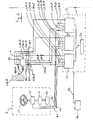
- control means 2 for imposing a steering of the vehicle.
- the control available to the driver of the vehicle can, as already said, take any suitable form. It may be a steering wheel 20, but it could also be any other control lever, such as a joystick, or a lever such as that described in the application.
- GB Patent 2,314,910 There is no mechanical connection between the steering wheel 20 and the steering wheel (s).
- Three sensors 21, 22 and 23 measure the steering wheel angle imposed by the driver. Each of the sensors 21, 22, 23 is part of a different electrical path and delivers one of said electrical signals carrying the information as to the requested path change.
- the specially designed electric actuator 3A which could have other uses (for example, it could be used in another electrical steering system), therefore comprises at least three electric motors acting in parallel (for engines, see references 31, 32 and 33 and the description of FIGS.
- each electric motor having its own electrical connection 661 (respectively 662, 663) independent of that of the other electric motors, intended to connect the motor to a specific controller , different from the controller controlling the other motors of the same actuator, as will appear below.
- a central unit 6 makes it possible to control the steering of the steering wheel or wheels.
- the number of steering wheels is arbitrary.
- the beams connecting the central unit 6 have not been represented to other groups, also not shown, comprising a steering wheel and its actuator.
- each actuator 3 is electrically connected to the central unit 6 by three completely independent beams or cables (one per control channel), whose paths are as separated as possible.
- the steering system according to the invention is such that each controller controls one of the electric motors of the actuator of each of the steering wheels, each controller making it possible to impose selectively an appropriate steering angle to each of the steered wheels based at least on the location of said steer wheel on the vehicle, the vehicle speed and the requested change or course correction.
- the number of steering wheels is arbitrary.
- the steering axle comprises two groups of members, each group comprising a steering wheel and an actuator.
- the steering axle may comprise a mechanical connection between steering wheels, of the rack and pinion type, and the sliding thereof is controlled by a single actuator 3. More generally, it is possible to implant any number of such groups. organs.
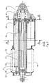
- each actuator 3 comprises a housing 40 used as a mechanical reference, a rod 41 moved linearly with respect to the reference end.
- the rod 41 is movable relative to the housing 40.
- the three electric motors 31, 32 and 33 act in parallel on a rotating screw 53.
- the rotational movement of the screw 53 is transformed into a linear displacement of the rod 41 as will be seen in more detail below.
- Each of the motors is sized to be able to transmit all alone the necessary torque, for reasons of operational safety. However, during operation in normal mode, the necessary torque is distributed between each of the three electric motors, which is a guarantee of longevity by reducing the stresses and the heating of each electric motor. This contributes to the reliability of the electric actuator.
- the rotary motion of electric motors is converted into linear motion by a screw / nut system.
- Each of the output shafts 310, 320 and 330 of the motors Electrical 31, 32 and 33 comprises a pinion 311, 321 and 331 geared on a toothed wheel 52.
- a sleeve 56 surrounds the rod 41. The end of the sleeve 56 forms a bearing guiding the sliding of the rod 41.
- the gear 52 is keyed on a tree.
- the shaft comprises on one side a screw 53.
- the shaft is mounted on a bearing 51 on one side, and on a bearing integrated in the rod 41 on the other side.
- the outer race of the bearing 51 is integral with the casing 40 of the electric actuator.
- a nut 54 is engaged with the screw 53.
- the sleeve 56 is integral with the casing 40.
- a protective bellows 30 is mounted on one side on the casing 40 of the motor and on the other on the rod 41.
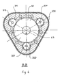
- each of the pinions 311, 321 and 331 is mounted in a star around the toothed wheel 52, with a constant offset of 120 ° relative to each other.
- This is of course only a non-limiting constructive provision.
- the rod 41 has a protuberance 410 which is itself engaged in a slot 560 dug in the sheath 56. In this way, the rod 41 is immobilized in rotation about its axis. Thus, the rotational movement of the screw 53 is converted into linear displacement by the nut 54 which moves along the screw 53.
- FIG. 2 and FIG. 3 show position sensors 71, 72 and 73 used to identify the displacement of the control end, that is to say of the rod 41, with respect to the reference end.
- the body 710 of the position sensor 71 is integral with the sleeve 56, and therefore with the casing 40 of the actuator 3.
- a slider 711 is integral with the rod 41, thus mobile with it.
- Two position sensors similar to the position sensor 71, namely the position sensors 72 and 73, are integrated in the same component 74. Each of the position sensors 71, 72, 73 is part of a different electrical path.
- the central unit 6 comprises three controllers 61, 62 and 63 (see FIG. 1) operating in parallel and simultaneously in normal operating mode, and in a manner that will appear subsequently in degraded operating mode (ie when a failure occurs, which of course the system can signal for example by activating a malfunction alert).
- Each of the controllers 61, 62 and 63 is part of an electrical channel for controlling the steering angle of a steering wheel.
- Each steering wheel is controlled by three electrical control channels.
- each controller 61 (or respectively 62 or 63) controls the steering angles of all the steered wheels.
- Each controller 61 (or respectively 62 or 63) acquires the information from one of the steering wheel angle sensors 21 (or respectively 22 or 23), by the electrical line S1 (or respectively S2 or S3). Furthermore, each controller 61 (or respectively 62 or 63) drives a motor 31 (or respectively 32 or 33) of each electric actuator 3 for each steering wheel by the line L1 (respectively L2 or L3) and receives position information. of the electric actuator 3 (that is to say in practice information on steering wheel) from a position sensor 71 (or respectively 72 or 73) for each of the steering wheels 1, by the electrical line C1 (or respectively C2 or C3). In addition, each controller 61 (or respectively 62 or 63) acquires for each of the steering wheels information from a current sensor of the electric motor with which it is associated in each of the electric actuators.
- each controller 61 (or respectively 62 or 63) provides control of all the steering wheels and each of the steering wheels is itself placed under the control of three independent controllers acting in parallel.
- the controllers themselves are different, for example of different types and / or different brands, in order to perfect the redundancy.
- the controllers are loaded with different software (different instruction sets, different writing languages, different programmers ) even if these software, different, all have the same purpose.
- each of these software having its own clean writing, however, leads to identical actions on the engines.
- Such redundancy, software limits the risk of occurrence of a malfunction (bug) in a combination of untested parameters.
- the three controllers 61, 62 and 63 are connected by at least one bus 8 and exchange in real time all the useful data to describe the electrical and mechanical state of each control channel.
- the operation of the electrical steering system remains in normal mode as long as all the similar parameters of each of the control channels have identical values, within tolerances. For example, as long as the steering wheel angle sensors 21, 22 and 23 deliver identical signals (within tolerances) on the lines S1, S2 and S3, it can be concluded that they all function correctly. As long as the electric currents on each of the lines L1, L2 and L3 connecting the three controllers 61, respectively 62 and 63, to the three electric motors 31, respectively 32 and 33, of each actuator 3 have identical values (within the tolerances), it can be concluded that all electric motors are working properly.
- the central unit 6 includes a backup battery 91 which automatically takes over from the main battery 90 of the vehicle in the event of its failure or in the event of a failure of the power supply line 92 between the battery main 90 and the control unit 6, to provide power backup of the electrical steering system in case of failure of normal power, while sending an appropriate alert.
- the auxiliary battery is recharged or maintained at its maximum state of charge by withdrawing energy from the main battery 90.
- the backup battery 91 is dimensioned so as to store a sufficient amount of energy to allow the battery to be charged.
- Each of the controllers 61, 62 and 63 includes a backup power supply from the backup battery with separate and protected individual circuits.
- the steering control may be a steering wheel or a joystick or other suitable device.
- this electric steering system goes very well with automatic stability control systems of the vehicle trajectory.
- the steering angle imposed on each of the steered wheels is determined not only by the control means on which the driver of the vehicle acts, but in addition, takes into account instructions for corrections from a control system.
- vehicle stability which decides to add or subtract a steering angle from the pilot's wish in order to maintain the vehicle's trajectory under safe conditions.
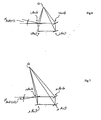
- FIG. 6 and 7 illustrate an application to a four-wheel steering system.
- An electric steering can very easily adapt to the longitudinal speed of movement of the vehicle. In maneuver at very low speed, to promote the mobility of the vehicle, it is useful to steer the rear wheels in the opposite direction of the front wheels as shown in Figure 6.
- the vehicle turns left, and it was noted in particular the steering angle of the left rear wheel ⁇ ArG (v1) at the speed v1.
- v1 the steering angle of the left rear wheel ⁇ ArG (v1) at the speed v1.
- FIG. 7 where the vehicle is still turning to the left, and in particular the steering angle of the left rear wheel ⁇ ArG (v2) at speed v2 (values d angle not representative of a real situation).
- selectively controlling wheel-by-wheel steering angle can, from the steering angle imposed by the driver of the vehicle and the longitudinal speed of movement of the vehicle, determine the instantaneous center of rotation. ideal for the vehicle.
- This instantaneous center of rotation is identified by the point Q in FIGS. 6 and 7.
- this instantaneous center of rotation is chosen, by connecting it to the center of each of the steering wheels, it is possible to calculate the steering angle of each of the wheels so that the plane of the wheel is perpendicular to the line connecting the center of the wheel considered instantaneous center of rotation of the vehicle Q.
- the vehicle revolves around the instantaneous center of rotation of the vehicle Q.
- the instantaneous center of rotation of the vehicle Q is continuously calculated dynamically, according to the driving conditions (vehicle speed, yaw rate, ).
Landscapes
- Engineering & Computer Science (AREA)
- Chemical & Material Sciences (AREA)
- Combustion & Propulsion (AREA)
- Transportation (AREA)
- Mechanical Engineering (AREA)
- Power Engineering (AREA)
- Steering Control In Accordance With Driving Conditions (AREA)
- Power Steering Mechanism (AREA)
- Steering-Linkage Mechanisms And Four-Wheel Steering (AREA)
- Connection Of Motors, Electrical Generators, Mechanical Devices, And The Like (AREA)
- Air Bags (AREA)
Applications Claiming Priority (2)
| Application Number | Priority Date | Filing Date | Title |
|---|---|---|---|
| FR0115221 | 2001-11-23 | ||
| FR0115221A FR2832685A1 (fr) | 2001-11-23 | 2001-11-23 | Direction electrique pour vehicule, a redondance triple |
Publications (2)
| Publication Number | Publication Date |
|---|---|
| EP1314628A1 EP1314628A1 (fr) | 2003-05-28 |
| EP1314628B1 true EP1314628B1 (fr) | 2007-08-22 |
Family
ID=8869753
Family Applications (1)
| Application Number | Title | Priority Date | Filing Date |
|---|---|---|---|
| EP02025478A Expired - Lifetime EP1314628B1 (fr) | 2001-11-23 | 2002-11-15 | Direction électrique pour véhicule, à redondance triple |
Country Status (8)
Families Citing this family (44)
| Publication number | Priority date | Publication date | Assignee | Title |
|---|---|---|---|---|
| JP3847702B2 (ja) | 2002-12-02 | 2006-11-22 | 株式会社ジェイテクト | 車両の操舵制御装置 |
| JP2004291877A (ja) * | 2003-03-27 | 2004-10-21 | Toyoda Mach Works Ltd | 車両用操舵装置 |
| DE10352495A1 (de) * | 2003-11-11 | 2005-06-09 | Robert Bosch Gmbh | Verfahren zum Ansteuern einer Kupplungseinheit |
| US7190096B2 (en) * | 2004-06-04 | 2007-03-13 | The Boeing Company | Fault-tolerant electro-mechanical actuator having motor armatures to drive a ram and having an armature release mechanism |
| DE102004034126A1 (de) * | 2004-07-15 | 2006-02-02 | GM Global Technology Operations, Inc., Detroit | Straßenfahrzeug mit Steer-by-Wire-System |
| JP4506956B2 (ja) * | 2004-07-20 | 2010-07-21 | 株式会社ジェイテクト | ステアバイワイヤシステム |
| US20060042858A1 (en) * | 2004-08-24 | 2006-03-02 | Trw Automotive U.S. Llc | Steer-by-wire steering apparatus with redundant electric motor drive systems |
| FR2883828B1 (fr) * | 2005-04-01 | 2007-05-25 | Conception & Dev Michelin Sa | Commande de direction de vehicule sans liaison mecanique entre volant et roues directrices |
| FR2883827B1 (fr) * | 2005-04-01 | 2007-05-18 | Conception & Dev Michelin Sa | Commande de direction de vehicule sans liaison mecanique entre volant et roues directrices |
| JP2006321271A (ja) | 2005-05-17 | 2006-11-30 | Jtekt Corp | 車両用操舵装置 |
| JP4874639B2 (ja) * | 2005-12-12 | 2012-02-15 | 株式会社東芝 | 放射線モニタ装置 |
| GB0604131D0 (en) * | 2006-03-01 | 2006-04-12 | Airbus Uk Ltd | Jam-tolerant actuator |
| FR2898706B1 (fr) * | 2006-03-17 | 2008-06-13 | Alstom Transport Sa | Dispositif de commande securise a diversification d'un systeme ferroviaire |
| WO2007107576A1 (fr) * | 2006-03-23 | 2007-09-27 | Michelin Recherche Et Technique S.A. | Système de freinage électrique d'un véhicule routier, à contrôle totalement électrique |
| GB0616730D0 (en) * | 2006-08-23 | 2006-10-04 | Airbus Uk Ltd | Jam-tolerant actuator |
| CN100440079C (zh) * | 2007-01-16 | 2008-12-03 | 北京航空航天大学 | 直接驱动式三余度无刷直流力矩电机有限转角驱动控制器 |
| US7634340B2 (en) * | 2007-02-27 | 2009-12-15 | Gm Global Technology Operations, Inc. | Secure control mode transition methods for an active front steer system |
| KR101037250B1 (ko) * | 2007-05-30 | 2011-05-26 | 미쓰비시덴키 가부시키가이샤 | 차량용 조타 장치 |
| JP4623063B2 (ja) * | 2007-08-02 | 2011-02-02 | 株式会社デンソー | 操舵補助装置 |
| JP4900167B2 (ja) | 2007-09-27 | 2012-03-21 | 株式会社デンソー | 車両用操舵装置 |
| US8060278B2 (en) * | 2007-10-15 | 2011-11-15 | GM Global Technology Operations LLC | Methods and systems for controlling steering in a vehicle using a primary active steering functionality and a supplemental active steering functionality |
| DE102008000365A1 (de) * | 2008-02-21 | 2009-08-27 | Zf Friedrichshafen Ag | Steer by Wire Lenkung für ein Kraftfahrzeug |
| US8070094B2 (en) * | 2008-07-16 | 2011-12-06 | Hamilton Sundstrand Corporation | Aircraft landing gear actuator |
| NL1037274C2 (nl) * | 2009-09-11 | 2011-03-14 | Advanced Public Transp Systems B V | Stuurinrichting voor een vooraf gedefinieerd traject verplaatsbaar voertuig, automatisch gestuurd en via tenminste een eerste as , alsmede een voertuig voorzien van een dergelijke stuurinrichting. |
| NL1037276C2 (nl) * | 2009-09-11 | 2011-03-14 | Advanced Public Transp Systems B V | Stuurinrichting voor een via tenminste een eerste as automatisch gestuurd en tijdens bedrijf langs een vooraf gedefinieerd traject verplaatsbaar voertuig, alsmede een voertuig voorzien van een dergelijke stuurinrichting. |
| US8840507B2 (en) * | 2009-10-05 | 2014-09-23 | Hamilton Sunstrand Corporation | Dual redundant linear EMA with hard stop compliant driveline |
| GB2475888A (en) * | 2009-12-04 | 2011-06-08 | Meritor Heavy Vehicle Sys Ltd | Differential lock actuator |
| DE102014201450A1 (de) * | 2013-02-21 | 2014-08-21 | Ford Global Technologies, Llc | Kraftfahrzeug-Lenkvorrichtung und Verfahren zum Erfassen eines Lenkmoments |
| DE102014012006A1 (de) * | 2014-08-12 | 2016-02-18 | Liebherr-Werk Bischofshofen Gmbh | Fahrzeugsteuerung für eine mobile Arbeitsmaschine |
| DE102015203411A1 (de) | 2015-02-26 | 2016-09-01 | Zf Friedrichshafen Ag | Aktuator für Luftfahrtanwendungen |
| US10167015B2 (en) * | 2015-05-11 | 2019-01-01 | GM Global Technology Operations LLC | System for retrofitting vehicle automation |
| CN104991477B (zh) * | 2015-07-24 | 2018-02-13 | 厦门理工学院 | 一种载人平衡车控制方法及一种载人平衡车 |
| FR3042329B1 (fr) | 2015-10-12 | 2018-04-20 | Whylot | Direction assistee de vehicule automobile avec un moteur electromagnetique a flux magnetique axial |
| JP6535572B2 (ja) * | 2015-10-26 | 2019-06-26 | 日立オートモティブシステムズ株式会社 | 車両制御装置、車両制御システム |
| CN106020078B (zh) * | 2016-05-20 | 2018-08-28 | 清华大学 | 一种用于双余度转向机的余度控制器电路 |
| CN107499374B (zh) * | 2017-07-10 | 2019-04-02 | 清华大学 | 一种双余度线传转向系统 |
| EP3652037B1 (en) * | 2017-07-13 | 2023-09-13 | Danfoss Power Solutions II Technology A/S | Electromechanical controller |
| US10752282B2 (en) * | 2017-10-04 | 2020-08-25 | Steering Solutions Ip Holding Corporation | Triple redundancy failsafe for steering systems |
| KR20190045468A (ko) * | 2017-10-24 | 2019-05-03 | 주식회사 만도 | 세이프티 향상을 위해 센서의 신호 개수를 증가한 전동식 조향 장치 |
| DE102017219816B4 (de) * | 2017-11-08 | 2022-12-08 | Volkswagen Aktiengesellschaft | Elektromechanisches Lenkantriebssystem zum Bereitstellen einer Lenkunterstützung für ein Lenksystem |
| JP7061055B2 (ja) * | 2018-11-06 | 2022-04-27 | 日立Astemo株式会社 | ステアリング装置 |
| WO2021213618A1 (en) * | 2020-04-20 | 2021-10-28 | Thyssenkrupp Presta Ag | Degradation concept for a steer-by-wire steering system |
| JP7200976B2 (ja) * | 2020-05-12 | 2023-01-10 | 株式会社デンソー | ステアリング制御装置 |
| JP7549746B2 (ja) * | 2021-07-09 | 2024-09-11 | 日立Astemo株式会社 | 電動パワーステアリング装置、電動パワーステアリング装置の制御方法及び操舵制御装置 |
Family Cites Families (22)
| Publication number | Priority date | Publication date | Assignee | Title |
|---|---|---|---|---|
| US3679956A (en) * | 1970-02-02 | 1972-07-25 | Ltv Electrosystems Inc | Multiple servomotor actuator |
| US3735228A (en) * | 1972-01-03 | 1973-05-22 | E Systems Inc | Non-electronic servo actuator |
| US4179944A (en) * | 1977-06-27 | 1979-12-25 | United Technologies Corporation | Fail safe redundant actuator |
| US4215592A (en) * | 1978-08-04 | 1980-08-05 | The United States Of America As Represented By The Administrator Of The National Aeronautics And Space Administration | Redundant motor drive system |
| US4304375A (en) * | 1979-05-17 | 1981-12-08 | Textron Inc. | Electrically controlled elevator |
| ATE19543T1 (de) * | 1981-12-18 | 1986-05-15 | Lars Int Sa | Linear-antriebsvorrichtung mit zwei motoren. |
| US4521707A (en) * | 1983-12-12 | 1985-06-04 | The Boeing Company | Triple redundant electromechanical linear actuator and method |
| US4637272A (en) * | 1985-10-28 | 1987-01-20 | Sundstrand Corporation | Ballscrew actuator |
| US4834319A (en) * | 1987-10-05 | 1989-05-30 | Allied-Signal Inc. | Differentially coupled dual channel actuator |
| US4858491A (en) * | 1988-01-21 | 1989-08-22 | Plessey Incorporated | Fail-free actuator assembly |
| JPH04133861A (ja) * | 1990-09-25 | 1992-05-07 | Honda Motor Co Ltd | 車輌用操舵装置の制御方法 |
| US5152381A (en) * | 1991-09-30 | 1992-10-06 | Rockwell International Corporation | Multiple fail operational rotary actuator with series mounted motor stages |
| JPH0662508A (ja) * | 1992-08-05 | 1994-03-04 | Nissan Motor Co Ltd | 電気自動車の動力制御方法および制御装置 |
| US5670856A (en) * | 1994-11-07 | 1997-09-23 | Alliedsignal Inc. | Fault tolerant controller arrangement for electric motor driven apparatus |
| DE19625500C2 (de) | 1996-06-26 | 1999-10-14 | Daimler Chrysler Ag | Bedienelementanordnung zur Steuerung der Längs- und der Querbewegung eines Kraftfahrzeuges |
| JP3577190B2 (ja) * | 1997-03-19 | 2004-10-13 | トヨタ自動車株式会社 | 操舵制御装置 |
| DE19941474A1 (de) * | 1999-09-01 | 2001-03-15 | Bosch Gmbh Robert | Elektromotorischer Antrieb, insbesondere für automatische Schaltgetriebe in Nutzkraftwagen |
| DE29915559U1 (de) * | 1999-09-03 | 2000-01-13 | TRW Fahrwerksysteme GmbH & Co KG, 40547 Düsseldorf | Lenksystem für ein Fahrzeug |
| DE19946073A1 (de) * | 1999-09-25 | 2001-05-10 | Volkswagen Ag | System zur Steuerung von Fahrzeugkomponenten nach dem "Drive By Wire"-Prinzip |
| FR2804647B1 (fr) * | 2000-02-04 | 2002-06-07 | Renault Vehicules Ind | Dispositif de servodirection de vehicule automobile |
| US6548969B2 (en) * | 2000-12-29 | 2003-04-15 | Delphi Technologies, Inc. | Redundant steer-by-wire system |
| US6913106B2 (en) * | 2002-08-30 | 2005-07-05 | Nissan Motor Co., Ltd. | Vehicle steering system |
-
2001
- 2001-11-23 FR FR0115221A patent/FR2832685A1/fr active Pending
-
2002
- 2002-11-15 DE DE60221949T patent/DE60221949T2/de not_active Expired - Lifetime
- 2002-11-15 EP EP02025478A patent/EP1314628B1/fr not_active Expired - Lifetime
- 2002-11-15 ES ES02025478T patent/ES2291411T3/es not_active Expired - Lifetime
- 2002-11-15 AT AT02025478T patent/ATE370876T1/de not_active IP Right Cessation
- 2002-11-21 US US10/301,083 patent/US6820715B2/en not_active Expired - Lifetime
- 2002-11-22 CN CNB021488940A patent/CN1286690C/zh not_active Expired - Fee Related
- 2002-11-22 CN CN2006101063056A patent/CN1966331B/zh not_active Expired - Fee Related
- 2002-11-25 JP JP2002340229A patent/JP4263902B2/ja not_active Expired - Fee Related
-
2007
- 2007-02-15 JP JP2007034779A patent/JP4355728B2/ja not_active Expired - Fee Related
Also Published As
| Publication number | Publication date |
|---|---|
| EP1314628A1 (fr) | 2003-05-28 |
| ATE370876T1 (de) | 2007-09-15 |
| US6820715B2 (en) | 2004-11-23 |
| JP4263902B2 (ja) | 2009-05-13 |
| DE60221949T2 (de) | 2008-05-15 |
| ES2291411T3 (es) | 2008-03-01 |
| US20030098197A1 (en) | 2003-05-29 |
| JP4355728B2 (ja) | 2009-11-04 |
| DE60221949D1 (de) | 2007-10-04 |
| JP2007210607A (ja) | 2007-08-23 |
| CN1966331A (zh) | 2007-05-23 |
| CN1966331B (zh) | 2010-12-15 |
| JP2003200840A (ja) | 2003-07-15 |
| FR2832685A1 (fr) | 2003-05-30 |
| CN1426920A (zh) | 2003-07-02 |
| CN1286690C (zh) | 2006-11-29 |
Similar Documents
| Publication | Publication Date | Title |
|---|---|---|
| EP1314628B1 (fr) | Direction électrique pour véhicule, à redondance triple | |
| EP1428740B1 (fr) | Système de direction d'un véhicule comportant un mode de fonctionnement dégradé en cas de panne d'un actionneur de braquage de roue | |
| EP1904359B1 (fr) | Systeme de direction d'un véhicule comportant un mode de fonctionnement dégradé en cas de panne d'un actionneur de braquage de roue | |
| RU2715963C1 (ru) | Система рулевого управления | |
| EP1899212B1 (fr) | Commande de direction de véhicule sans liaison mécanique entre volant et roues directrices | |
| US8423257B2 (en) | System for and method of maintaining a driver intended path | |
| EP1883569B1 (fr) | Commande de direction de vehicule sans liaison mecanique entre volant et roues directrices | |
| EP2070818B1 (fr) | Procédé d'alimentation en énergie d'actionneurs associés à un train d'atterrissage d'aéronef | |
| US11459021B2 (en) | Steer-by-wire steering system with a feedback actuator having redundant sleep-mode rotor position sensors | |
| FR2819474A1 (fr) | Dispositif de direction pour vehicules | |
| FR2952448A1 (fr) | Dispositif de controle electronique d'un organe de pilotage a microcontroleurs multifonctionnels, dispositif de pilotage et aeronef | |
| FR2952447A1 (fr) | Dispositif de controle electronique de fonctionnement d'un organe de pilotage a surveillance croisee, dispositif de pilotage et aeronef | |
| EP0371851B1 (fr) | Dispositif auxiliaire du traitement des défaillances d'un système d'actionnement d'un vérin électrique linéaire | |
| JP4382345B2 (ja) | 車両用操舵装置 | |
| FR2914260A1 (fr) | Vehicule motorise comprenant une unite de controle du vehicule se trouvant en situation de virage et procede correspondant. | |
| FR2846645A1 (fr) | Procede et dispositif de guidage d'un chariot de manutention | |
| JPH0487881A (ja) | 電動パワーステアリング装置 | |
| WO2008049979A1 (fr) | Système de direction assurant la commande de l'angle de braquage des roues directrices d'un véhicule | |
| FR3151567A1 (fr) | Architecture de direction assistée sans liaison mécanique entre le volant de direction et le mécanisme de direction du véhicule | |
| US8640817B2 (en) | Steering apparatus for turning multiple sets of steerable vehicle wheels | |
| FR2814136A1 (fr) | Servodirection | |
| FR3048218A1 (fr) | Architecture electromecanique de vehicule automobile | |
| EP1234747A1 (fr) | Ensemble de direction assistée électrique pour véhicule et procédé de commande associé | |
| WO2004071846A1 (fr) | Procede de commande de la direction d'un vehicule automobile | |
| FR2903366A1 (fr) | Vehicule sans liaison mecanique entre l'organe de direction et les roues directrices et muni d'actionneurs de commande |
Legal Events
| Date | Code | Title | Description |
|---|---|---|---|
| PUAI | Public reference made under article 153(3) epc to a published international application that has entered the european phase |
Free format text: ORIGINAL CODE: 0009012 |
|
| AK | Designated contracting states |
Designated state(s): AT BE BG CH CY CZ DE DK EE ES FI FR GB GR IE IT LI LU MC NL PT SE SK TR |
|
| AX | Request for extension of the european patent |
Extension state: AL LT LV MK RO SI |
|
| 17P | Request for examination filed |
Effective date: 20031128 |
|
| AKX | Designation fees paid |
Designated state(s): AT BE BG CH CY CZ DE DK EE ES FI FR GB GR IE IT LI LU MC NL PT SE SK TR |
|
| GRAP | Despatch of communication of intention to grant a patent |
Free format text: ORIGINAL CODE: EPIDOSNIGR1 |
|
| GRAS | Grant fee paid |
Free format text: ORIGINAL CODE: EPIDOSNIGR3 |
|
| RAP1 | Party data changed (applicant data changed or rights of an application transferred) |
Owner name: MICHELIN RECHERCHE ET TECHNIQUE S.A. |
|
| GRAA | (expected) grant |
Free format text: ORIGINAL CODE: 0009210 |
|
| AK | Designated contracting states |
Kind code of ref document: B1 Designated state(s): AT BE BG CH CY CZ DE DK EE ES FI FR GB GR IE IT LI LU MC NL PT SE SK TR |
|
| REG | Reference to a national code |
Ref country code: GB Ref legal event code: FG4D Free format text: NOT ENGLISH |
|
| REG | Reference to a national code |
Ref country code: CH Ref legal event code: EP |
|
| REG | Reference to a national code |
Ref country code: IE Ref legal event code: FG4D Free format text: LANGUAGE OF EP DOCUMENT: FRENCH |
|
| REF | Corresponds to: |
Ref document number: 60221949 Country of ref document: DE Date of ref document: 20071004 Kind code of ref document: P |
|
| GBT | Gb: translation of ep patent filed (gb section 77(6)(a)/1977) |
Effective date: 20071107 |
|
| PG25 | Lapsed in a contracting state [announced via postgrant information from national office to epo] |
Ref country code: NL Free format text: LAPSE BECAUSE OF FAILURE TO SUBMIT A TRANSLATION OF THE DESCRIPTION OR TO PAY THE FEE WITHIN THE PRESCRIBED TIME-LIMIT Effective date: 20070822 Ref country code: BG Free format text: LAPSE BECAUSE OF FAILURE TO SUBMIT A TRANSLATION OF THE DESCRIPTION OR TO PAY THE FEE WITHIN THE PRESCRIBED TIME-LIMIT Effective date: 20071122 Ref country code: FI Free format text: LAPSE BECAUSE OF FAILURE TO SUBMIT A TRANSLATION OF THE DESCRIPTION OR TO PAY THE FEE WITHIN THE PRESCRIBED TIME-LIMIT Effective date: 20070822 |
|
| NLV1 | Nl: lapsed or annulled due to failure to fulfill the requirements of art. 29p and 29m of the patents act | ||
| PG25 | Lapsed in a contracting state [announced via postgrant information from national office to epo] |
Ref country code: AT Free format text: LAPSE BECAUSE OF FAILURE TO SUBMIT A TRANSLATION OF THE DESCRIPTION OR TO PAY THE FEE WITHIN THE PRESCRIBED TIME-LIMIT Effective date: 20070822 |
|
| REG | Reference to a national code |
Ref country code: ES Ref legal event code: FG2A Ref document number: 2291411 Country of ref document: ES Kind code of ref document: T3 |
|
| REG | Reference to a national code |
Ref country code: IE Ref legal event code: FD4D |
|
| PG25 | Lapsed in a contracting state [announced via postgrant information from national office to epo] |
Ref country code: GR Free format text: LAPSE BECAUSE OF FAILURE TO SUBMIT A TRANSLATION OF THE DESCRIPTION OR TO PAY THE FEE WITHIN THE PRESCRIBED TIME-LIMIT Effective date: 20071123 Ref country code: DK Free format text: LAPSE BECAUSE OF FAILURE TO SUBMIT A TRANSLATION OF THE DESCRIPTION OR TO PAY THE FEE WITHIN THE PRESCRIBED TIME-LIMIT Effective date: 20070822 |
|
| PG25 | Lapsed in a contracting state [announced via postgrant information from national office to epo] |
Ref country code: CZ Free format text: LAPSE BECAUSE OF FAILURE TO SUBMIT A TRANSLATION OF THE DESCRIPTION OR TO PAY THE FEE WITHIN THE PRESCRIBED TIME-LIMIT Effective date: 20070822 Ref country code: SK Free format text: LAPSE BECAUSE OF FAILURE TO SUBMIT A TRANSLATION OF THE DESCRIPTION OR TO PAY THE FEE WITHIN THE PRESCRIBED TIME-LIMIT Effective date: 20070822 Ref country code: PT Free format text: LAPSE BECAUSE OF FAILURE TO SUBMIT A TRANSLATION OF THE DESCRIPTION OR TO PAY THE FEE WITHIN THE PRESCRIBED TIME-LIMIT Effective date: 20080122 Ref country code: IE Free format text: LAPSE BECAUSE OF FAILURE TO SUBMIT A TRANSLATION OF THE DESCRIPTION OR TO PAY THE FEE WITHIN THE PRESCRIBED TIME-LIMIT Effective date: 20070822 |
|
| BERE | Be: lapsed |
Owner name: MICHELIN RECHERCHE ET TECHNIQUE S.A. Effective date: 20071130 |
|
| PLBE | No opposition filed within time limit |
Free format text: ORIGINAL CODE: 0009261 |
|
| STAA | Information on the status of an ep patent application or granted ep patent |
Free format text: STATUS: NO OPPOSITION FILED WITHIN TIME LIMIT |
|
| PG25 | Lapsed in a contracting state [announced via postgrant information from national office to epo] |
Ref country code: MC Free format text: LAPSE BECAUSE OF NON-PAYMENT OF DUE FEES Effective date: 20071130 Ref country code: SE Free format text: LAPSE BECAUSE OF FAILURE TO SUBMIT A TRANSLATION OF THE DESCRIPTION OR TO PAY THE FEE WITHIN THE PRESCRIBED TIME-LIMIT Effective date: 20071122 |
|
| 26N | No opposition filed |
Effective date: 20080526 |
|
| PG25 | Lapsed in a contracting state [announced via postgrant information from national office to epo] |
Ref country code: BE Free format text: LAPSE BECAUSE OF NON-PAYMENT OF DUE FEES Effective date: 20071130 |
|
| PG25 | Lapsed in a contracting state [announced via postgrant information from national office to epo] |
Ref country code: EE Free format text: LAPSE BECAUSE OF FAILURE TO SUBMIT A TRANSLATION OF THE DESCRIPTION OR TO PAY THE FEE WITHIN THE PRESCRIBED TIME-LIMIT Effective date: 20070822 |
|
| PG25 | Lapsed in a contracting state [announced via postgrant information from national office to epo] |
Ref country code: CY Free format text: LAPSE BECAUSE OF FAILURE TO SUBMIT A TRANSLATION OF THE DESCRIPTION OR TO PAY THE FEE WITHIN THE PRESCRIBED TIME-LIMIT Effective date: 20070822 |
|
| PG25 | Lapsed in a contracting state [announced via postgrant information from national office to epo] |
Ref country code: LU Free format text: LAPSE BECAUSE OF NON-PAYMENT OF DUE FEES Effective date: 20071115 |
|
| PGFP | Annual fee paid to national office [announced via postgrant information from national office to epo] |
Ref country code: TR Payment date: 20091023 Year of fee payment: 8 |
|
| PG25 | Lapsed in a contracting state [announced via postgrant information from national office to epo] |
Ref country code: TR Free format text: LAPSE BECAUSE OF NON-PAYMENT OF DUE FEES Effective date: 20101115 |
|
| REG | Reference to a national code |
Ref country code: FR Ref legal event code: PLFP Year of fee payment: 14 |
|
| PGFP | Annual fee paid to national office [announced via postgrant information from national office to epo] |
Ref country code: GB Payment date: 20151118 Year of fee payment: 14 Ref country code: CH Payment date: 20151118 Year of fee payment: 14 Ref country code: IT Payment date: 20151125 Year of fee payment: 14 |
|
| PGFP | Annual fee paid to national office [announced via postgrant information from national office to epo] |
Ref country code: FR Payment date: 20151119 Year of fee payment: 14 Ref country code: ES Payment date: 20151111 Year of fee payment: 14 |
|
| PGFP | Annual fee paid to national office [announced via postgrant information from national office to epo] |
Ref country code: DE Payment date: 20161121 Year of fee payment: 15 |
|
| REG | Reference to a national code |
Ref country code: CH Ref legal event code: PL |
|
| GBPC | Gb: european patent ceased through non-payment of renewal fee |
Effective date: 20161115 |
|
| PG25 | Lapsed in a contracting state [announced via postgrant information from national office to epo] |
Ref country code: CH Free format text: LAPSE BECAUSE OF NON-PAYMENT OF DUE FEES Effective date: 20161130 Ref country code: LI Free format text: LAPSE BECAUSE OF NON-PAYMENT OF DUE FEES Effective date: 20161130 |
|
| REG | Reference to a national code |
Ref country code: FR Ref legal event code: ST Effective date: 20170731 |
|
| PG25 | Lapsed in a contracting state [announced via postgrant information from national office to epo] |
Ref country code: FR Free format text: LAPSE BECAUSE OF NON-PAYMENT OF DUE FEES Effective date: 20161130 Ref country code: IT Free format text: LAPSE BECAUSE OF NON-PAYMENT OF DUE FEES Effective date: 20161115 |
|
| PG25 | Lapsed in a contracting state [announced via postgrant information from national office to epo] |
Ref country code: GB Free format text: LAPSE BECAUSE OF NON-PAYMENT OF DUE FEES Effective date: 20161115 |
|
| PG25 | Lapsed in a contracting state [announced via postgrant information from national office to epo] |
Ref country code: ES Free format text: LAPSE BECAUSE OF FAILURE TO SUBMIT A TRANSLATION OF THE DESCRIPTION OR TO PAY THE FEE WITHIN THE PRESCRIBED TIME-LIMIT Effective date: 20070822 |
|
| REG | Reference to a national code |
Ref country code: DE Ref legal event code: R119 Ref document number: 60221949 Country of ref document: DE |
|
| PG25 | Lapsed in a contracting state [announced via postgrant information from national office to epo] |
Ref country code: DE Free format text: LAPSE BECAUSE OF NON-PAYMENT OF DUE FEES Effective date: 20180602 |
|
| REG | Reference to a national code |
Ref country code: ES Ref legal event code: FD2A Effective date: 20181119 |
|
| PG25 | Lapsed in a contracting state [announced via postgrant information from national office to epo] |
Ref country code: ES Free format text: LAPSE BECAUSE OF FAILURE TO SUBMIT A TRANSLATION OF THE DESCRIPTION OR TO PAY THE FEE WITHIN THE PRESCRIBED TIME-LIMIT Effective date: 20161116 |