EP1314590A2 - Vehicle air conditioner that operates during engine stops - Google Patents
Vehicle air conditioner that operates during engine stops Download PDFInfo
- Publication number
- EP1314590A2 EP1314590A2 EP02026346A EP02026346A EP1314590A2 EP 1314590 A2 EP1314590 A2 EP 1314590A2 EP 02026346 A EP02026346 A EP 02026346A EP 02026346 A EP02026346 A EP 02026346A EP 1314590 A2 EP1314590 A2 EP 1314590A2
- Authority
- EP
- European Patent Office
- Prior art keywords
- thermal energy
- cold thermal
- energy storage
- air
- cold
- Prior art date
- Legal status (The legal status is an assumption and is not a legal conclusion. Google has not performed a legal analysis and makes no representation as to the accuracy of the status listed.)
- Granted
Links
Images


Classifications
-
- B—PERFORMING OPERATIONS; TRANSPORTING
- B60—VEHICLES IN GENERAL
- B60H—ARRANGEMENTS OF HEATING, COOLING, VENTILATING OR OTHER AIR-TREATING DEVICES SPECIALLY ADAPTED FOR PASSENGER OR GOODS SPACES OF VEHICLES
- B60H1/00—Heating, cooling or ventilating devices
- B60H1/00492—Heating, cooling or ventilating devices comprising regenerative heating or cooling means, e.g. heat accumulators
- B60H1/005—Regenerative cooling means, e.g. cold accumulators
-
- F—MECHANICAL ENGINEERING; LIGHTING; HEATING; WEAPONS; BLASTING
- F25—REFRIGERATION OR COOLING; COMBINED HEATING AND REFRIGERATION SYSTEMS; HEAT PUMP SYSTEMS; MANUFACTURE OR STORAGE OF ICE; LIQUEFACTION SOLIDIFICATION OF GASES
- F25B—REFRIGERATION MACHINES, PLANTS OR SYSTEMS; COMBINED HEATING AND REFRIGERATION SYSTEMS; HEAT PUMP SYSTEMS
- F25B2400/00—Component parts or details not otherwise provided for in this subclass
- F25B2400/24—Thermal storage element
-
- F—MECHANICAL ENGINEERING; LIGHTING; HEATING; WEAPONS; BLASTING
- F25—REFRIGERATION OR COOLING; COMBINED HEATING AND REFRIGERATION SYSTEMS; HEAT PUMP SYSTEMS; MANUFACTURE OR STORAGE OF ICE; LIQUEFACTION SOLIDIFICATION OF GASES
- F25D—REFRIGERATORS; COLD ROOMS; ICE-BOXES; COOLING OR FREEZING APPARATUS NOT OTHERWISE PROVIDED FOR
- F25D16/00—Devices using a combination of a cooling mode associated with refrigerating machinery with a cooling mode not associated with refrigerating machinery
Definitions
- the present invention relates to a cold thermal energy storage type vehicle air conditioner having a cold thermal energy storage unit cooled by cold air passed through a cooling evaporator, and the invention is applied to a vehicle whose vehicle engine, a driving source for a compressor is stopped when the vehicle stops moving.
- the compressor in the refrigeration cycle is driven by the vehicle engine, and therefore every time the above eco-run car stops moving, which stops the engine, the compressor also stops and the temperature in the cooling evaporator increases. This raises the temperature of air blown into the vehicle cabin, and reduces the comfort of the passengers as they cannot continue to feel cool enough because the increase in air temperature.
- the cold thermal energy storage unit will store cold thermal energy during the operation of the compressor, and can cool air blown into the cabin by the cold thermal energy storage unit when the compressor is stopped (when the cooling function by the cooling evaporator stops).
- the inventors are presently in the process of developing such a cold thermal energy storage type vehicle air conditioner. If the cold thermal energy quantity stored in the cold thermal energy storage unit is small while the vehicle runs, there is only a short supply time for cooling air to be blown into the cabin at a comfortably low temperature when the engine is stopped. Therefore, the stored cold thermal energy quantity while the vehicle runs, that is, while the engine operates, must be known.
- the invention is directed to a solution to the above problem. It is an object of the invention to provide a cold thermal energy storage type vehicle air conditioner that allows the quantity of cold thermal energy stored in the cold thermal energy storage unit during the operation of the vehicle engine to be accurately calculated. Another object of the invention is to provide a cold thermal energy storage type vehicle air conditioner that allows air conditioning control to be accurately carried out when the vehicle engine is stopped depending upon the stored quantity of cold thermal energy stored in the cold thermal energy storage unit.
- a cold thermal energy storage unit (40) provided on the downstream side of an evaporator (9) and cooled by cold air passed through the evaporator (9).
- the air blown into the cabin is cooled by a quantity of the stored cold thermal energy of the cold thermal energy storage unit (40) when the vehicle engine (4) is stopped.
- the cold thermal energy storage unit (40) has a cold thermal energy storage material (44) cooled and solidified by the cold air passed through the evaporator (9).
- the cold thermal energy storage time is measured. This is accomplished by measuring the time for the temperature of the cold thermal energy storage unit (40) to reach the solidifying point of the cold thermal energy storage material (44) or lower.
- the stored cold thermal energy quantity of the cold thermal energy storage material (44) during the operation of the vehicle engine (4) is calculated based on information including at least the cold thermal energy storage time and the volume of the cold air.
- cold thermal energy by latent heat is stored in response to the temperature of the cold thermal energy storage unit (40) reaching the solidifying temperature, or lower, of the cold thermal energy storage material (44). Therefore, the time after the temperature of the cold thermal energy storage unit (40) reaches the solidifying temperature, or lower, of the cold thermal energy storage material (44) and the volume of the cold air, are pieces of information most related to the cold thermal energy storage heat quantity of the cold thermal energy storage material (44).
- the stored cold thermal energy quantity of the cold thermal energy storage material (44) is calculated based on information including at least the time after the temperature of the cold thermal energy storage unit (40) reaches the solidifying point, or lower, of the cold thermal energy storage material (44), i.e., the cold thermal energy storage time and the volume of cold air. Therefore, stored cold thermal energy quantity of the cold thermal energy storage material during the operation of the vehicle engine (4) can accurately be calculated.
- the stored cold thermal energy quantity is calculated based on the cold thermal energy storage time, the volume of the cold air, the temperature of the evaporator (9), and the temperature of the cold thermal energy storage unit (40).
- the stored cold thermal energy quantity of the cold thermal energy storage material (44) corresponds to the temperature of air of the cold thermal energy storage unit (40) before and after cold thermal energy storage.
- the quantity corresponds to the temperature difference before and after cold thermal energy storage. Therefore, the temperature difference between them (9, 10) based on the temperatures of the evaporator (9) and the cold thermal energy storage unit (40) is taken into consideration in calculating the stored cold thermal energy quantity of the cold thermal energy storage material, and therefore the stored cold thermal energy quantity can more accurately be calculated.
- the cold thermal energy storage unit (40) in a vehicle air conditioner in which there is a cold thermal energy storage unit (40) provided on the air downstream side of an evaporator (9) and cooled by cold air passed through the evaporator (9), and air blown into the cabin is cooled by the stored cold thermal energy quantity of the cold thermal energy storage unit (40) when the vehicle engine (4) is stopped, the cold thermal energy storage unit (40) has a cold thermal energy storage material (44) cooled and solidified by the cold air passed through the evaporator (9).
- the cold thermal energy storage completion time after the temperature of the cold thermal energy storage unit (40) reaches the solidifying point, or lower, of the cold thermal energy storage material (44), that is, until cold thermal energy storage to the cold thermal energy storage material (44) is completed, is pre-set for each air volume of cold air.
- the time passed, after the temperature of the cold thermal energy storage unit (40) reaches the solidifying point, or lower, of the cold thermal energy storage material (44), is measured.
- the pre-set cold thermal energy storage completion time is selected based on the actual cold air volume after the temperature of the cold thermal energy storage unit (40) reaches the solidifying point, or lower, of the cold thermal energy storage material (44).
- the stored cold thermal energy quantity of the cold thermal energy storage material (44) during operation of the vehicle engine (4) is calculated based on the ratio of the passed time relative to the selected cold thermal energy storage completion time.
- the stored cold thermal energy quantity of the cold thermal energy storage material (44) can accurately be calculated.
- a cold thermal energy storage unit (40) provided on the downstream side of an evaporator (9) and cooled by cold air passed through the evaporator (9)
- air blown into the cabin is cooled by the stored cold thermal energy quantity of the cold thermal energy storage unit (40) when the vehicle engine (4) is stopped.
- the cold thermal energy storage unit (40) has a cold thermal energy storage material (44) cooled and solidified by the cold air passed through the evaporator (9).
- a stored cold thermal energy quantity calculating means calculates the stored cold thermal energy quantity of the cold thermal energy storage material (44) during the operation of the vehicle engine (4).
- the volume of air blown into the cabin that can be cooled by cold thermal energy radiation of the cold thermal energy storage material (44) for a prescribed duration is calculated based on information including at least the stored cold thermal energy quantity and the duration, and the volume of air blown into the cabin, and is controlled to be the calculated air volume.
- the volume of air blown into the cabin that can be cooled by cold thermal energy radiation of the cold thermal energy storage material (44) for a prescribed duration is calculated, and the volume of air blown into the cabin when the vehicle engine (4) is stopped is controlled to be the calculated air volume. Therefore, regardless of an increase or decrease in the stored cold thermal energy quantity when the vehicle engine (4) is stopped, the air volume corresponding to the actual stored cold thermal energy quantity is selected for cooling when the engine is stopped, so that cooling by cold thermal energy radiation of the cold thermal energy storage material (44) can be continued during the prescribed duration.
- said calculated air volume is calculated based on information including at least the stored cold thermal energy quantity, the duration, and the temperature of the air taken into the cold thermal energy storage unit (40). Since the stored cold thermal energy quantity of the cold thermal energy storage material (44) is affected by the temperature of the air taken into the cold thermal energy storage unit (40), the temperature of the intake air is taken into consideration in calculating said air volume, so that said air volume can more accurately be calculated.
- an air volume manually set using an air conditioning control panel (36) or an air volume automatically set by automatic control is calculated as a first volume of air blown into the cabin, said calculated air volume is a second air volume, and the smaller air volume between the first and second air volumes is selected as the volume of air blown into the cabin when the vehicle engine (4) is stopped.
- the air volume of air blown into the cabin is automatically set as the first air volume, the air volume by the operation of the passengers by their will or the air volume automatically set by auto control can be selected, so that the comfort of the passengers in relation with air conditioning when the engine is stopped can be improved.
- Fig. 1 is a general view of a first embodiment, in which a refrigeration cycle R has a compressor 1 that intakes, compresses, and discharges a refrigerant, and the compressor 1 has an electromagnetic clutch 2 for connecting and disconnecting power. Power from a vehicle engine 4 is transmitted to the compressor 1 through the electromagnetic clutch 2 and a belt 3, and therefore the compressor 1 stops operating when electric power supplied to the electromagnetic clutch 2 is interrupted by an air conditioning electronic control unit 5.
- the liquid refrigerant from the reservoir 7 has its pressure reduced by an expansion valve 8, which is a pressure reducing means, and attains a gas-liquid two-phase state.
- the expansion valve 8 is a temperature sensitive expansion valve having a temperature sensing portion 8a that senses the temperature of a refrigerant at the outlet of an evaporator 9 forming a heat exchanger for cooling.
- the low-pressure refrigerant from the expansion valve 8 flows into the evaporator 9.
- the evaporator 9 is provided in an air conditioning case 10 in the vehicle air conditioner, and the low pressure refrigerant having flowed into the evaporator 9 absorbs the heat of the air in the air conditioning case 10 and evaporates.
- the outlet of the evaporator 9 is coupled to the intake side of the compressor 1, and the above-described cycle components form a closed circuit.
- the blower 11 On the upstream side of the evaporator 9, and the blower 11 includes a centrifugal type blower fan 12 and a driving motor 13.
- An indoor/outdoor air switch box 14 is provided on the intake side of the blower fan 12.
- An indoor/outdoor air switch door 14a in the indoor/outdoor air switch box 14 opens and closes an outdoor air inlet 14b and an indoor air inlet 14c. In this way, outdoor air (air from outside the cabin) or indoor air (air from the cabin) is introduced into the indoor/outdoor air switch box 14.
- the indoor/outdoor air switch door 14a is driven by an electric driving unit 14e made of a servomotor.
- an air conditioning unit 15 provided on the downstream side of the blower 11 is normally positioned inside an instrument board at the front in the cabin and in the center with respect to the vehicle width.
- the blower 11 is provided on the front passenger seat side as it is offset from the air conditioning unit 15.
- a cold thermal energy storage unit 40 and an air mix door 19 are sequentially provided.
- a hot-water heater core 20 that heats air using hot water (cooling water) for the vehicle engine 4 as a heat source, is provided as a heat-exchanger for heating.
- a bypath 21 to bypass the hot-water heater core 20 and flow air (cold air flow) is formed on a side (upper part) of the hot-water heater core 20.
- the air-mix door 19 is a pivotable plate door and is driven by an electric driving unit 22 of a servomotor.
- the air mix door 19 controls the ratio of the volumes of the hot air through the hot-water heater core 20 and the cold air passed through the bypath 21.
- the temperature of air blown into the cabin is controlled by controlling this ratio of the volumes of hot air and cold air. Therefore, in this embodiment, the air mix door 19 forms the temperature control means for the air blown into the cabin.
- a blow mode switch portion on the downstream side of the air mixing portion 24. More specifically, a defroster aperture 25 is formed at the upper surface of the air conditioning case 10, and the defroster aperture 25 blows air onto the inner surface of the vehicle front glass through a defroster duct (not shown).
- the defroster aperture 25 is opened and closed by a plate-shaped, pivotable defroster door 26.
- a face aperture 27 formed at the upper surface of the air conditioning case 10 and in a position toward the rear side of the vehicle compared to the defroster aperture 25. Air is blown from the face aperture 27 toward the upper body portion of the passengers in the cabin through a face duct (not shown).
- the face aperture 27 is opened and closed by a pivotable, plate-shaped face door 28.
- the air conditioning case 10 there is a foot aperture 29 at the lower part of the face aperture 27, and air is blown from the foot aperture 29 to the footwell in the cabin.
- the foot aperture 29 is opened and closed by a pivotable, plate-shaped foot door 30.
- the blow mode doors 26, 28, and 30 are coupled to a common linking mechanism (not shown), and driven by an electric driving unit 31 of the servomotor through the linking mechanism.
- the temperature sensor 32 for the evaporator 9 is provided immediately after the evaporator 9 in the stream of air blown from the evaporator 9 in the air conditioning case 10.
- the sensor 32 detects the evaporator blow temperature Te.
- the temperature sensor 33 for the cold thermal energy storage unit 40 is provided immediately after the cold thermal energy storage unit 40 in the stream of air blown from the unit 40.
- the sensor 33 detects the blow temperature Tc of the cold thermal energy storage unit 40.
- the blow temperature Te of the evaporator detected by the evaporator temperature sensor 32 is used for engaging/connecting and disengaging/disconnecting control of the electromagnetic clutch 2 of the compressor 1, or the discharge capacity control of the compressor 1, if the compressor 1 is of a variable displacement type, similar to standard air conditioners.
- the cooling capacity of the evaporator 9 and overall discharge capacity control is controlled by these clutch connections and disconnections.
- the cold thermal energy storage unit blow temperature Tc detected by the cold thermal energy storage temperature sensor 33 is used for controlling the opening of the air mix door 19.
- the opening of the air mix door 19 is corrected based on the value of the cold thermal energy storage unit blow temperature Tc.
- the values of the evaporator blow temperature Te and the cold thermal energy storage unit blow temperature Tc are also used for the purpose of calculating a cold thermal energy quantity stored in the cold thermal energy storage material of the cold thermal energy storage unit 40.
- detection output signals are input to the air conditioning electronic control unit 5 from a sensor group 35 to detect the indoor air temperature Tr, the outdoor air temperature Tam, the value of solar radiation Ts, the hot water temperature Tw, etc. for air conditioning control.
- An air conditioning control panel 36 provided near the instrument board in the cabin includes an operation switch group 37 that is manually operated by passengers. An operation signal from the operation switch group 37 is input to the air conditioning electronic control unit 5.
- the operation switch group 37 includes a temperature setting switch 37a that generates a temperature setting signal Tset, an air volume switch 37b that generates an air volume switch signal, a blow mode switch 37c that generates a blow mode signal, an indoor/outdoor air switch 37d that generates an indoor/outdoor air switch signal, and an air-conditioner switch 37e that generates an on/off signal for the compressor 1 and the like.
- the blow mode switch 37c is used to manually switch the mode among well-known blow modes such as a face mode, a foot mode, a bi-level mode, a foot/defroster mode, and a defroster mode.
- the air conditioning control panel 36 includes an indicator 36a that indicates a number representing the cold thermal energy storage remaining time during which the eco-run air conditioner can blow cool air inside the cabin using the cold thermal energy quantity stored in the cold thermal energy storage material of the cold thermal energy storage unit 40 when the engine is stopped. In other words, the length of time that the eco-run air conditioning can continue using cold thermal energy storage as an effective air conditioning means.
- the indicator 36a indicates the remaining time in terms of seconds, and in Fig. 1, 30s indicates that the stored cold thermal energy remaining time is 30 seconds.
- the air conditioning electronic control unit 5 is connected with an engine electronic control unit 38, and a revolution number signal, a vehicle speed signal, and the like are input into the air conditioning electronic control unit 5 from the engine electronic control unit 38.
- the engine electronic control unit 38 comprehensively controls the fuel injection amount to the vehicle engine 4, the ignition timing, and the like based on signals from a sensor group (not shown) to detect the operational state of the vehicle engine 4.
- the engine electronic control unit 38 automatically stops the vehicle engine 4 by interrupting the power supply to the ignition device or by stopping the fuel injection. After the engine is stopped, when the vehicle starts to move from the stopped state by the driving operations of the driver, the engine electronic control unit 38 determines from an axle signal or the like, that the vehicle is starting to move and automatically starts the vehicle engine 4. In the eco-run air conditioning mode after the vehicle engine 4 is stopped, the air conditioning electronic control unit 5 outputs a signal to request restarting of the engine when cooling by the stored cold thermal energy quantity of the cold thermal energy storage unit 40 cannot be maintained.
- the air conditioning electronic control unit 5 and the engine electronic control unit 38 include a well-known microcomputer including a CPU, a ROM, a RAM and the like, and peripheral circuits thereof.
- the air conditioning electronic control unit 5 has a function to output engine control signals including a permission and non-permission signal for interrupting the vehicle engine 4, and a signal to request engine restarting after the engine is stopped. Additional functions include a function to calculate the stored cold thermal energy quantity during the engine operation period, the eco-run air conditioning electronic control function during the engine operation period, and normal air conditioning control functions during the operation of the engine such as the compressor connection and disconnection control, air volume control, air mix door control, indoor and outdoor air intake control, and blow mode control. Note that the air conditioning electronic control unit 5 and the engine electronic control unit 38 may be combined into one control unit.
- the cold thermal energy storage unit 40 has a shape whose front surface has the same area as that of the evaporator 9.
- the cold thermal energy storage unit 40 is in the form of a heat exchanger through which passes the entire volume of cold air passed through the evaporator 9. In other words, the entire volume of the air in the air conditioning case 10 passes through the evaporator 9 and the cold thermal energy storage unit 40. In this manner, the cold thermal energy storage unit 40 may be thin in direction A of the air flow in the air conditioning case 10.
- Fig. 2 shows a specific structure of a heat exchanger for the cold thermal energy storage unit 40 by way of illustration.
- the raised surface portions 41a and 42a are alternately formed at two heat transfer plates 41 and 42, respectively, in the direction A of air (cold air) flow.
- the raised surface portions 41a and 42a abut against the planar portions of the heat transfer plates 41 and 42 on opposing sides of the plate and are joined by brazing.
- the raised portions 41a and 42a are located along opposite sides of the plate in an alternating fashion.
- a tube 45 having an enclosed space 43 inside the raised surface portions 41a and 42a is formed so that the cold thermal energy storage material 44 is enclosed in the enclosed space 43.
- the vertical direction along the surface of the sheet is the vertical direction in the arrangement of the cold thermal energy storage unit 40 in the air conditioning case 10. Therefore, the raised surface portions 41a and 42a of the heat transfer plates 41 and 42 and their inner enclosed space 43 extend in the vertical direction in the air conditioning case 10. Therefore, condensed water generated on the surfaces of the heat transfer plates 41 and 42 is allowed to drop due to gravity along the raised surface portions 41a and 41b.
- Fig. 2 only two sets of tubes 45 are shown, but in practice, the cold thermal energy storage unit 40 has a front surface whose area is the same as that of the evaporator 9. Therefore multiple sets of tubes 45 are provided sequentially, in a stacked fashion, in the direction of arrow B which is a direction orthogonal to the air flow direction A in Fig. 2.
- Abutment portions are provided between the tubes 45 on the upper and lower end portions of the multiple sets of tubes 45 to maintain air passages 46 at prescribed intervals between the tubes 45.
- the abutment portions between the heat transfer plates 41, 42 of the tubes 45, and between the tubes 45 are integrally joined by brazing or the like, so that the cold thermal energy storage unit 40 as a whole can be integrated into a single heat exchanger structure.
- the heat transfer plates 41 and 42 are preferably made of a thin aluminum sheet or plate, be light weight, and the like to facilitate heat transfer.
- the brazing temperature for aluminum can be as high as 600°C, and therefore the cold thermal energy storage material 44 is enclosed in the enclosed space 43 after brazing of the cold thermal energy storage unit 40.
- the enclosed space 43 is provided with one or more filling openings, and the cold thermal energy storage material 44 is filled in the enclosed space 43 from the filling openings.
- an appropriate sealing member such as an O-ring
- a lid member is installed to achieve enclosure after the filling operation.
- the cold thermal energy storage material 44 is preferably a material that solidifies (melting point) at a temperature from 6 to 8°C in order to keep the evaporator 9 from frosting and prevents the material (aluminum) of the cold thermal energy storage unit from corroding.
- paraffin is superior to molten salt or other inorganic substances in terms of chemical stability, toxic nature, and the cost.
- the amount of paraffin used as the cold thermal energy storage material 44 is about 300 cc. According to the embodiment, paraffin having a solidifying point (melting point) of 8°C is used as the cold thermal energy storage material 44.
- the compressor 1 is driven by the vehicle engine 4 so that the refrigeration cycle R is run by the compressor 1, and the temperature of the evaporator 9 is maintained in approximately a temperature of 3°C to 5°C by engaging and disengaging control of the compressor 1, so that the evaporator 9 is prevented from frosting.
- a low temperature, low pressure gas-liquid two-phase refrigerant reduced in pressure by the expansion valve 8 absorbs heat from air blown from the blower 11 and evaporates for cooling the blowing air. In other words, cold air is produced. The cold air is then directed through the air passages 46 of the cold thermal energy storage unit 40 at prescribed intervals between the multiple sets of tubes 45.
- the cold air flow is interrupted or disturbed depending upon the arrangement of the air passages 46, and the heat transfer rate on the air side can thus significantly be improved. Therefore, the cold thermal energy storage material 44, which is normally paraffin, can effectively be cooled through the heat transfer plates 41 and 42 during the passage of the cold air through the air passages 46. As a result, the cold thermal energy storage material 44 is cooled and changes its state from a liquid phase at normal temperatures to a solid state. In this way, the cold thermal energy can be stored by solidifying latent heat, that is, by using the cool air to solidify the paraffin.
- the temperature of the air blown into the cabin can be kept relatively low using the stored cold thermal energy quantity of the cold thermal energy storage material (paraffin) 44. Therefore, when the cabin is cooled during summertime, a rapid increase in the temperature of the air to be blown into the cabin is prevented. The permits the passengers to enjoy cool air and feel comfortable even when the engine is off, but awaiting starting.
- Air conditioning control according to the first embodiment will specifically be described in conjunction with Fig. 3.
- the control routine in Fig. 3 is carried out by the air conditioning electronic control unit 5, and begins at the start of the air conditioning unit such when the blower 11 is activated.
- step S10 an operation signal from the operation switch group 37 of the air conditioning control panel 36, a detection signal from the sensor group 35, an engine operation start signal from the engine electronic control unit 38, and a signal representing the vehicle running state are read.
- the eco-run air conditioning mode is an air conditioning operation mode in which the air conditioner switch 37e of the air conditioning control panel 36 is on and the vehicle engine 4 is automatically stopped for example as the vehicle waits for a green light. Meanwhile, in the normal operation mode, the air conditioner switch 37e is on and the vehicle engine 4 and compressor 1 are operating.
- step S20 the result of the determination in step S20 is NO, so the control proceeds to step S30, where the air conditioner is controlled by normal state control. More specifically, the compressor engagement and disengagement control (or the compressor capacity control), the air volume control, the air mix door control, the indoor and outdoor air intake control, the blow mode control, and the like are carried out by a well-known control method.
- step S40 it is determined whether the evaporator blow temperature Te detected by the temperature sensor 32 and the cold thermal energy storage unit blow temperature Tc detected by the temperature sensor 33 are both equal to or lower than the solidifying point To (8°C in this embodiment) of the cold thermal energy storage material 44.
- the point in time when the cold thermal energy storage material 44 starts to solidify and the latent heat cold thermal energy storage to the cold thermal energy storage material 44 is started is determined.
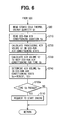
- Fig. 4 is a graph showing the transition of the evaporator blow temperature Te and the cold thermal energy storage unit blow temperature Tc in the normal air conditioning mode and in the eco-run air conditioning mode.
- a cold thermal energy quantity Q1 stored in the cold thermal energy storage material 44 is a heat quantity, after both the temperatures Tc and Te are equal to or lower than the solidifying point To of the cold thermal energy storage material 44.
- the quantity Q1 is also dependent upon a cold thermal energy storage time, stored by the temperature difference (Tc - Te) of the cold thermal energy storage unit 40.
- the stored cold thermal energy quantity is also affected by the volume of cold air passed through the cold thermal energy storage unit 40, that is the volume of air blown into the cabin.
- the cold thermal energy quantity Q1 stored in the cold thermal energy storage material 44 can be calculated based on the above cold thermal energy storage time, the temperature difference (Tc - Te) of the cold thermal energy storage unit 40 before and after cold thermal energy storage, and the volume of cold air.
- the cold thermal energy quantity Q1 stored in the cold thermal energy storage material 44 is calculated in the next step S50 by Equations 1 and 2.
- C1 is a correction coefficient in view of the heat transfer rate of the cold thermal energy storage unit 40, the solidifying latent heat of the cold thermal energy storage material 44 and the like.
- the stored cold thermal energy quantity Q1n calculated for the prescribed time intervals "to” are each integrated into the following Equation 2, and based on the result of integration, the total stored cold thermal energy quantity Q1, i.e., the "stored cold thermal energy quantity Q1 immediately before the transition to the eco-run air conditioning mode" is calculated.
- Equation 2 the numbers in the parentheses represent ordinal numbers in calculations like the first time, the second time, the third time.
- the stored cold thermal energy quantity Q ⁇ at the end of the cold thermal energy storage can previously be calculated based on the solidifying latent heat (heat quantity per unit weight) of the cold thermal energy storage material 44 and the weight of the cold thermal energy storage material 44. Therefore, the integration of Q1n in Equation 2 may end when the calculated value for the stored cold thermal energy quantity Q1 reaches the "stored cold thermal energy quantity Q ⁇ at the end of the cold thermal energy storage" calculated in advance.
- step S40 When the result of determination in step S40 is NO, latent heat cold thermal energy storage by solidification of the cold thermal energy storage material 44 cannot take place due to the conditions, and control returns to step S20.
- step S20 when an eco-run air conditioning mode is determined in step S20, the control proceeds to step S60 and control under the eco-run air conditioning mode begins.
- step S60 the stored cold thermal energy quantity Q1 calculated in step S50 is read.
- the eco-run state control is carried out to the air conditioner in step S70. More specifically, air volume control, air mix door control, indoor and outdoor air intake control, blow mode control and the like in the eco-run air conditioning mode are carried out by a method according to the normal air conditioning mode.
- step S80 radiated cold thermal energy quantity Q2 from the cold thermal energy storage material 44 in the eco-run air conditioning mode is calculated.
- step S90 the stored cold thermal energy remaining time "to" is calculated. The radiated cold thermal energy quantity Q2' per unit time is then calculated.
- the radiated cold thermal energy quantity Q2 calculated by Equation 3 is converted into a numerical value per second to obtain Q2'.
- a signal for the stored cold thermal energy remaining time "to” is output to the indicator 36a of the air conditioning control panel 36, and the number (in seconds) of the cold thermal energy storage time "to” is indicated by the indicator 36a. In this way, passengers can be notified of the remaining time for eco-run air conditioning allowed by the cold thermal energy stored in the cold thermal energy storage unit 40.
- step S100 It is determined in the next step S100 whether the stored cold thermal energy remaining time "to" is 0.
- the control proceeds to step S110, and an operation request to the vehicle engine 4 is output to the engine electronic control unit 38, so that the vehicle engine 4 is automatically started.
- the determination result in step S20 is NO and the normal air conditioning mode is resumed.
- Tco represents a cold thermal energy storage unit blow temperature when the vehicle engine 4 is started after the end of the eco-run air conditioning mode. Tco is preferably approximately not more than 14°C in order to secure the comfort of the passengers to make them feel cool enough and to prevent odors from being emitted from the evaporator 9.
- step S40 the point when the evaporator blow temperature Te and the cold thermal energy storage unit blow temperature Tc both reach the solidifying point To (8°C in this embodiment) of the cold thermal energy storage material 44, or lower, is determined as the starting point of latent heat cold thermal energy storage to the cold thermal energy storage material 44.
- the cold thermal energy storage unit blow temperature Tc is equal to or lower than the solidifying point To of the cold thermal energy storage material 44, as shown in Fig. 4, the evaporator blow temperature Te is also equal to or lower than the solidifying point To of the cold thermal energy storage material 44. Therefore, the determination in step S40 may be made based only on the cold thermal energy storage unit blow temperature Tc.
- step S40 may be made based only on the evaporator blow temperature Te.
- the cold thermal energy quantity Q1 stored in the cold thermal energy storage material 44 is calculated based on the cold thermal energy storage time after the cold thermal energy storage unit blow temperature Tc becomes at least equal to or lower than cold thermal energy storage material solidifying point To, the temperature difference (Tc-Te) of the cold thermal energy storage unit 40 before and after cold thermal energy storage, and the volume of cold air. Additionally, the calculation process for the stored cold thermal energy quantity Q1 may be simplified as follows.
- the discharge capability of the compressor 1 is controlled (the control of the operation ratio in continuation/interruption of the compressor 1, and the control of the discharge capacity of the compressor 1) so that the evaporator blow temperature Te upstream of the cold thermal energy storage unit 40 is normally fixed in the vicinity of 3°C to 4°C except for the transition period immediately after the start of cooling in order to prevent the evaporator 9 from frosting. Therefore, after Tc and Te are both equal to or lower than the solidifying point To of the cold thermal energy storage material, the ratio of the period, in which the evaporator blow temperature Te is kept substantially at a fixed level, is high. Stated differently, the ratio of the period, in which the temperature of air drawn through the cold thermal energy storage unit 40, kept substantially at a fixed level, is high.
- the cold thermal energy quantity Q1 stored in the cold thermal energy storage material 44 is calculated by the above Equations 1 and 2 in step S50.
- the cold thermal energy storage unit blow temperature Tc is equal to or lower than the solidifying point To of the cold thermal energy storage material, latent heat cold thermal energy storage to the cold thermal energy storage material 44 begins.
- the cold thermal energy storage unit blow temperature Tc is lowered to the evaporator blow temperature Te, it can be determined that the cold thermal energy storage to the cold thermal energy storage material 44 is complete.
- the time tx, passed after the cold thermal energy storage unit blow temperature Tc reaches the solidifying point To or lower of the cold thermal energy storage material, is measured and the stored cold thermal energy quantity Q1 is calculated based on that passed time tx.
- Fig. 5 is a graph showing the concept of how to calculate the stored cold thermal energy quantity Q1 according to the second embodiment.
- the ratio of the period in which the evaporator blow temperature Te is kept substantially fixed is high except for the transition period immediately after the start of cooling, as described above, in order to prevent the evaporator 9 from frosting. Therefore the ratio of the period, in which the temperature of air drawn through the cold thermal energy storage unit 40 is kept substantially fixed, is high.
- tf1 represents time until the end of cold thermal energy storage when the air volume is the minimum volume, Lo
- tf2 represents time until the end of cold thermal energy storage when the air volume is the maximum volume, Hi.
- the stored cold thermal energy quantity Q ⁇ at the end of the cold thermal energy storage can, in advance, be calculated based on the solidifying latent heat (heat quantity per unit weight) of the cold thermal energy storage material 44 and the weight of the cold thermal energy storage material 44. Therefore, time tf1, tf2 until the end of the cold thermal energy storage for each air volume obtained by experiments in advance and the stored cold thermal energy quantity Q ⁇ at the end of the cold thermal energy storage calculated in advance are stored in storage means in the control unit 5, and the passed time tx is measured. In this way, for the minimum air volume Lo, the stored cold thermal energy quantity Q1 at present, while the vehicle is moving, can be calculated as: Stored cold thermal energy quantity Q ⁇ at the end of the cold thermal energy storage ⁇ (tx/tf1).
- the stored cold thermal energy quantity Q1 at present while the vehicle is moving can be calculated as: Stored cold thermal energy quantity Q ⁇ at the end of the cold thermal energy storage ⁇ (tx/tf2).
- each of the air volumes for tf1 and tf2, of which times run until the end of cold thermal energy storage may be an air volume when Tc is not more than the solidifying point To of the cold thermal energy storage material.
- the average value of the air volumes within the passed time tx may be calculated and time tf1, tf2 until the end of cold thermal energy storage can be selected using the average air volume value.
- the stored cold thermal energy remaining time "to” can be calculated based on the stored cold thermal energy quantity Q1 calculated during the operation of the vehicle engine 4 (while the vehicle is moving), and the value of the stored cold thermal energy remaining time “to” (seconds) is indicated at the indicator 36a of the air conditioning control panel 36.
- the air volume control in the eco-run air conditioning control is carried out based on the stored cold thermal energy quantity Q1 calculated during the operation of the vehicle engine 4 (while the vehicle is moving).
- Fig. 6 is a flowchart for use in illustrating control in the eco-run air conditioning mode according to the third embodiment.
- steps S710 to S740 are for control of the air conditioner corresponding to step S70 in Fig. 3.
- the description of the third embodiment is specifically focused on the air volume control for the blower 11 among controls in the air conditioner.
- Other controls such as control of the opening of the air mix door 19 are the same as those of the conventional cases, and therefore will not be described.
- step S60 similar to the first embodiment, the stored cold thermal energy quantity Q1 calculated during the operation of the vehicle engine 4 (while the vehicle is moving) is read. Then in step S710, the duration tb of the eco-run air conditioning mode is read.
- the duration tb is a pre-set, prescribed time period stored in the storage means of the control unit 5. Since it is usually the case that the vehicle waits for a green light for one minute at most, the duration tb is set to one minute for example in view of the actual signal waiting time.
- a provisional air volume V1 in the eco-run air conditioning mode is calculated based on a well-known method. More specifically, when the air volume is determined by auto control, the target blow temperature TAO of air blown into the cabin is calculated based on the set temperature Tset, the indoor air temperature Tr, the outdoor air temperature Tam, the value of solar radiation Ts, etc. in the temperature setting switch 37a. The calculation is carried out so that the lower the target blow temperature TAO is, the larger the provisional air volume V1 becomes.
- the air volume switch 37b When the air volume switch 37b is manually operated by the passenger and the air volume is indicated by manual operation, the air volume by manual operation using the air volume switch 37b is set as the provisional air volume V1.
- step S730 with the stored cold thermal energy quantity Q1 stored during the operation of the vehicle engine 4 (while the vehicle is moving), the air volume V2 to maintain the eco-run air conditioning for the above duration tb is calculated. How to calculate the air volume V2 will now be described more specifically.
- Equation 5 Q1/ ⁇ (Te-Tc) ⁇ tb ⁇ C2 ⁇
- Te and Tc in Equation 5 represent temperatures of air drawn across the cold thermal energy storage unit during the beginning of the eco-run air conditioning mode.
- Tc can be regarded as a fixed temperature determined by the solidifying point To of the cold thermal energy storage material, and therefore only Te representing the temperature of air drawn across the cold thermal energy storage unit is input in Equation 5 to calculate the air volume V2 without inputting Tc.
- step S740 the smaller value of the provisional air volume V1 and the air volume V2 determined by the stored cold thermal energy quantity Q1 and the radiated cold thermal energy quantity Q2, is finally determined as the air volume Vo during eco-run air conditioning. More specifically, when the temperature Te of air drawn across the cold thermal energy storage unit during eco-run air conditioning is low and the cooling load is small, the air volume V1 can be smaller than the air volume V2. In the case, the air volume V1 is selected to carry out the eco-run air conditioning mode, so that the air conditioning can be carried out in the cabin with the air volume appropriately corresponding to the air conditioning environmental conditions.
- the air volume V2 is smaller than the air volume V1. In that case, the air volume V2 is selected to carry out the eco-run air conditioning mode, so that eco-run air conditioning can be continued during the predetermined duration tb (one minute for example).
- step S100a corresponds to step S100 according to the first embodiment, and it is determined in the step whether the time duration tb is passed. When the duration tb passes, the control proceeds to step S110.
- step S110 a request to start the vehicle engine 4 is output to the engine electronic control unit 38, and the vehicle engine 4 is automatically started. In this way, the eco-run air conditioning mode ends, the result of the determination in step S20 is NO, and the control proceeds to the normal air conditioning mode control.
- the duration tb of the eco-run air conditioning mode is fixed to a prescribed value.
- road information such as how many seconds longer it will take before a traffic signal turns to green from red
- the duration tb may be varied based on the actual remaining time until the signal is switched from red to green.
- Equations 1 and 3 in calculating the cold thermal energy quantity Q1 stored in the cold thermal energy storage material 44 and the radiated cold thermal energy quantity Q2n to the cold thermal energy storage material 44, the temperature difference (Tc-Te) of the cold thermal energy storage unit 40 before and after cold thermal energy storage is used. Meanwhile, Tc can be regarded as a fixed temperature determined by the solidifying temperature To of the cold thermal energy storage material as described in connection with Equation 5 according to the third embodiment. Therefore, also in Equations 1 and 3, Te alone may be input to calculate the stored cold thermal energy quantity Q1 and the radiated cold thermal energy quantity Q2n without inputting Tc.
- temperature sensors 32 and 33 for detecting the blow air temperature of the evaporator 9 and the cold thermal energy storage unit 40 are provided. Meanwhile, temperature sensors for detecting surface temperatures or the like of the evaporator 9 and the cold thermal energy storage unit 40 may be used as the temperature detecting means for the evaporator 9 and the cold thermal energy storage unit 40.
Landscapes
- Physics & Mathematics (AREA)
- Thermal Sciences (AREA)
- Engineering & Computer Science (AREA)
- Mechanical Engineering (AREA)
- Air-Conditioning For Vehicles (AREA)
Abstract
Description
Claims (7)
- A vehicle air conditioner operating according to a refrigeration cycle (R) when a vehicle engine (4) is not operating, the air conditioner comprising:a compressor (1) driven by the vehicle engine (4);an evaporator (9) provided as part of the refrigeration cycle (R), wherein said compressor (1) and said evaporator (9) are for cooling air blown into a vehicle interior; anda cold thermal energy storage unit (40) provided downstream side of said evaporator (9) in an air path and cooled by cold air passed through said evaporator (9), whereinair blown into the cabin is cooled by a stored cold thermal energy quantity from said cold thermal energy storage unit (40) when the vehicle engine (4) is stopped,the cold thermal energy storage unit (40) has a cold thermal energy storage material (44) cooled and solidified by the cold air passed through said evaporator (9),during the operation of said vehicle engine (4), a cold thermal energy storage time after a temperature of said cold thermal energy storage unit (40) reaches a solidifying point of said cold thermal energy storage material (44) or lower until cold thermal energy storage to said cold thermal energy storage material (44) is carried out is measured,the stored cold thermal energy quantity of said cold thermal energy storage material (44) during the operation of said vehicle engine (4) is calculated based on at least said cold thermal energy storage time and a volume of said cold air.
- The vehicle air conditioner according to claim 1, further comprising:a temperature detecting means (32) for detecting a temperature of said evaporator (9); anda temperature detecting means (33) for detecting the temperature of said cold thermal energy storage unit (40), whereinsaid stored cold thermal energy quantity is calculated based on said cold thermal energy storage time, said volume of said cold air, said temperature of said evaporator (9), and said temperature of said cold thermal energy storage unit (40).
- A vehicle air conditioner that is mounted on a vehicle, which carries out control to stop a vehicle engine (4) when power of the vehicle engine (4) is not necessary, the air conditioner comprising:a compressor (1) driven by the vehicle engine (4);an evaporator (9) provided in a refrigeration cycle (R) having said compressor (1) for cooling air blown into a vehicle cabin; anda cold thermal energy storage unit (40) provided on a downstream side of said evaporator (9) and cooled by cold air passed through said evaporator (9), whereinair blown into the cabin being cooled by a stored cold thermal energy quantity of said cold thermal energy storage unit (40) when said vehicle engine (4) is stopped,said cold thermal energy storage unit (40) having a cold thermal energy storage material (44) cooled and solidified by the cold air passed through said evaporator (9),during the operation of said vehicle engine (4), a cold thermal energy storage completion time after a temperature of said cold thermal energy storage unit (40) reaches a solidifying point of said cold thermal energy storage material (44), or lower, until cold thermal energy storage to said cold thermal energy storage material (44) is completed is pre-set for each air volume of said cold air,during the operation of the vehicle engine (4), the time passed after the temperature of said cold thermal energy storage unit (40) reaches a solidifying point of said cold thermal energy storage material (44) or lower is measured,said pre-set cold thermal energy storage completion time is selected based on an actual cold air volume after said temperature of said cold thermal energy storage unit (40) reaches a solidifying point of said cold thermal energy storage material (44), or lower, and said stored cold thermal energy quantity of said cold thermal energy storage material (44) during the operation of said vehicle engine (4) is calculated based on a ratio of said passed time relative to said selected cold thermal energy storage completion time.
- A vehicle air conditioner to be mounted on a vehicle that carries out control to stop a vehicle engine (4) when power of said vehicle engine (4) is not necessary, comprising:a compressor (1) driven by said vehicle engine (4);an evaporator (9) provided in a refrigeration cycle (R) having said compressor (1) for cooling air blown into a vehicle cabin; anda cold thermal energy storage unit (40) provided at a downstream air location of said evaporator (9) and cooled by cold air passed through said evaporator (9), whereinair blown into said vehicle cabin is cooled by a stored cold thermal energy quantity of said cold thermal energy storage unit (40) when said vehicle engine (4) is stopped,said cold thermal energy storage unit (40) has a cold thermal energy storage material (44) cooled and solidified by said cold air passed through said evaporator (9),a stored cold thermal energy quantity calculating means (S50) calculates the stored cold thermal energy quantity of said cold thermal energy storage material (44) during the operation of said vehicle engine (4),when said vehicle engine (4) is stopped, a volume of air blown into the cabin that can be cooled by cold thermal energy radiation of said cold thermal energy storage material (44) for a prescribed duration is calculated based on information including at least said stored cold thermal energy quantity and said duration,the volume of air blown into said vehicle cabin when said vehicle engine (4) is stopped is controlled to be said calculated air volume.
- The vehicle air conditioner according to claim 4, wherein said calculated air volume is based on at least said stored cold thermal energy quantity, said duration, and a temperature of air drawn through said cold thermal energy storage unit (40).
- The vehicle air conditioner according to claim 4, wherein
when said vehicle engine (4) is stopped, an air volume manually set using an air conditioning control panel (36), or an air volume automatically set by automatic control, is calculated as a first volume of air blown into the cabin,
said calculated air volume is a second air volume, and
the smaller air volume of said first and second air volumes is selected as said volume of air blown into the cabin when the vehicle engine (4) is stopped. - The vehicle air conditioner according to claim 5, wherein
when said vehicle engine (4) is stopped, an air volume manually set using an air conditioning control panel (36), or an air volume automatically set by automatic control, is calculated as a first volume of air blown into the cabin,
said calculated air volume is a second air volume, and
the smaller air volume of said first and second air volumes is selected as said volume of air blown into the cabin when the vehicle engine (4) is stopped.
Applications Claiming Priority (2)
| Application Number | Priority Date | Filing Date | Title |
|---|---|---|---|
| JP2001359586 | 2001-11-26 | ||
| JP2001359586A JP3801027B2 (en) | 2001-11-26 | 2001-11-26 | Air conditioner for vehicles |
Publications (3)
| Publication Number | Publication Date |
|---|---|
| EP1314590A2 true EP1314590A2 (en) | 2003-05-28 |
| EP1314590A3 EP1314590A3 (en) | 2005-05-18 |
| EP1314590B1 EP1314590B1 (en) | 2006-09-06 |
Family
ID=19170562
Family Applications (1)
| Application Number | Title | Priority Date | Filing Date |
|---|---|---|---|
| EP02026346A Expired - Lifetime EP1314590B1 (en) | 2001-11-26 | 2002-11-22 | Vehicle air conditioner that operates during engine stops |
Country Status (4)
| Country | Link |
|---|---|
| US (1) | US6606877B2 (en) |
| EP (1) | EP1314590B1 (en) |
| JP (1) | JP3801027B2 (en) |
| DE (1) | DE60214498T2 (en) |
Cited By (5)
| Publication number | Priority date | Publication date | Assignee | Title |
|---|---|---|---|---|
| EP1609638A3 (en) * | 2004-06-23 | 2006-11-08 | Behr GmbH & Co. KG | Method for the operation of an air conditioning for vehicles |
| WO2007128455A1 (en) * | 2006-05-05 | 2007-11-15 | Behr Gmbh & Co. Kg | Method for operating a motor vehicle air conditioning system |
| FR2909040A1 (en) * | 2006-11-23 | 2008-05-30 | Valeo Systemes Thermiques | Temperature controlling system for cab interior of e.g. hybrid vehicle, has CPU emitting engine restarting control and engine stopping inhibiting signals towards control unit, when evaporating temperature signal exceeds threshold values |
| CN104254745A (en) * | 2012-03-21 | 2014-12-31 | 德尔福技术有限公司 | Phase change material evaporator charging control |
| CN105082940A (en) * | 2014-05-09 | 2015-11-25 | 苏峻苇 | Automobile cabin rapid cooling system and control method thereof and energy accumulator therein |
Families Citing this family (41)
| Publication number | Priority date | Publication date | Assignee | Title |
|---|---|---|---|---|
| WO2003014634A1 (en) | 2001-08-07 | 2003-02-20 | Bsst Llc | Thermoelectric personal environment appliance |
| JP3979051B2 (en) * | 2001-09-18 | 2007-09-19 | 株式会社デンソー | Air conditioner for vehicles |
| US20030116368A1 (en) * | 2001-12-20 | 2003-06-26 | Winkelman James R. | Accessory drive for vehicle with hybrid drive system |
| JP2004224133A (en) * | 2003-01-21 | 2004-08-12 | Kobelco Contstruction Machinery Ltd | Power controller for construction machine |
| US7032393B2 (en) * | 2003-08-28 | 2006-04-25 | General Motors Corporation | Climate cooling control systems and methods for hybrid vehicles |
| WO2005021300A1 (en) * | 2003-09-03 | 2005-03-10 | Halla Climate Control Corp. | Controlling method of air conditioning system for vehicles |
| US7134483B2 (en) * | 2003-09-26 | 2006-11-14 | Flair Corporation | Refrigeration-type dryer apparatus and method |
| US7380586B2 (en) | 2004-05-10 | 2008-06-03 | Bsst Llc | Climate control system for hybrid vehicles using thermoelectric devices |
| US6988371B2 (en) * | 2004-05-25 | 2006-01-24 | General Motors Corporation | Automotive HVAC system and method of operating same utilizing evaporator freezing |
| US7063138B2 (en) * | 2004-05-25 | 2006-06-20 | General Motors Corporation | Automotive HVAC system and method of operating same utilizing trapped coolant |
| US7743614B2 (en) | 2005-04-08 | 2010-06-29 | Bsst Llc | Thermoelectric-based heating and cooling system |
| US8783397B2 (en) * | 2005-07-19 | 2014-07-22 | Bsst Llc | Energy management system for a hybrid-electric vehicle |
| US7870745B2 (en) | 2006-03-16 | 2011-01-18 | Bsst Llc | Thermoelectric device efficiency enhancement using dynamic feedback |
| US7779639B2 (en) | 2006-08-02 | 2010-08-24 | Bsst Llc | HVAC system for hybrid vehicles using thermoelectric devices |
| US20100155018A1 (en) | 2008-12-19 | 2010-06-24 | Lakhi Nandlal Goenka | Hvac system for a hybrid vehicle |
| WO2008148042A2 (en) | 2007-05-25 | 2008-12-04 | Bsst Llc | System and method for distributed thermoelectric heating and colling |
| US20090191804A1 (en) * | 2008-01-29 | 2009-07-30 | Lakhi Nandlal Goenka | Heating, ventilating, and air conditioning system having a thermal energy exchanger |
| US20090188266A1 (en) * | 2008-01-29 | 2009-07-30 | Stephen Think Hung | Heating, ventilating, and air conditioning system having a thermal energy exchanger |
| US8302417B2 (en) * | 2008-04-23 | 2012-11-06 | GM Global Technology Operations LLC | Air conditioning system with cold thermal storage and evaporator temperature control |
| US8701422B2 (en) | 2008-06-03 | 2014-04-22 | Bsst Llc | Thermoelectric heat pump |
| US9447994B2 (en) | 2008-10-23 | 2016-09-20 | Gentherm Incorporated | Temperature control systems with thermoelectric devices |
| US9555686B2 (en) | 2008-10-23 | 2017-01-31 | Gentherm Incorporated | Temperature control systems with thermoelectric devices |
| EP2946953A1 (en) | 2008-10-23 | 2015-11-25 | Bsst Llc | Multi-mode hvac system with thermoelectric device |
| KR102112970B1 (en) | 2009-05-18 | 2020-05-19 | 젠썸 인코포레이티드 | Battery thermal management system |
| CN104914896B (en) | 2009-05-18 | 2017-06-13 | 詹思姆公司 | temperature control system with thermoelectric device |
| JP5316321B2 (en) | 2009-09-02 | 2013-10-16 | 株式会社デンソー | Air conditioner for vehicles |
| JP2011068190A (en) * | 2009-09-24 | 2011-04-07 | Denso Corp | Air-conditioning control device for vehicle |
| DE102010037446B4 (en) * | 2010-09-10 | 2026-01-15 | Ford Global Technologies, Llc. | Methods for controlling an air conditioning system and air conditioning |
| DE112012002935T5 (en) | 2011-07-11 | 2014-05-15 | Gentherm Inc. | Thermoelectric based thermal management of electrical devices |
| US9389007B1 (en) * | 2013-01-09 | 2016-07-12 | New West Technologies, LLC | Transportation refrigeration system with integrated power generation and energy storage |
| US20140196489A1 (en) * | 2013-01-11 | 2014-07-17 | University Of Dayton | Energy-optimized cycle control of time-variant loads for thermal management of vapor compression systems |
| JP6156776B2 (en) * | 2013-02-19 | 2017-07-05 | スズキ株式会社 | Air conditioning control device for vehicles |
| US9333832B2 (en) * | 2014-04-08 | 2016-05-10 | Honda Motor Co., Ltd. | System and method for providing an air conditioner efficiency control for a vehicle |
| CN107249910B (en) | 2014-12-19 | 2021-01-15 | 詹思姆公司 | Thermal conditioning system and method for a vehicle area |
| WO2017065847A1 (en) | 2015-10-14 | 2017-04-20 | Gentherm Incorporated | Systems and methods for controlling thermal conditioning of vehicle regions |
| JP6671018B2 (en) * | 2016-03-09 | 2020-03-25 | パナソニックIpマネジメント株式会社 | Cool storage device, method of displaying information indicating state of cold storage body, and method of obtaining information indicating state of cold storage body |
| US11148503B2 (en) * | 2016-12-14 | 2021-10-19 | Mahle Behr Thermal Systems (Japan) Company Limited | Evaporator with cool storage function |
| CN106642386A (en) * | 2016-12-16 | 2017-05-10 | 宁波保税区瑞丰模具科技有限公司 | Dehumidifier |
| JP2018167704A (en) * | 2017-03-30 | 2018-11-01 | 株式会社デンソー | Air conditioner |
| CN121230238A (en) | 2018-11-30 | 2025-12-30 | 金瑟姆股份公司 | Thermoelectric control systems and methods |
| US11970044B2 (en) * | 2020-10-30 | 2024-04-30 | Ford Global Technologies, Llc | Heating and cooling system for a vehicle |
Family Cites Families (14)
| Publication number | Priority date | Publication date | Assignee | Title |
|---|---|---|---|---|
| DE2416807A1 (en) * | 1974-04-06 | 1975-10-23 | Daimler Benz Ag | THERMAL PROTECTION FOR A VEHICLE ACCUMULATOR |
| US4761967A (en) * | 1984-10-11 | 1988-08-09 | Diesel Kiki Kabushiki Kaisha | Car air conditioner with heat storage tank for cooling energy |
| JPH01153321A (en) | 1987-12-10 | 1989-06-15 | Suzuki Motor Co Ltd | Regenerative type air-conditioning device for vehicle |
| EP0554482A1 (en) * | 1992-02-05 | 1993-08-11 | C B F INTERNATIONAL Srl | Cold accumulator |
| JPH06211029A (en) * | 1993-01-18 | 1994-08-02 | Nissan Motor Co Ltd | Cooling device for automobile |
| JPH08192619A (en) * | 1995-01-19 | 1996-07-30 | Nippondenso Co Ltd | Cold and heat storage type air conditioner |
| JPH0999731A (en) * | 1995-10-05 | 1997-04-15 | Denso Corp | Adsorption type air conditioner |
| WO1998015420A1 (en) * | 1996-10-01 | 1998-04-16 | Toyota Jidosha Kabushiki Kaisha | Air conditioning apparatus for vehicle |
| JPH10157449A (en) * | 1996-11-28 | 1998-06-16 | Denso Corp | Refrigeration cycle device |
| JP3494021B2 (en) | 1998-07-21 | 2004-02-03 | トヨタ自動車株式会社 | Vehicle air conditioner |
| DE19838880C5 (en) * | 1998-08-27 | 2005-05-04 | Behr Gmbh & Co. Kg | Device for cooling an interior of a motor vehicle |
| JP4174929B2 (en) * | 1998-10-23 | 2008-11-05 | 株式会社デンソー | Air conditioner for vehicles |
| JP3094104B1 (en) * | 1999-08-31 | 2000-10-03 | 工業技術院長 | Superconducting magnetic levitation transport system |
| DE10124757A1 (en) | 2000-05-26 | 2001-11-29 | Denso Corp | Vehicle air conditioning system has cold storage device between cold heat exchanger downstream side, flap upstream aide cooled by cold air after passing through cold heat exchanger |
-
2001
- 2001-11-26 JP JP2001359586A patent/JP3801027B2/en not_active Expired - Fee Related
-
2002
- 2002-11-20 US US10/300,181 patent/US6606877B2/en not_active Expired - Lifetime
- 2002-11-22 EP EP02026346A patent/EP1314590B1/en not_active Expired - Lifetime
- 2002-11-22 DE DE60214498T patent/DE60214498T2/en not_active Expired - Lifetime
Cited By (7)
| Publication number | Priority date | Publication date | Assignee | Title |
|---|---|---|---|---|
| EP1609638A3 (en) * | 2004-06-23 | 2006-11-08 | Behr GmbH & Co. KG | Method for the operation of an air conditioning for vehicles |
| WO2007128455A1 (en) * | 2006-05-05 | 2007-11-15 | Behr Gmbh & Co. Kg | Method for operating a motor vehicle air conditioning system |
| FR2909040A1 (en) * | 2006-11-23 | 2008-05-30 | Valeo Systemes Thermiques | Temperature controlling system for cab interior of e.g. hybrid vehicle, has CPU emitting engine restarting control and engine stopping inhibiting signals towards control unit, when evaporating temperature signal exceeds threshold values |
| CN104254745A (en) * | 2012-03-21 | 2014-12-31 | 德尔福技术有限公司 | Phase change material evaporator charging control |
| US9400510B2 (en) | 2012-03-21 | 2016-07-26 | Mahle International Gmbh | Phase change material evaporator charging control |
| CN104254745B (en) * | 2012-03-21 | 2016-10-05 | 马勒国际有限公司 | Phase-change material vaporizer fills can control |
| CN105082940A (en) * | 2014-05-09 | 2015-11-25 | 苏峻苇 | Automobile cabin rapid cooling system and control method thereof and energy accumulator therein |
Also Published As
| Publication number | Publication date |
|---|---|
| EP1314590B1 (en) | 2006-09-06 |
| JP2003159936A (en) | 2003-06-03 |
| US6606877B2 (en) | 2003-08-19 |
| DE60214498T2 (en) | 2007-05-31 |
| US20030097852A1 (en) | 2003-05-29 |
| DE60214498D1 (en) | 2006-10-19 |
| JP3801027B2 (en) | 2006-07-26 |
| EP1314590A3 (en) | 2005-05-18 |
Similar Documents
| Publication | Publication Date | Title |
|---|---|---|
| EP1314590B1 (en) | Vehicle air conditioner that operates during engine stops | |
| US6820436B2 (en) | Vehicle air-conditioning system with cold storage unit | |
| US6688120B2 (en) | Vehicle air conditioner with cold storage and cold release | |
| US6314750B1 (en) | Heat pump air conditioner | |
| US10293661B2 (en) | Vehicle air conditioning apparatus | |
| JP3480410B2 (en) | Vehicle air conditioner | |
| EP0751356B1 (en) | Air conditioning apparatus | |
| US6708512B2 (en) | Vehicle air conditioner with cold accumulator | |
| US6073456A (en) | Air-conditioning device for hybrid vehicle | |
| JP3972501B2 (en) | Heat exchange device for heat storage and air conditioner for vehicle | |
| US6854513B2 (en) | Vehicle air conditioning system with cold accumulator | |
| US20010049943A1 (en) | Air-conditioning system for vehicles | |
| JP2000094942A (en) | Electric vehicle air conditioner | |
| US20170368940A9 (en) | Vehcile air conditioning apparatus | |
| JP2002337537A (en) | Vehicle air conditioner | |
| JPH08197937A (en) | Air conditioner for vehicle | |
| JP3876762B2 (en) | Air conditioner for vehicles | |
| WO2023276626A1 (en) | Heat pump cycle apparatus | |
| JP4443812B2 (en) | Air conditioner for vehicles | |
| JP2004182165A (en) | Vehicle air conditioner | |
| JP2000219028A (en) | Vehicle air conditioner | |
| JP2001213151A (en) | Vehicle air conditioner | |
| JP2004291759A (en) | Vehicle air conditioner | |
| JP3456021B2 (en) | Vehicle air conditioner | |
| JP2002154319A (en) | Vehicle air conditioner |
Legal Events
| Date | Code | Title | Description |
|---|---|---|---|
| PUAI | Public reference made under article 153(3) epc to a published international application that has entered the european phase |
Free format text: ORIGINAL CODE: 0009012 |
|
| AK | Designated contracting states |
Designated state(s): AT BE BG CH CY CZ DE DK EE ES FI FR GB GR IE IT LI LU MC NL PT SE SK TR |
|
| AX | Request for extension of the european patent |
Extension state: AL LT LV MK RO SI |
|
| PUAL | Search report despatched |
Free format text: ORIGINAL CODE: 0009013 |
|
| AK | Designated contracting states |
Kind code of ref document: A3 Designated state(s): AT BE BG CH CY CZ DE DK EE ES FI FR GB GR IE IT LI LU MC NL PT SE SK TR |
|
| AX | Request for extension of the european patent |
Extension state: AL LT LV MK RO SI |
|
| 17P | Request for examination filed |
Effective date: 20050603 |
|
| AKX | Designation fees paid |
Designated state(s): DE FR IT |
|
| GRAP | Despatch of communication of intention to grant a patent |
Free format text: ORIGINAL CODE: EPIDOSNIGR1 |
|
| GRAS | Grant fee paid |
Free format text: ORIGINAL CODE: EPIDOSNIGR3 |
|
| GRAA | (expected) grant |
Free format text: ORIGINAL CODE: 0009210 |
|
| AK | Designated contracting states |
Kind code of ref document: B1 Designated state(s): DE FR IT |
|
| PG25 | Lapsed in a contracting state [announced via postgrant information from national office to epo] |
Ref country code: IT Free format text: LAPSE BECAUSE OF FAILURE TO SUBMIT A TRANSLATION OF THE DESCRIPTION OR TO PAY THE FEE WITHIN THE PRESCRIBED TIME-LIMIT;WARNING: LAPSES OF ITALIAN PATENTS WITH EFFECTIVE DATE BEFORE 2007 MAY HAVE OCCURRED AT ANY TIME BEFORE 2007. THE CORRECT EFFECTIVE DATE MAY BE DIFFERENT FROM THE ONE RECORDED. Effective date: 20060906 |
|
| REF | Corresponds to: |
Ref document number: 60214498 Country of ref document: DE Date of ref document: 20061019 Kind code of ref document: P |
|
| ET | Fr: translation filed | ||
| PLBE | No opposition filed within time limit |
Free format text: ORIGINAL CODE: 0009261 |
|
| STAA | Information on the status of an ep patent application or granted ep patent |
Free format text: STATUS: NO OPPOSITION FILED WITHIN TIME LIMIT |
|
| 26N | No opposition filed |
Effective date: 20070607 |
|
| REG | Reference to a national code |
Ref country code: FR Ref legal event code: PLFP Year of fee payment: 14 |
|
| REG | Reference to a national code |
Ref country code: FR Ref legal event code: PLFP Year of fee payment: 15 |
|
| PGFP | Annual fee paid to national office [announced via postgrant information from national office to epo] |
Ref country code: DE Payment date: 20161121 Year of fee payment: 15 Ref country code: FR Payment date: 20161118 Year of fee payment: 15 |
|
| PGFP | Annual fee paid to national office [announced via postgrant information from national office to epo] |
Ref country code: IT Payment date: 20161123 Year of fee payment: 15 |
|
| REG | Reference to a national code |
Ref country code: DE Ref legal event code: R119 Ref document number: 60214498 Country of ref document: DE |
|
| REG | Reference to a national code |
Ref country code: FR Ref legal event code: ST Effective date: 20180731 |
|
| PG25 | Lapsed in a contracting state [announced via postgrant information from national office to epo] |
Ref country code: FR Free format text: LAPSE BECAUSE OF NON-PAYMENT OF DUE FEES Effective date: 20171130 Ref country code: IT Free format text: LAPSE BECAUSE OF NON-PAYMENT OF DUE FEES Effective date: 20171122 Ref country code: DE Free format text: LAPSE BECAUSE OF NON-PAYMENT OF DUE FEES Effective date: 20180602 |