EP1314506A2 - Gewindeschneidwerkzeug - Google Patents
Gewindeschneidwerkzeug Download PDFInfo
- Publication number
- EP1314506A2 EP1314506A2 EP02023852A EP02023852A EP1314506A2 EP 1314506 A2 EP1314506 A2 EP 1314506A2 EP 02023852 A EP02023852 A EP 02023852A EP 02023852 A EP02023852 A EP 02023852A EP 1314506 A2 EP1314506 A2 EP 1314506A2
- Authority
- EP
- European Patent Office
- Prior art keywords
- cutting
- undercut
- thread
- tool according
- cutting tool
- Prior art date
- Legal status (The legal status is an assumption and is not a legal conclusion. Google has not performed a legal analysis and makes no representation as to the accuracy of the status listed.)
- Granted
Links
Images

Classifications
-
- B—PERFORMING OPERATIONS; TRANSPORTING
- B23—MACHINE TOOLS; METAL-WORKING NOT OTHERWISE PROVIDED FOR
- B23G—THREAD CUTTING; WORKING OF SCREWS, BOLT HEADS, OR NUTS, IN CONJUNCTION THEREWITH
- B23G5/00—Thread-cutting tools; Die-heads
- B23G5/02—Thread-cutting tools; Die-heads without means for adjustment
- B23G5/06—Taps
-
- Y—GENERAL TAGGING OF NEW TECHNOLOGICAL DEVELOPMENTS; GENERAL TAGGING OF CROSS-SECTIONAL TECHNOLOGIES SPANNING OVER SEVERAL SECTIONS OF THE IPC; TECHNICAL SUBJECTS COVERED BY FORMER USPC CROSS-REFERENCE ART COLLECTIONS [XRACs] AND DIGESTS
- Y10—TECHNICAL SUBJECTS COVERED BY FORMER USPC
- Y10T—TECHNICAL SUBJECTS COVERED BY FORMER US CLASSIFICATION
- Y10T408/00—Cutting by use of rotating axially moving tool
- Y10T408/89—Tool or Tool with support
- Y10T408/904—Tool or Tool with support with pitch-stabilizing ridge
- Y10T408/9046—Tool or Tool with support with pitch-stabilizing ridge including tapered section
- Y10T408/90467—Tool or Tool with support with pitch-stabilizing ridge including tapered section and relieved cutting edge
-
- Y—GENERAL TAGGING OF NEW TECHNOLOGICAL DEVELOPMENTS; GENERAL TAGGING OF CROSS-SECTIONAL TECHNOLOGIES SPANNING OVER SEVERAL SECTIONS OF THE IPC; TECHNICAL SUBJECTS COVERED BY FORMER USPC CROSS-REFERENCE ART COLLECTIONS [XRACs] AND DIGESTS
- Y10—TECHNICAL SUBJECTS COVERED BY FORMER USPC
- Y10T—TECHNICAL SUBJECTS COVERED BY FORMER US CLASSIFICATION
- Y10T408/00—Cutting by use of rotating axially moving tool
- Y10T408/89—Tool or Tool with support
- Y10T408/904—Tool or Tool with support with pitch-stabilizing ridge
- Y10T408/9048—Extending outwardly from tool-axis
Definitions
- the present invention relates to a threading tool for cutting Internal threads with a shank and a cutting section made up of several each Group of cutting teeth with axially parallel or spirally arranged cutting studs and there are flutes running between them.
- thread cutting tool is intended to mean so-called taps, however also include certain types of thread milling cutters, insofar as they are used for the production of Internal threads are provided.
- Such a tapping tool either provides itself the threaded hole, specifically the core hole of a thread, or it is in an already prepared hole is screwed in, the diameter of which in one, generally of the material of the workpiece depending on the ratio to the final thread diameter stands.
- the thread cutting tool is precisely matched to its speed Feed screwed into the hole, the cutting teeth, which are in several in essentially parallel groups (called cutting tunnels) are arranged, the Cut threads. With a single-start thread, the distance corresponds to the in axially in each case one behind the other arranged cutting teeth of a group Thread pitch or the height of a thread.
- the so-called First cut the outside diameter of the cutting tool, starting from the Tip towards the back in the axial direction, the axially front cutting teeth being made wider and cut the wider, radially inner section of the thread grooves, while the subsequent cutting teeth are arranged on an increasingly larger radius are and in this way the thread grooves lying between the thread flanks Cut out to the desired depth, the thread grooves increasing Diameter, i.e. towards the bottom of the groove, are becoming narrower and the cutting teeth are accordingly designed with a narrower cutting back.
- the cross section the cutting teeth correspond to the cross section of the thread grooves to be produced, so that the Secondary cutting edges of the cutting teeth at the flank angle of the thread to each other run while the main cutting edge cuts the bottom of the thread groove.
- the front cutting teeth i.e. the cutting teeth in the gate area, which the Do not cut the thread groove to full depth yet, they are designed to be wide enough, because they create the further part of the thread profile.
- the one on the main cutting edge of a threaded stud subsequent open space generally has a clearance angle to that of the respective Main cutting edge generated peripheral surface in the order of 0.5 ° to 10 °, typically from 1 ° - 2 °.
- the object of the present invention is a thread cutting tool to create with the features mentioned, in which the wear is significantly reduced and which have significantly longer service lives than conventional ones Threading tools.
- These advantages are intended primarily for thread cutting in relatively hard and / or tough metallic materials, such as. B. stainless steel.
- the present invention is intended to achieve that the cutting edges of the Cutting teeth are less damaged even after long use of the thread cutting tool and in particular have fewer outbreaks.
- any chips can then be in this Accumulate free space, however, at least at the beginning of the reverse rotation will be no problem taken along, while the very narrow, wedge-shaped free space between open space and Circumferential surface limited to a very short section immediately behind the cutting edge remains, so that practically no chips can jam there, in particular there is The gap between the open area and the peripheral area is so narrow that there are practically no chips can penetrate.
- the undercut preferably begins at a distance behind the cutting edge, which is approximately 10 to 30% of the cutting tooth length measured in the circumferential direction. Preferably lies this distance between 15 and 25% of the cutting tooth length (measured in the circumferential direction).
- the undercut, starting from the open area, is relative begins abruptly with a return that has a predominantly radial component.
- a relatively steep, essentially radial transition surface is formed from the bottom of the undercut to that not covered by the undercut Part of the open space, and on this steep flank you may see the undercut accumulated chips very well transported in the reverse direction without the There is a risk that these shavings in the remaining narrow gap between the still penetrate the remaining open space section and the peripheral surface.
- the base of the undercut expediently runs, seen in an axial one Cut, essentially starting from the section of the open area near the cutting edge radially and then curved to the circumferential direction or simply angled. On this creates a relatively uniformly wide space between the bottom of the Undercut and the circumferential surface, which is enough space to accommodate any chips offers.
- the base of the undercut runs up to the rear end of the cutting tooth at least over half the cutting tooth length approximately parallel to the circumferential direction out.
- the base of the undercut from the radially starting from the innermost point, essentially parallel to the circumferential direction, i.e. the reason for the undercut is that of the cutting tooth Wall of the thread a largely constant distance.
- the reason for the undercut again runs slightly radially outwards, so that the rear end of the Cutting tooth towards the distance between the wall of the thread and the base of the undercut again somewhat decreased.
- the "wall" of the thread is in each case of the base of the groove in question.
- the maximum depth of the Undercut (measured in the radial direction) maintains a value that is between 2 and 10% the radius of the threading tool.
- this percentage value depends also from the absolute diameter of the respective thread or thread cutting tool from, since the depth of the undercut is relatively larger with small thread diameters must be than with large thread diameters.
- depths of the Undercut proven, which are in the range of 0.5 to 3 mm, the depth of the undercut here is also related to the cutting edge of the respective cutting tooth, i.e. the Depth is the difference between the radii of the cutting edge and the base of the undercut.
- a threading tool which is made of solid carbide
- solid carbide tools can be used with correspondingly difficult materials where there is a risk the damage or breaking out of cutting edges is particularly large, especially solid carbide tends to break out more easily than conventional tool steel.
- the present invention is particularly expedient to implement on cutting tools, where the groups of cutting teeth and the flutes essentially run parallel to the axis or with a very large spiral pitch, since these types of tools chip transport through the flutes is often particularly weak and therefore the invention takes advantage of the negative influences of the often still numerous chips avoids.
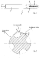
- FIG. 1 the thread cutting tool, designated overall by 1, in the form a tap, which has a shaft 2 and a cutting part 3.
- the shaft 2 is shown here as a simple cylindrical shaft, but it can also be any other Shape depending on how the corresponding chuck or chuck of a machine tool is designed.
- the cutting part 3 has several cutting studs 4, each consist of a group of cutting teeth 5, and has flutes running between them 6. In the present case, the flutes 6 and the cutting studs 4 or groups of run Cutting teeth on a relatively steep, spiral curve.
- FIG. 3 shows an enlargement of the cutting part 3.
- the cutting part 3 is in the axial direction divided into a so-called gate 14 and a guide portion 15 the main volume of the chips produced when cutting threads is almost exclusively generated in the gate area 14, while the guide part 15, as the name suggests, essentially the guide in the one already cut by the teeth of the gate area Threads.
- the cutting part is divided into cutting studs 4 and flutes 6.
- the cutting studs 4 each consist of an axially extending one Group of teeth 5, of which the front teeth, as already mentioned, form the gate and do not or only slightly cut the back teeth and, as well already mentioned, essentially only serve the guide in the thread, which also the teeth of the gate area exactly on the spiral path in the imaginary extension of the Threads are forced.
- the modification according to the invention in the illustrated embodiment is in have been essentially limited to the gate area 14, even if it is basically it would be possible to have all the free surfaces of the remaining teeth 5 of the cutting studs 4 in the illustrated Way to provide an undercut 7.
- the thread cutting tool shown here four groups 4 each of tapping teeth 5 and four in between arranged chip grooves 6.
- one of the cutting teeth shows the undercut provided according to the invention, which is shown enlarged again in FIG.
- FIG. 4 corresponds to a detail from FIG. 2 with an enlarged representation Cutting tooth 5, which has an undercut 7 on its free surface.
- a short section 11 of the open area still runs below the cutting edge 8 small angle between typically 0.5 and 5 ° relative to the dash-dotted line Circumferential surface 12, which was generated by the cutting edge 8.
- the undercut 7 begins with a relatively abrupt recess the free surface 11 in the radial direction, approximately along a circularly curved Arc, so that the base 9 of the undercut 7 initially, at the end of the open space section 11 starting in the radial direction and then turning along an arc in Circumferential direction and over most of its length parallel to the circumference, i.e. parallel to the circumferential line 12 runs.
- the undercut forms 7 With a dotted line 11 'is a conventional open space course, the forms, mentioned wedge-shaped gap to the peripheral surface 12.
- the undercut forms 7 a free space to the peripheral surface 12 of constant width, which in the illustrated Embodiment about 4% of the radius R determined by the cutting edge 8 of the cutting tool. Because of the relatively abrupt, circular arc the reason 9 of the undercut 7 at the transition to the open area section 11 the chips that may accumulate in the undercut 7 when turning backwards of the tapping tool easily taken, without in the remaining, very narrow gap between the open space section 11 and the circumference or the wall Penetrate 12 of the cut thread. If necessary, this arched transition the undercut 7, starting from the cutting edge section 11, even more pronounced, i.e.
- the starting section of the undercut 7 or the base 9 may not be curved, but instead may also be straight and approximately run radially inwards, the correspondingly steep flank then very soon in the circumferential direction bends.
Landscapes
- Engineering & Computer Science (AREA)
- Mechanical Engineering (AREA)
- Milling Processes (AREA)
- Drilling Tools (AREA)
- Cutting Tools, Boring Holders, And Turrets (AREA)
Abstract

Description
- Figur 1
- die Seitenansicht eines Gewindebohrers,
- Figur 2
- einen Schnitt durch einen Gewindebohrer in etwa senkrecht zur Achse im Bereich eines der vorderen Gewindeschneidzähne,
- Figur 3
- einen vergrößerten Ausschnitt aus Figur 1, und
- Figur 4
- einen vergrößerten Ausschnitt aus Figur 2.
Claims (13)
- Gewindeschneidwerkzeug (1) zum Schneiden von Innengewinden, mit einem Schaft (2) und einem Schneidenabschnitt (3), der aus mehreren Gruppen (4) von achsparallel oder spiralig angeordneten Schneidzähnen (5) und dazwischen verlaufenden Spannuten (6) besteht, dadurch gekennzeichnet, daß mindestens ein Teil der Schneidzähne (5) auf den Freiflächen (11) hinter den jeweiligen Schneidkanten (8) eine radiale Hinterschneidung (7) aufweist.
- Gewindeschneidwerkzeug nach Anspruch 1, dadurch gekennzeichnet, daß die Hinterschneidung (7) in einem Abstand hinter der Schneidkante (8) beginnt, der zwischen 5% und 50%, vorzugsweise zwischen 10% und 30% der in Umfangsrichtung gemessenen Schneidzahnlänge liegt.
- Gewindeschneidwerkzeug nach Anspruch 1 oder 2, dadurch gekennzeichnet daß die Hinterschneidung (7), ausgehend von der Freifläche (11) abrupt mit einem Rücksprung beginnt, der eine überwiegend radiale Komponente hat.
- Gewindeschneidwerkzeug nach Anspruch 3, dadurch gekennzeichnet, daß der Grund (9) der Hinterschneidung, gesehen in einem axialen Schnitt, ausgehend von dem schneidkantennahen Abschnitt, zunächst im wesentlichen radial und dann zur Umfangsrichtung hin gekrümmt verläuft.
- Gewindeschneidwerkzeug nach einem der Ansprüche 1 bis 4, dadurch gekennzeichnet, daß die Hinterschneidung (7) zum hinteren Ende des Schneidzahnes hin und über mindestens die Hälfte der Schneidzahnlänge im wesentlichen parallel zur Umfangsrichtung ausläuft.
- Gewindeschneidwerkzeug nach Anspruch 5, dadurch gekennzeichnet, daß der Grund (9) der Hinterschneidung, ausgehend vom radial am weitesten innenliegenden Punkt im wesentlichen parallel zur Umfangsrichtung verläuft.
- Gewindeschneidwerkzeug nach einem der Ansprüche 1 bis 6, dadurch gekennzeichnet, daß die Hinterschneidung (7) in radialer Richtung eine maximale Tiefe zwischen 0,5 und 10%, vorzugsweise zwischen 2% und 4 % des Radius des Gewindeschneidwerkzeuges hat.
- Gewindeschneidwerkzeug nach einem der Ansprüche 1 bis 7, dadurch gekennzeichnet, daß die Hinterschneidung (7), ausgehend von dem durch den betreffenden Schneidzahn (5) geschnittenen Gewinderadius (R) eine Tiefe zwischen 0,1 und 2 mm hat.
- Gewindeschneidwerkzeug nach einem der Ansprüche 1 bis 8, dadurch gekennzeichnet, daß die Tiefe der Hinterschneidung (7) in etwa dem radialen Einzug einer herkömmlichen Freifläche am hinteren Ende eines Schneidzahnes entspricht.
- Gewindeschneidwerkzeug nach einem der Ansprüche 1 bis 9, dadurch gekennzeichnet, daß die Hinterschneidung (7) nur an dem axial am weitesten vorn liegenden Anschnittbereich des Schneidzähne (5) der jeweiligen Schneidstollen (4) vorgesehen ist.
- Gewindeschneidwerkzeug nach Anspruch 10, dadurch gekennzeichnet, daß die vorderen zwei bis fünf Schneidzähne einer Gruppe (4) von Schneidzähnen eine Hinterschneidung (7) aufweisen.
- Gewindeschneidwerkzeug nach einem der Ansprüche 1 bis 11, dadurch gekennzeichnet, daß er aus Vollhartmetall besteht.
- Gewindeschneidwerkzeug nach einem der Ansprüche 1 bis 12, dadurch gekennzeichnet daß die Gruppen (4) von Schneidzähnen (5) und die Spannuten (6) im wesentlichen achsparallel verlaufen.
Applications Claiming Priority (2)
| Application Number | Priority Date | Filing Date | Title |
|---|---|---|---|
| DE10155979 | 2001-11-14 | ||
| DE10155979A DE10155979A1 (de) | 2001-11-14 | 2001-11-14 | Gewindeschneidwerkzeug |
Publications (3)
| Publication Number | Publication Date |
|---|---|
| EP1314506A2 true EP1314506A2 (de) | 2003-05-28 |
| EP1314506A3 EP1314506A3 (de) | 2004-03-24 |
| EP1314506B1 EP1314506B1 (de) | 2009-09-02 |
Family
ID=7705757
Family Applications (1)
| Application Number | Title | Priority Date | Filing Date |
|---|---|---|---|
| EP02023852A Expired - Lifetime EP1314506B1 (de) | 2001-11-14 | 2002-10-24 | Gewindeschneidwerkzeug |
Country Status (5)
| Country | Link |
|---|---|
| US (1) | US6918718B2 (de) |
| EP (1) | EP1314506B1 (de) |
| JP (2) | JP2003181723A (de) |
| CN (1) | CN100379514C (de) |
| DE (2) | DE10155979A1 (de) |
Families Citing this family (17)
| Publication number | Priority date | Publication date | Assignee | Title |
|---|---|---|---|---|
| SE522125C2 (sv) * | 2001-05-22 | 2004-01-13 | Sandvik Ab | Gängverktyg med ringformig kam |
| JP3787124B2 (ja) * | 2003-03-14 | 2006-06-21 | 株式会社彌満和製作所 | 高速加工用タップ |
| US20060060031A1 (en) * | 2004-09-23 | 2006-03-23 | Ron Morris | Broken bolt extractor apparatus and method |
| US8210779B2 (en) * | 2008-10-14 | 2012-07-03 | Kennametal Inc. | Cutting tap and method of making same |
| US20110200404A1 (en) * | 2008-10-27 | 2011-08-18 | Osg Corporation | Spiral tap |
| US9011050B2 (en) * | 2012-03-07 | 2015-04-21 | Kennametal Inc | Chip-resistant cutting tap |
| DE102012017025B4 (de) | 2012-08-28 | 2018-05-30 | Kennametal Inc. | Werkzeughalter für einen Schneideinsatz und Baugruppe mit einem solchen Werkzeughalter |
| DE102013218321B4 (de) * | 2013-09-12 | 2015-09-03 | Kennametal Inc. | Verfahren zur Herstellung eines Rundlaufwerkzeugs sowie Rundlaufwerkzeug |
| US9682435B2 (en) * | 2014-08-28 | 2017-06-20 | Kennametal Inc. | Thread forming taps |
| EP3257603B1 (de) * | 2016-01-28 | 2020-01-15 | Nittan Valve Co., Ltd. | Schraubenherstellungsverfahren |
| JP6713539B2 (ja) | 2016-08-09 | 2020-06-24 | オーエスジー株式会社 | 盛上げタップ及び盛上げタップの製造方法 |
| CN108262537A (zh) * | 2016-12-30 | 2018-07-10 | 李仕清 | 微切丝锥 |
| JP2019018315A (ja) * | 2017-07-20 | 2019-02-07 | 株式会社不二越 | タップ |
| DE102018200789B4 (de) | 2018-01-18 | 2021-05-06 | Gühring KG | Gewindebohrer |
| DE102018206545B4 (de) * | 2018-04-27 | 2021-10-14 | Audi Ag | Gewindebohr-Werkzeug und Verfahren zur Erzeugung einer Gewindebohrung |
| CN115401228A (zh) * | 2021-05-29 | 2022-11-29 | 沈阳富创精密设备股份有限公司 | 一种加工环槽的特殊减震刀具 |
| CN117245156B (zh) * | 2023-09-19 | 2026-02-24 | 中车青岛四方机车车辆股份有限公司 | 内螺纹修复丝锥及其制作方法、内螺纹修复设备 |
Family Cites Families (13)
| Publication number | Priority date | Publication date | Assignee | Title |
|---|---|---|---|---|
| US150346A (en) * | 1874-04-28 | Improvement in screw-taps | ||
| US700892A (en) * | 1902-01-08 | 1902-05-27 | Charles Bewicke Blackburn | Tap for cutting screw-threads. |
| US2024169A (en) * | 1933-12-02 | 1935-12-17 | Greenfield Tap & Die Corp | Tap |
| FR2610555A1 (fr) * | 1987-02-05 | 1988-08-12 | Rineau Freres Outillage Armor | Taraud a guidage ameliore |
| DE3864058D1 (de) * | 1987-03-20 | 1991-09-12 | Rineau Freres Ets | Gewindebohrer. |
| FR2623114A2 (fr) * | 1987-11-13 | 1989-05-19 | Rineau Freres Outillage Armor | Taraud a guidage ameliore |
| JP2647657B2 (ja) * | 1987-07-24 | 1997-08-27 | 日鉱金属株式会社 | 接触子の製造方法 |
| DE9007778U1 (de) * | 1990-01-19 | 1995-11-16 | Emuge - Werk Richard Glimpel Fabrik für Präzisionswerkzeuge (vormals Moschkau & Glimpel), 91207 Lauf | Gewindebohrer mit Hinterschliff |
| DE4001481A1 (de) | 1990-01-19 | 1991-07-25 | Glimpel Emuge Werk | Gewindebohrer mit hinterschliff |
| JP3107671B2 (ja) * | 1992-12-14 | 2000-11-13 | オーエスジー株式会社 | ねじれ溝タップ、そのねじれ溝タップを用いたねじ立て方法、およびねじ立て盤 |
| JPH06344225A (ja) * | 1993-06-03 | 1994-12-20 | Isuzu Motors Ltd | タップ |
| FR2739314B1 (fr) * | 1995-09-29 | 1997-10-24 | Outillage Armor | Taraud a frottements controles |
| SE512456C2 (sv) * | 1997-04-11 | 2000-03-20 | Sandvik Ab | Verktyg för framställning av invändiga gängor |
-
2001
- 2001-11-14 DE DE10155979A patent/DE10155979A1/de not_active Withdrawn
-
2002
- 2002-10-24 DE DE50213815T patent/DE50213815D1/de not_active Expired - Lifetime
- 2002-10-24 EP EP02023852A patent/EP1314506B1/de not_active Expired - Lifetime
- 2002-11-12 US US10/291,665 patent/US6918718B2/en not_active Expired - Fee Related
- 2002-11-13 JP JP2002329584A patent/JP2003181723A/ja not_active Withdrawn
- 2002-11-14 CN CNB021506825A patent/CN100379514C/zh not_active Expired - Fee Related
-
2009
- 2009-12-04 JP JP2009276548A patent/JP2010076093A/ja active Pending
Also Published As
| Publication number | Publication date |
|---|---|
| DE50213815D1 (de) | 2009-10-15 |
| CN1418749A (zh) | 2003-05-21 |
| DE10155979A1 (de) | 2003-05-22 |
| US20030108396A1 (en) | 2003-06-12 |
| EP1314506B1 (de) | 2009-09-02 |
| JP2003181723A (ja) | 2003-07-02 |
| US6918718B2 (en) | 2005-07-19 |
| CN100379514C (zh) | 2008-04-09 |
| JP2010076093A (ja) | 2010-04-08 |
| EP1314506A3 (de) | 2004-03-24 |
Similar Documents
| Publication | Publication Date | Title |
|---|---|---|
| DE102005014422B4 (de) | Bohrgewindefräser | |
| DE69210012T2 (de) | Bohrer mit schneideinsatz und schneideinsatz mit einem symmetrischen bohrpunkt und schneidkante mit verschiedener länge | |
| EP2237913B1 (de) | Bohrwerkzeug mit ausspitzung | |
| EP2651585B1 (de) | Gewindeerzeugungswerkzeug zum herstellen eines gewindes in einem werkstück | |
| EP1846186B1 (de) | Tieflochbohrer | |
| EP1314506B1 (de) | Gewindeschneidwerkzeug | |
| EP2326848B1 (de) | Schraube | |
| EP1669149B1 (de) | Werkzeug und Verfahren zur Erzeugung eines Gewindes in einem Werkstück | |
| EP2848343B1 (de) | Fräser mit Kordel aus einem speziellen Zahnprofil | |
| DE102011055210B4 (de) | Werkzeug zur Gewindeherstellung | |
| EP2954968B1 (de) | Gewindefräser | |
| EP0334002B1 (de) | Gewindefräser | |
| DE102009028040A1 (de) | Kombinationswerkzeug für die Strukturierung von Oberflächen | |
| WO2016150534A1 (de) | Bohrer für das bohren von laminaten | |
| EP0707129A2 (de) | Bohrwerkzeug mit Trägerkörper und Schneidkörpern | |
| WO2008080748A1 (de) | Tieflochbohrer mit stützring und verfahren zu dessen herstellung | |
| DE112008004051T5 (de) | Spiralgewindebohrer | |
| DE20015550U1 (de) | Stufenbohrer | |
| DE69322791T2 (de) | Gewindebohrwerkzeug | |
| DE102021105703A1 (de) | Bohrwerkzeug und Verfahren zum Erzeugen einer Bohrung | |
| EP3093089A1 (de) | Rotationswerkzeug | |
| DE112006004174T5 (de) | Spiralnut-Gewindeschneider | |
| EP1558851B1 (de) | Schraube für harte werkstoffe | |
| DE102011015879A1 (de) | Verfahren zum Herstellen eines Gewindes in einem Werkstück | |
| DE3208889A1 (de) | Kernbohrer |
Legal Events
| Date | Code | Title | Description |
|---|---|---|---|
| PUAI | Public reference made under article 153(3) epc to a published international application that has entered the european phase |
Free format text: ORIGINAL CODE: 0009012 |
|
| AK | Designated contracting states |
Designated state(s): AT BE BG CH CY CZ DE DK EE ES FI FR GB GR IE IT LI LU MC NL PT SE SK TR |
|
| AX | Request for extension of the european patent |
Extension state: AL LT LV MK RO SI |
|
| PUAL | Search report despatched |
Free format text: ORIGINAL CODE: 0009013 |
|
| AK | Designated contracting states |
Kind code of ref document: A3 Designated state(s): AT BE BG CH CY CZ DE DK EE ES FI FR GB GR IE IT LI LU MC NL PT SE SK TR |
|
| AX | Request for extension of the european patent |
Extension state: AL LT LV MK RO SI |
|
| 17P | Request for examination filed |
Effective date: 20040710 |
|
| AKX | Designation fees paid |
Designated state(s): DE FR GB IT SE |
|
| RAP1 | Party data changed (applicant data changed or rights of an application transferred) |
Owner name: SANDVIK INTELLECTUAL PROPERTY HB |
|
| RAP1 | Party data changed (applicant data changed or rights of an application transferred) |
Owner name: SANDVIK INTELLECTUAL PROPERTY AB |
|
| 17Q | First examination report despatched |
Effective date: 20070425 |
|
| GRAP | Despatch of communication of intention to grant a patent |
Free format text: ORIGINAL CODE: EPIDOSNIGR1 |
|
| GRAS | Grant fee paid |
Free format text: ORIGINAL CODE: EPIDOSNIGR3 |
|
| GRAA | (expected) grant |
Free format text: ORIGINAL CODE: 0009210 |
|
| AK | Designated contracting states |
Kind code of ref document: B1 Designated state(s): DE FR GB IT SE |
|
| REF | Corresponds to: |
Ref document number: 50213815 Country of ref document: DE Date of ref document: 20091015 Kind code of ref document: P |
|
| PG25 | Lapsed in a contracting state [announced via postgrant information from national office to epo] |
Ref country code: SE Free format text: LAPSE BECAUSE OF FAILURE TO SUBMIT A TRANSLATION OF THE DESCRIPTION OR TO PAY THE FEE WITHIN THE PRESCRIBED TIME-LIMIT Effective date: 20090902 |
|
| PLBE | No opposition filed within time limit |
Free format text: ORIGINAL CODE: 0009261 |
|
| STAA | Information on the status of an ep patent application or granted ep patent |
Free format text: STATUS: NO OPPOSITION FILED WITHIN TIME LIMIT |
|
| REG | Reference to a national code |
Ref country code: FR Ref legal event code: ST Effective date: 20100630 |
|
| PG25 | Lapsed in a contracting state [announced via postgrant information from national office to epo] |
Ref country code: FR Free format text: LAPSE BECAUSE OF NON-PAYMENT OF DUE FEES Effective date: 20091102 |
|
| 26N | No opposition filed |
Effective date: 20100603 |
|
| GBPC | Gb: european patent ceased through non-payment of renewal fee |
Effective date: 20091202 |
|
| PG25 | Lapsed in a contracting state [announced via postgrant information from national office to epo] |
Ref country code: GB Free format text: LAPSE BECAUSE OF NON-PAYMENT OF DUE FEES Effective date: 20091202 |
|
| PG25 | Lapsed in a contracting state [announced via postgrant information from national office to epo] |
Ref country code: IT Free format text: LAPSE BECAUSE OF FAILURE TO SUBMIT A TRANSLATION OF THE DESCRIPTION OR TO PAY THE FEE WITHIN THE PRESCRIBED TIME-LIMIT Effective date: 20090902 |
|
| PGFP | Annual fee paid to national office [announced via postgrant information from national office to epo] |
Ref country code: DE Payment date: 20151020 Year of fee payment: 14 |
|
| REG | Reference to a national code |
Ref country code: DE Ref legal event code: R119 Ref document number: 50213815 Country of ref document: DE |
|
| PG25 | Lapsed in a contracting state [announced via postgrant information from national office to epo] |
Ref country code: DE Free format text: LAPSE BECAUSE OF NON-PAYMENT OF DUE FEES Effective date: 20170503 |