EP1313938B1 - Raketentriebwerk in segmentbauweise und verfahren zu seiner herstellung - Google Patents
Raketentriebwerk in segmentbauweise und verfahren zu seiner herstellung Download PDFInfo
- Publication number
- EP1313938B1 EP1313938B1 EP01971960.8A EP01971960A EP1313938B1 EP 1313938 B1 EP1313938 B1 EP 1313938B1 EP 01971960 A EP01971960 A EP 01971960A EP 1313938 B1 EP1313938 B1 EP 1313938B1
- Authority
- EP
- European Patent Office
- Prior art keywords
- combustion chamber
- segment
- expansion nozzle
- bodies
- segment bodies
- Prior art date
- Legal status (The legal status is an assumption and is not a legal conclusion. Google has not performed a legal analysis and makes no representation as to the accuracy of the status listed.)
- Expired - Lifetime
Links
Images



Classifications
-
- B—PERFORMING OPERATIONS; TRANSPORTING
- B23—MACHINE TOOLS; METAL-WORKING NOT OTHERWISE PROVIDED FOR
- B23P—METAL-WORKING NOT OTHERWISE PROVIDED FOR; COMBINED OPERATIONS; UNIVERSAL MACHINE TOOLS
- B23P15/00—Making specific metal objects by operations not covered by a single other subclass or a group in this subclass
- B23P15/008—Rocket engine parts, e.g. nozzles, combustion chambers
-
- B—PERFORMING OPERATIONS; TRANSPORTING
- B23—MACHINE TOOLS; METAL-WORKING NOT OTHERWISE PROVIDED FOR
- B23K—SOLDERING OR UNSOLDERING; WELDING; CLADDING OR PLATING BY SOLDERING OR WELDING; CUTTING BY APPLYING HEAT LOCALLY, e.g. FLAME CUTTING; WORKING BY LASER BEAM
- B23K31/00—Processes relevant to this subclass, specially adapted for particular articles or purposes, but not covered by any single one of main groups B23K1/00 - B23K28/00
- B23K31/02—Processes relevant to this subclass, specially adapted for particular articles or purposes, but not covered by any single one of main groups B23K1/00 - B23K28/00 relating to soldering or welding
-
- F—MECHANICAL ENGINEERING; LIGHTING; HEATING; WEAPONS; BLASTING
- F02—COMBUSTION ENGINES; HOT-GAS OR COMBUSTION-PRODUCT ENGINE PLANTS
- F02K—JET-PROPULSION PLANTS
- F02K9/00—Rocket-engine plants, i.e. plants carrying both fuel and oxidant therefor; Control thereof
- F02K9/08—Rocket-engine plants, i.e. plants carrying both fuel and oxidant therefor; Control thereof using solid propellants
- F02K9/32—Constructional parts; Details not otherwise provided for
- F02K9/34—Casings; Combustion chambers; Liners thereof
-
- F—MECHANICAL ENGINEERING; LIGHTING; HEATING; WEAPONS; BLASTING
- F02—COMBUSTION ENGINES; HOT-GAS OR COMBUSTION-PRODUCT ENGINE PLANTS
- F02K—JET-PROPULSION PLANTS
- F02K9/00—Rocket-engine plants, i.e. plants carrying both fuel and oxidant therefor; Control thereof
- F02K9/42—Rocket-engine plants, i.e. plants carrying both fuel and oxidant therefor; Control thereof using liquid or gaseous propellants
- F02K9/60—Constructional parts; Details not otherwise provided for
- F02K9/62—Combustion or thrust chambers
-
- F—MECHANICAL ENGINEERING; LIGHTING; HEATING; WEAPONS; BLASTING
- F02—COMBUSTION ENGINES; HOT-GAS OR COMBUSTION-PRODUCT ENGINE PLANTS
- F02K—JET-PROPULSION PLANTS
- F02K9/00—Rocket-engine plants, i.e. plants carrying both fuel and oxidant therefor; Control thereof
- F02K9/97—Rocket nozzles
-
- F—MECHANICAL ENGINEERING; LIGHTING; HEATING; WEAPONS; BLASTING
- F02—COMBUSTION ENGINES; HOT-GAS OR COMBUSTION-PRODUCT ENGINE PLANTS
- F02K—JET-PROPULSION PLANTS
- F02K9/00—Rocket-engine plants, i.e. plants carrying both fuel and oxidant therefor; Control thereof
- F02K9/97—Rocket nozzles
- F02K9/972—Fluid cooling arrangements for nozzles
-
- B—PERFORMING OPERATIONS; TRANSPORTING
- B23—MACHINE TOOLS; METAL-WORKING NOT OTHERWISE PROVIDED FOR
- B23K—SOLDERING OR UNSOLDERING; WELDING; CLADDING OR PLATING BY SOLDERING OR WELDING; CUTTING BY APPLYING HEAT LOCALLY, e.g. FLAME CUTTING; WORKING BY LASER BEAM
- B23K2101/00—Articles made by soldering, welding or cutting
- B23K2101/04—Tubular or hollow articles
-
- F—MECHANICAL ENGINEERING; LIGHTING; HEATING; WEAPONS; BLASTING
- F05—INDEXING SCHEMES RELATING TO ENGINES OR PUMPS IN VARIOUS SUBCLASSES OF CLASSES F01-F04
- F05D—INDEXING SCHEME FOR ASPECTS RELATING TO NON-POSITIVE-DISPLACEMENT MACHINES OR ENGINES, GAS-TURBINES OR JET-PROPULSION PLANTS
- F05D2230/00—Manufacture
- F05D2230/60—Assembly methods
Definitions
- the present invention relates to a segmented rocket engine, i. H. At least parts of the rocket engine are built up from individual segments, which are then assembled to a complete arrangement.
- rocket engines are basically known from the prior art.
- US 5,032,201 and EP 0 561 537 Rocket engines in which a combustion chamber space is surrounded by a shell segmented in the longitudinal direction of the rocket engine.
- a relatively high effort is needed to allow an assembly of the entire structure of the rocket engine and to guarantee a secure and stable connection of the individual components of the rocket engine.
- the remaining components of the rocket engine such.
- the expansion nozzle can only be produced by complex processes.
- US 3,190,070 and US 3,690,103 disclose combustion chambers with adjacent expansion nozzles in which tubes of different geometry along the longitudinal direction of the engine are joined together and thus form a closed wall. This creates the combustion chamber and the expansion nozzle and at the same time maintains cooling channels for the flow of a coolant.
- cooling channels with a small diameter are desired, many tubes must be installed in the longitudinal direction, which is very expensive and many contact points are created by the many transitions, where a leak can occur.
- the US 3,595,025 describes a combustor construction of a rocket engine having an inner wall with cooling passages extending longitudinally on the outside thereof. Further, an outer wall is provided, which is applied by electroplating on the inner wall. Both the inner and outer walls are made of a single piece of oxygen-free copper or equivalent such as silver or molybdenum.
- the WO 00/32920 relates to a nozzle structure for rocket engines with a cooled nozzle wall.
- the nozzle wall here consists of several elongated panels, which extend from the nozzle inlet to the outlet. The panels are connected to each other at their longitudinal side edges. In each panel, a plurality of cooling channels are formed, which extend in the longitudinal direction of a panel.
- the object of the present invention is therefore to provide a rocket engine and a manufacturing method therefor, which allows a simplified production of rocket engines and which guarantees a secure and stable connection of components of the rocket engine.
- the inventive method for producing a rocket engine is used to produce a rocket engine with a combustion chamber and an expansion nozzle adjacent to the combustion chamber. At least two one-piece segment bodies are now produced, each segment body forming part contours of the combustion chamber and of the expansion nozzle.
- the segment bodies constitute individual components of the later structure of combustion chamber and expansion nozzle.
- the segment bodies are assembled to form the combustion chamber and the expansion nozzle, but a plurality of cooling channels and / or ribs are inserted or applied in each of the segment bodies prior to assembly.
- the segment body can be the same size or different sizes, with the production of equal segment body (halves, thirds, quarters or the like) simplifies the manufacturing process.
- the combustion chamber and the expansion nozzle can be formed.
- the production of segmented bodies can also be made easier than the production of a one-piece combustion chamber or expansion nozzle hollow body, as in segmental bodies the inner and outer surfaces of the body for structuring the segment body and thus effectively also for structuring the combustion chamber and expansion nozzle are more accessible ,
- the dimensions of the combustion chamber and expansion nozzle can be adjusted more accurately and also measured.
- easier-to-control methods can be used such. B. milling.
- the joining of the segment bodies can be done by any suitable method.
- the segment bodies are connected directly to one another, in particular they can be connected to one another by soldering or welding.
- the segment body can be connected to each other by applying a sheath.
- This jacket can be applied by applying preformed parts, or it can also be applied by a deposition process, e.g. B. a galvanic process can be applied.
- the structure of the combustion chamber and the expansion nozzle can be specifically formed thereby, on the other hand structuring such.
- structuring such.
- cooling channels or ribs are formed in the segmental bodies, which are required in the later operation of the rocket engine.
- the invention also includes a rocket engine having a combustion chamber and an expansion nozzle adjacent the combustion chamber, wherein the combustion chamber and the expansion nozzle are constructed of at least two one-piece segmented bodies, each segment body forming contours of the combustion chamber and the expansion nozzle and each segment body having a plurality of cooling channels and / or ribs having.
- the segment bodies can, as already mentioned, be the same or different in size.
- the combustion chamber and the expansion nozzle in the longitudinal direction of the rocket engine be divided into segmental body, d. H.
- the segment bodies are interconnected along cut lines which extend in the longitudinal direction of the rocket engine.
- Such structures are easy to assemble and are still stable in the assembled state.
- a certain toothing of the segment body along the cutting lines could be provided.
- the connection of the segment body can be configured differently.
- the segment bodies can be soldered together or connected to each other by a jacket.
- Fig. 1 such a rocket engine is shown schematically in cross section. It has a combustion chamber 1, to which the expansion nozzle 2 adjoins in the region of a narrowing of the overall structure.
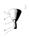
- Fig. 2 shows an exterior view of a rocket engine in scale representation. It is shown the combustion chamber 1, which is surrounded by a combustion chamber jacket 5 a, which also covers the directly adjacent expansion nozzle 2. The expansion nozzle 2 is followed by a thrust nozzle 8 surrounded by a nozzle jacket 5b. Combustion chamber 1 and expansion nozzle 2 on the one hand and the exhaust nozzle 8 on the other hand are formed in this case by a respective separate base body, wherein at least the main body of the combustion chamber 1 and expansion nozzle 2 consists of individual Strukturkörpem as segment body.
- FIG. 3 are individual structural body 4a, 4b, 4c shown, of which the combustion chamber 1 and the expansion nozzle 2 composed. It can be clearly seen that the here as three equally sized and identically shaped items trained integral structural body 4a, 4b, 4c already carry the structural features of both the combustion chamber 1 and the expansion nozzle 2:
- These structural body 4a, 4b, 4c can be made by clamping a blank in a jig by milling, with several milling steps can be followed each other , It can first be a pre-milling of the outer contour and the inner contour of the structural body 4a, 4b, 4c followed by a finer milling step, in which additional structures such as cooling channels 3 on the outside and / or internal structures 7 such as longitudinal grooves and / or transverse grooves or ribs can be formed on the inside of the structural body 4a, 4b, 4c.
- Fig. 4 shows the assembled rocket engine with combustion chamber 1 and expansion nozzle 2, wherein the segment body 4a, 4b, 4c along cut lines 6a, 6b, 6c, which extend in the longitudinal direction of the rocket engine, are joined together.
- the segment bodies 4a, 4b, 4c can be connected to each other either directly by soldering, but it can also be provided that the connection of the segment body 4a, 4b, 4c takes place only by a sheath 5, the outside on the segment body 4a, 4b, 4c is applied.
- a sheath 5 is in Fig. 1 shown schematically.
- Fig. 4b shows such a shell 5a, which surrounds the combustion chamber 1 and the expansion nozzle 2.
- the sheathing 5a shows the corresponding arrangement without sheathing 5a, so that the cooling channels 3 are still exposed on the outside.
- the sheathing 5a covers the cooling channels 3 mounted on the outer side of the segment bodies 4a, 4b, 4c, so that they then exist as channels which are closed on all sides and open only at the ends in the longitudinal direction.
- the sheath 5 or 5a can be applied, for example, by electroplating. To prevent clogging of the cooling channels 3 by the electrodeposition, they are previously filled with wax. After the deposition of the sheath 5, 5 a, the wax can be melted and thus flow out of the cooling channels 3, whereby the wax is removed from the cooling channels 3.
- Analogous measures are basically also applicable to a jacket 5b of the exhaust nozzle 8.
Landscapes
- Engineering & Computer Science (AREA)
- Mechanical Engineering (AREA)
- Chemical & Material Sciences (AREA)
- Combustion & Propulsion (AREA)
- General Engineering & Computer Science (AREA)
- Testing Of Engines (AREA)
- Toys (AREA)
Description
- Die vorliegende Erfindung betrifft ein Raketentriebwerk in Segmentbauweise, d. h. es werden zumindest Teile des Raketentriebwerkes aus einzelnen Segmenten aufgebaut, die dann zu einer vollständigen Anordnung zusammengefügt werden.
- Solche Raketentriebwerke sind aus dem Stand der Technik grundsätzlich bekannt. So zeigen
US 5,032,201 undEP 0 561 537 Raketentriebwerke, bei denen ein Brennkammerraum von einer in Längsrichtung des Raketentriebwerkes segmentierten Ummantelung umgeben ist. Bei solchen Triebwerken ist jedoch ein relativ hoher Aufwand nötig, um ein Zusammenfügen der kompletten Struktur des Raketentriebwerkes zu ermöglichen und eine sichere und stabile Verbindung der einzelnen Komponenten des Raketentriebwerkes zu garantieren. Auch können die übrigen Komponenten des Raketentriebwerkes wie z. B. die Expansionsdüse nur durch aufwendige Verfahren hergestellt werden. -
US 3,190,070 undUS 3,690,103 offenbaren Brennkammern mit angrenzenden Expansionsdüsen bei denen Röhrchen mit unterschiedlichster Geometrie entlang der Längsrichtung des Triebwerks aneinandergefügt werden und somit eine geschlossene Wandung bilden. So entsteht die Brennkammer und die Expansionsdüse und erhält gleichzeitig Kühlkanäle zum Durchfluss eines Kühlmittels. Da jedoch Kühlkanäle mit kleinem Durchmesser erwünscht sind, müssen sehr viele Röhrchen in Längsrichtung verbaut werden, was sehr aufwendig ist und wobei durch die vielen Übergänge viele Kontaktstellen entstehen, an denen eine Undichtigkeit auftreten kann. - Die
US 3,595,025 beschreibt eine Brennkammerkonstruktion eines Raketentriebwerks, die eine innere Wandung mit an deren Außenseite sich longitudinal erstreckenden Kühlkanälen aufweist. Ferner ist eine äußere Wandung vorgesehen, die durch Galvanisieren auf die innere Wandung aufgebracht ist. Sowohl die innere als auch die äußere Wandung sind aus einem einzigen Stück Sauerstofffreien Kupfers oder äquivalenten Materials wie Silber oder Molybdän gefertigt. - Die
WO 00/32920 - Aufgabe der vorliegenden Erfindung ist es daher, ein Raketentriebwerk und ein Herstellungsverfahren dafür bereitzustellen, das eine vereinfachte Herstellung von Raketentriebwerken erlaubt und das eine sichere und stabile Verbindung von Komponenten des Raketentriebwerkes garantiert.
- Diese Aufgabe wird gelöst durch die Merkmale der Patentansprüche 1 und 7.
- Das erfindungsgemäße Verfahren zur Herstellung eines Raketentriebwerkes dient zur Herstellung eines Raketentriebwerkes mit einer Brennkammer und einer an die Brennkammer angrenzenden Expansionsdüse. Es werden nun mindestens zwei einteilige Segmentkörper hergestellt, wobei jeder Segmentkörper Teilkonturen der Brennkammer und der Expansionsdüse bildet. Somit stellen die Segmentkörper Einzelbausteine der späteren Struktur aus Brennkammer und Expansionsdüse dar. Die Segmentkörper werden zur Bildung der Brennkammer und der Expansionsdüse zusammengefügt, wobei aber vor dem Zusammenfügen in jeder der Segmentkörper mehrere Kühlkanäle und/oder Rippen ein- bzw. aufgebracht werden. Die Segmentkörper können dabei gleich groß oder auch unterschiedlich groß sein, wobei die Herstellung gleich großer Segmentkörper (Hälften, Drittel, Viertel oder ähnliches) das Herstellungsverfahren vereinfacht.
- Somit kann in einem gemeinsamen Arbeitsgang die Brennkammer und die Expansionsdüse gebildet werden. Die Herstellung von Segmentkörpern kann außerdem leichter erfolgen als die Herstellung eines einstückigen Brennkammer- bzw. Expansionsdüsen-Hohlkörpers, da bei Segmentkörpern die Innen- und Außenflächen der Körper für eine Strukturierung der Segmentkörper und damit effektiv auch für eine Strukturierung der Brennkammer und Expansionsdüse leichter zugänglich sind. Somit können die Maße der Brennkammer und Expansionsdüse exakter eingestellt und auch vermessen werden. Für die Strukturierung können auch einfacher zu beherrschende Verfahren verwendet werden wie z. B. Fräsen.
- Das Verbinden der Segmentkörper kann durch jedes geeignete Verfahren erfolgen. Insbesondere kann vorgesehen werden, dass die Segmentkörper direkt miteinander verbunden werden, insbesondere können sie durch Verlöten oder Verschweißen miteinander verbunden werden. Alternativ oder zusätzlich können die Segmentkörper durch Aufbringen einer Ummantelung miteinander verbunden werden. Diese Ummantelung kann durch das Aufbringen vorgeformter Teile aufgebracht werden, oder sie kann auch durch einen Abscheidungsprozess, z. B. einen Galvanikprozess, aufgebracht werden.
- Es können, wie bereits erwähnt, auf einfache Weise Strukturierungen der Segmentkörper vorgenommen werden. Einerseits kann dadurch die Struktur der Brennkammer und der Expansionsdüse gezielt herausgebildet werden, andererseits können auch zusätzlich Strukturierungen wie z. B. Kühlkanäle oder Rippen in den Segmentkörpern geformt werden, die im späteren Betrieb des Raketentriebwerkes benötigt werden. Diese zusätzlichen Strukturen können, ebenso wie die Gesamtstruktur der Segmentkörper, durch geeignete, in der Regel einfacher zu beherrschende Verfahren hergestellt werden, z. B. durch Fräsen.
- Die Erfindung umfasst außerdem ein Raketentriebwerk mit einer Brennkammer und einer an die Brennkammer angrenzenden Expansionsdüse, wobei die Brennkammer und die Expansionsdüse aus mindestens zwei einteiligen Segmentkörpern aufgebaut sind, wobei jeder Segmentkörper Teilkonturen der Brennkammer und der Expansionsdüse bildet und jeder Segmentkörper mehrere Kühlkanäle und/oder Rippen aufweist. Die Segmentkörper können, wie bereits erwähnt, gleich oder verschieden groß sein.
- Vorteilhaft kann die Brennkammer und die Expansionsdüse in Längsrichtung des Raketentriebwerkes in Segmentkörper unterteilt sein, d. h. die Segmentkörper sind entlang von Schnittlinien miteinander verbunden, die in Längsrichtung des Raketentriebwerkes verlaufen. Solche Strukturen lassen sich leicht zusammenfügen und sind im zusammengefügten Zustand trotzdem stabil. Prinzipiell könnte auch eine gewisse Verzahnung der Segmentkörper entlang der Schnittlinien vorgesehen werden. Die Verbindung der Segmentkörper kann unterschiedlich ausgestaltet sein. Beispielsweise können die Segmentkörper miteinander verlötet sein oder durch eine Ummantelung miteinander verbunden sein.
- Ein spezielles Ausführungsbeispiel der vorliegenden Erfindung wird nachfolgend anhand der
Figuren 1 bis 3 erläutert. - Es zeigen:
- Fig. 1:
- Querschnitt durch ein Raketentriebwerk mit Brennkammer und Expansionsdüse
- Fig. 2:
- Außenansicht von Brennkammer, Expansionsdüse und Schubdüse eines Raketentriebwerks
- Fig. 3:
- Darstellung von Segmentkörpern
- Fig. 4:
- Darstellung der Brennkammer mit Expansionsdüse, aufgebaut aus Segmentkörpern
- Durch die erfindungsgemäße Lösung wird es entbehrlich, für Raketentriebwerke Brennkammern und Expansionsdüsen durch die Bearbeitung von rotationssymmetrischen Körpern herzustellen, um die notwendigen Hohlkörperstrukturen zu erzeugen. In
Fig. 1 ist ein solches Raketentriebwerk schematisch im Querschnitt dargestellt. Es weist eine Brennkammer 1 auf, an die im Bereich einer Verengung der Gesamtstruktur die Expansionsdüse 2 angrenzt. -
Fig. 2 zeigt eine Außenansicht eines Raketentriebwerks in mäßstabsgetreuer Darstellung. Es ist dabei die Brennkammer 1 dargestellt, die von einem Brennkammermantel 5a umgeben, der auch die direkt angrenzende Expansionsdüse 2 bedeckt. An die Expansionsdüse 2 schließt sich eine von einem Düsenmantel 5b umgebene Schubdüse 8 an. Brennkammer 1 und Expansionsdüse 2 einerseits sowie die Schubdüse 8 andererseits werden in diesem Fall durch je einen separaten Grundkörper gebildet, wobei zumindest der Grundkörper von Brennkammer 1 und Expansionsdüse 2 aus einzelnen Strukturkörpem als Segmentkörper besteht. - In
Fig. 3 sind einzelne Strukturkörper 4a, 4b, 4c dargestellt, aus denen sich die Brennkammer 1 und die Expansionsdüse 2 zusammensetzen. Es ist deutlich erkennbar, dass die hier als drei gleich große und gleich geformte Einzelteile ausgebildeten einstückigen Strukturkörper 4a, 4b, 4c bereits die Strukturmerkmale sowohl der Brennkammer 1 als auch der Expansionsdüse 2 tragen: Diese Strukturkörper 4a, 4b, 4c können nach einem Einspannen eines Rohlings in eine Spannvorrichtung, durch Fräsen hergestellt werden, wobei mehrere Frässchritte einander nachgeschaltet werden können. Es kann zunächst ein Vorfräsen der Außenkontur sowie der Innenkontur des Strukturkörper 4a, 4b, 4c erfolgen, gefolgt von einem feineren Frässchritt, in dem auch zusätzliche Strukturen wie Kühlkanäle 3 auf der Außenseite und/oder Innenstrukturen 7 wie beispielsweise Längsrillen und/oder Querrillen oder Rippen auf der Innenseite der Strukturkörper 4a, 4b, 4c geformt werden können. -
Fig. 4 zeigt das zusammengefügte Raketentriebwerk mit Brennkammer 1 und Expansionsdüse 2, wobei die Segmentkörper 4a, 4b, 4c entlang von Schnittlinien 6a, 6b, 6c, die in Längsrichtung des Raketentriebwerkes verlaufen, zusammengefügt sind. Die Segmentkörper 4a, 4b, 4c können entweder direkt durch Löten miteinander verbunden werden, es kann aber auch vorgesehen werden, dass die Verbindung der Segmentkörper 4a, 4b, 4c erst durch eine Ummantelung 5 erfolgt, die außen auf die Segmentkörper 4a, 4b, 4c aufgebracht wird. Eine solche Ummantelung 5 ist inFig. 1 schematisch dargestellt. AuchFig. 4b ) zeigt eine solche Ummantelung 5a, die die Brennkammer 1 und die Expansionsdüse 2 umgibt.Fig. 4a ) zeigt dagegen die entsprechende Anordnung ohne Ummantelung 5a, so dass die Kühlkanäle 3 auf der Außenseite noch frei liegen. Die Ummantelung 5a deckt dann die auf der Außenseite der Segmentkörper 4a,4b, 4c angebrachten Kühlkanäle 3 ab, so dass diese dann als allseitig geschlossene, nur noch an den Enden in Längsrichtung offene Kanäle vorliegen. Die Ummantelung 5 bzw. 5a kann beispielsweise galvanisch aufgebracht werden. Um ein Verstopfen der Kühlkanäle 3 durch die galvanische Abscheidung zu verhindern, werden diese vorher mit Wachs ausgefüllt. Nach erfolgter Abscheidung der Ummantelung 5, 5a kann das Wachs aufgeschmolzen werden und somit aus den Kühlkanälen 3 ausfließen, wodurch das Wachs aus den Kühlkanälen 3 entfernt wird. Analoge Maßnahmen sind grundsätzlich auch für eine Ummantelung 5b der Schubdüse 8 anwendbar.
Claims (9)
- Verfahren zur Herstellung eines eine Brennkammer (1) und eine an die Brennkammer (1) angrenzende Expansionsdüse (2) aufweisenden und in Längsrichtung in Segmentkörper unterteilten Raketentriebwerkes aus mindestens zwei einteiligen Segmentkörpern (4a, 4b, 4c), wobei jeder Segmentkörper (4a, 4b, 4c) Teilkonturen der Brennkammer (1) und der Expansionsdüse (2) bildet und die Segmentkörper (4a, 4b, 4c) zur Bildung der Brennkammer (1) und der Expansionsdüse (2) zusammengefügt werden, dadurch gekennzeichnet, dass vor dem Zusammenfügen der Segmentkörper (4a, 4b, 4c) mehrere Kühlkanäle (3) und/oder Rippen in jedem Segmentkörper (4a, 4b, 4c) geformt werden.
- Verfahren nach Anspruch 1, dadurch gekennzeichnet, dass die Kühlkanäle (3) durch Fräsen geformt werden.
- Verfahren nach Anspruch 1 oder 2, dadurch gekennzeichnet, dass die Segmentkörper (4a, 4b, 4c) direkt miteinander, insbesondere durch Verlöten oder Verschweißen, verbunden werden.
- Verfahren nach einem der Ansprüche 1 bis 3, dadurch gekennzeichnet, dass die Segmentkörper (4a, 4b, 4c) durch Aufbringen einer Ummantelung (5) miteinander verbunden werden.
- Verfahren nach Anspruch 4, dadurch gekennzeichnet, dass die Ummantelung (5) galvanisch aufgebracht wird.
- Verfahren nach einem der Ansprüche 1 bis 5, dadurch gekennzeichnet, dass die Segmentkörper (4a, 4b, 4c) durch Fräsen hergestellt werden.
- Raketentriebwerk aus einer Brennkammer (1) und einer an die Brennkammer (1) angrenzenden Expansionsdüse (2), wobei die Brennkammer (1) und die Expansionsdüse (2) in Längsrichtung des Raketentriebwerkes in Segmentkörper unterteilt sind und aus mindestens zwei einteiligen Segmentkörpern (4a, 4b, 4c) aufgebaut sind und jeder Segmentkörper (4a, 4b, 4c) Teilkonturen der Brennkammer (1) und der Expansionsdüse (2) bildet, dadurch gekennzeichnet, dass jeder Segmentkörper mehrere Kühlkanäle (3) und/oder Rippen aufweist.
- Raketentriebwerk nach Anspruch 7, dadurch gekennzeichnet, dass die Segmentkörper (4a, 4b, 4c) miteinander verlötet sind.
- Raketentriebwerk nach Anspruch 7, dadurch gekennzeichnet, dass die Segmentkörper (4a, 4b, 4c) durch eine Ummantelung (5) miteinander verbunden sind.
Applications Claiming Priority (3)
| Application Number | Priority Date | Filing Date | Title |
|---|---|---|---|
| DE10043303 | 2000-09-02 | ||
| DE10043303A DE10043303B4 (de) | 2000-09-02 | 2000-09-02 | Raketentriebwerk in Segmentbauweise |
| PCT/EP2001/009775 WO2002018772A1 (de) | 2000-09-02 | 2001-08-24 | Raketentriebwerk in segmentbauweise und verfahren zu seiner herstellung |
Publications (2)
| Publication Number | Publication Date |
|---|---|
| EP1313938A1 EP1313938A1 (de) | 2003-05-28 |
| EP1313938B1 true EP1313938B1 (de) | 2014-10-01 |
Family
ID=7654770
Family Applications (1)
| Application Number | Title | Priority Date | Filing Date |
|---|---|---|---|
| EP01971960.8A Expired - Lifetime EP1313938B1 (de) | 2000-09-02 | 2001-08-24 | Raketentriebwerk in segmentbauweise und verfahren zu seiner herstellung |
Country Status (4)
| Country | Link |
|---|---|
| EP (1) | EP1313938B1 (de) |
| AU (1) | AU2001291795A1 (de) |
| DE (1) | DE10043303B4 (de) |
| WO (1) | WO2002018772A1 (de) |
Cited By (1)
| Publication number | Priority date | Publication date | Assignee | Title |
|---|---|---|---|---|
| CN105479103A (zh) * | 2015-11-30 | 2016-04-13 | 湖北三江航天江北机械工程有限公司 | 薄壁花瓶状冷却室的加工方法 |
Families Citing this family (6)
| Publication number | Priority date | Publication date | Assignee | Title |
|---|---|---|---|---|
| DE102008011502A1 (de) | 2008-02-25 | 2009-09-03 | Deutsches Zentrum für Luft- und Raumfahrt e.V. | Düsenerweiterung und Verfahren zur Herstellung einer Düsenerweiterung |
| DE102008020198B8 (de) * | 2008-04-15 | 2015-05-13 | Astrium Gmbh | Düsenerweiterung für ein Triebwerk und Verfahren zur Herstellung und Kühlung einer Düsenerweiterung |
| EP2839905A1 (de) * | 2013-08-22 | 2015-02-25 | Astrium GmbH | Herstellung von Teilen aus verschiedenen Materialien, insbesondere für Raumtransportkomponenten wie Brennkammern für Triebwerke |
| CN103586636B (zh) * | 2013-11-11 | 2016-01-06 | 中国南方航空工业(集团)有限公司 | 喷口的加工方法及喷口的加工装置 |
| CN111375690B (zh) * | 2018-12-27 | 2022-04-12 | 航天海鹰(哈尔滨)钛业有限公司 | 一种钛合金变曲率双向应力结构钣金件的热压成形方法 |
| US12383975B2 (en) * | 2023-08-03 | 2025-08-12 | Blue Origin Manufacturing, LLC | Friction stir additive manufacturing formed parts and structures with integrated passages |
Family Cites Families (11)
| Publication number | Priority date | Publication date | Assignee | Title |
|---|---|---|---|---|
| US3190070A (en) * | 1950-04-05 | 1965-06-22 | Thiokol Chemical Corp | Reaction motor construction |
| US3451222A (en) * | 1965-10-08 | 1969-06-24 | Curtiss Wright Corp | Spray-cooled rocket engine |
| GB1192637A (en) * | 1966-09-24 | 1970-05-20 | Bolkow Ges Mil Beschrankter Ha | Cooling Tubes for the Walls of Combustion Chambers |
| DE1264160B (de) * | 1966-12-15 | 1968-03-21 | Boelkow Gmbh | Fluessigkeitsgekuehlte Bauteile, wie Raketenbrennkammern, und Verfahren zu deren Herstellung |
| FR2012723A1 (de) * | 1968-07-11 | 1970-03-20 | Messerschmitt Boelkow Blohm | |
| FR2606082B1 (fr) * | 1986-11-05 | 1991-04-05 | Europ Propulsion | Chambre de combustion de propulseur a propergol solide, et procede pour sa fabrication |
| DE3730011A1 (de) * | 1987-09-08 | 1989-04-27 | Michael Schenk | Bauteil mit wenigstens einem hohlraum, insbesondere einem stroemungskanal und verfahren zu seiner herstellung |
| US5341638A (en) * | 1992-03-09 | 1994-08-30 | Thiokol Corporation | Low cost segmented structure for pressure vessels, rocket motors, piping |
| US5799394A (en) * | 1996-02-05 | 1998-09-01 | Rice; Jose Luis | Method of making a marine speed nozzle |
| WO2000032920A1 (en) * | 1998-11-27 | 2000-06-08 | Volvo Aero Corporation | Nozzle structure for rocket nozzles having cooled nozzle wall |
| US6131280A (en) * | 1998-11-30 | 2000-10-17 | United Technologies Corporation | Method of repairing a rocket thrust chamber |
-
2000
- 2000-09-02 DE DE10043303A patent/DE10043303B4/de not_active Expired - Fee Related
-
2001
- 2001-08-24 EP EP01971960.8A patent/EP1313938B1/de not_active Expired - Lifetime
- 2001-08-24 AU AU2001291795A patent/AU2001291795A1/en not_active Abandoned
- 2001-08-24 WO PCT/EP2001/009775 patent/WO2002018772A1/de not_active Ceased
Cited By (1)
| Publication number | Priority date | Publication date | Assignee | Title |
|---|---|---|---|---|
| CN105479103A (zh) * | 2015-11-30 | 2016-04-13 | 湖北三江航天江北机械工程有限公司 | 薄壁花瓶状冷却室的加工方法 |
Also Published As
| Publication number | Publication date |
|---|---|
| DE10043303B4 (de) | 2004-06-09 |
| EP1313938A1 (de) | 2003-05-28 |
| WO2002018772A1 (de) | 2002-03-07 |
| AU2001291795A1 (en) | 2002-03-13 |
| DE10043303A1 (de) | 2002-03-21 |
| WO2002018772B1 (de) | 2002-06-06 |
| WO2002018772A8 (de) | 2002-09-26 |
Similar Documents
| Publication | Publication Date | Title |
|---|---|---|
| DE60221284T2 (de) | Bauteil zur beaufschlagung mit hoher thermischer belastung beim betrieb und verfahren zur herstellung eines solchen bauteils | |
| EP1098725B1 (de) | Verfahren und vorrichtung zur herstellung eines metallischen hohlkörpers | |
| DE69815901T2 (de) | Düsenstruktur für raketendüsen mit gekühlten düsenwänden | |
| EP1668236B1 (de) | Brennkammer mit kühleinrichtung und verfahren zur herstellung der brennkammer | |
| DE69923099T2 (de) | Produktionsweise für einen regenerativen Wärmetauschkreislauf für hohen Wärmefluss, insbesondere für Raketenbrennkammern | |
| DE2245599A1 (de) | Reibgeschweisster metallgegenstand und verfahren zu seiner herstellung | |
| EP1247602B1 (de) | Verfahren zur Herstellung einer Turbinenschaufel | |
| DE3307791A1 (de) | Komposit-bauteil und verfahren zu dessen herstellung | |
| EP2511030A2 (de) | Verfahren zum Herstellen eines Bauteils mit wenigstens einem in dem Bauteil angeordneten Bauelement, sowie ein Bauteil mit wenigstens einem Bauelement | |
| EP0660064A2 (de) | Rohr-Bodenverbindung für einen Wärmetauscher | |
| DE69908739T2 (de) | Verfahren zur Herstellung eines Raketenschubrohres | |
| DE60313979T2 (de) | Verfahren zur herstellung einer statorkomponente | |
| EP0947666B1 (de) | Gebauter Leitkranz für ein Gasturbinentriebwerk, sowie Verfahren zu seiner Herstellung | |
| DE10043303B4 (de) | Raketentriebwerk in Segmentbauweise | |
| DE2502631A1 (de) | Gehaeuse fuer ein gekuehltes einteiliges ventil in brennkraftmaschinen | |
| DE102008023052A1 (de) | Brennkammerwand bzw. Heißgaswand einer Brennkammer und Brennkammer mit einer Brennkammerwand | |
| DE102004043166A1 (de) | Intravaskulärer Stent und Verfahren zu seiner Herstellung | |
| EP1049549B1 (de) | Giessvorrichtung mit gussform und einem positionierungselement | |
| DE102014106244B4 (de) | Gegossene Komponente mit statischer Kernverankerung | |
| DE69916786T2 (de) | Verfahren zum Herstellen von einem Gaserzeuger eines geschweissten und gelöteten Bauteiles | |
| DE2262619A1 (de) | Mehreckiger kolben fuer kreiskolbenbrennkraftmaschinen und verfahren zu seiner herstellung | |
| EP3538315B1 (de) | Verfahren zur herstellung eines hohlraums in einer schaufelplattform ; entsprechender schaufel | |
| DE4123029A1 (de) | Kolben | |
| DE3807055A1 (de) | Verfahren zur herstellung eines waermetauscherblockes sowie vorrichtung zur durchfuehrung des verfahrens | |
| DE3706260A1 (de) | Turbomaschinenschaufel mit oberflaechennahen kuehlkanaelen und verfahren zu ihrer herstellung |
Legal Events
| Date | Code | Title | Description |
|---|---|---|---|
| PUAI | Public reference made under article 153(3) epc to a published international application that has entered the european phase |
Free format text: ORIGINAL CODE: 0009012 |
|
| 17P | Request for examination filed |
Effective date: 20030313 |
|
| AK | Designated contracting states |
Designated state(s): AT BE CH CY DE DK ES FI FR GB GR IE IT LI LU MC NL PT SE TR |
|
| AX | Request for extension of the european patent |
Extension state: AL LT LV MK RO SI |
|
| RBV | Designated contracting states (corrected) |
Designated state(s): FR IT |
|
| REG | Reference to a national code |
Ref country code: DE Ref legal event code: 8566 |
|
| RAP1 | Party data changed (applicant data changed or rights of an application transferred) |
Owner name: EADS SPACE TRANSPORTATION GMBH |
|
| 17Q | First examination report despatched |
Effective date: 20070709 |
|
| RIC1 | Information provided on ipc code assigned before grant |
Ipc: F02K 9/34 20060101AFI20130930BHEP Ipc: B23K 31/02 20060101ALI20130930BHEP Ipc: F02K 9/97 20060101ALI20130930BHEP Ipc: F02K 9/62 20060101ALI20130930BHEP Ipc: B23P 15/00 20060101ALI20130930BHEP |
|
| GRAP | Despatch of communication of intention to grant a patent |
Free format text: ORIGINAL CODE: EPIDOSNIGR1 |
|
| INTG | Intention to grant announced |
Effective date: 20131120 |
|
| GRAS | Grant fee paid |
Free format text: ORIGINAL CODE: EPIDOSNIGR3 |
|
| RAP1 | Party data changed (applicant data changed or rights of an application transferred) |
Owner name: ASTRIUM GMBH |
|
| GRAA | (expected) grant |
Free format text: ORIGINAL CODE: 0009210 |
|
| AK | Designated contracting states |
Kind code of ref document: B1 Designated state(s): FR IT |
|
| RAP2 | Party data changed (patent owner data changed or rights of a patent transferred) |
Owner name: AIRBUS DS GMBH |
|
| PLBE | No opposition filed within time limit |
Free format text: ORIGINAL CODE: 0009261 |
|
| STAA | Information on the status of an ep patent application or granted ep patent |
Free format text: STATUS: NO OPPOSITION FILED WITHIN TIME LIMIT |
|
| REG | Reference to a national code |
Ref country code: FR Ref legal event code: PLFP Year of fee payment: 15 |
|
| 26N | No opposition filed |
Effective date: 20150702 |
|
| REG | Reference to a national code |
Ref country code: FR Ref legal event code: PLFP Year of fee payment: 16 |
|
| REG | Reference to a national code |
Ref country code: FR Ref legal event code: PLFP Year of fee payment: 17 |
|
| PGFP | Annual fee paid to national office [announced via postgrant information from national office to epo] |
Ref country code: IT Payment date: 20170828 Year of fee payment: 17 Ref country code: FR Payment date: 20170822 Year of fee payment: 17 |
|
| PG25 | Lapsed in a contracting state [announced via postgrant information from national office to epo] |
Ref country code: IT Free format text: LAPSE BECAUSE OF NON-PAYMENT OF DUE FEES Effective date: 20180824 |
|
| PG25 | Lapsed in a contracting state [announced via postgrant information from national office to epo] |
Ref country code: FR Free format text: LAPSE BECAUSE OF NON-PAYMENT OF DUE FEES Effective date: 20180831 |