EP1313216A2 - Temperature compensation mechanism for a micromechanical ring resonator - Google Patents
Temperature compensation mechanism for a micromechanical ring resonator Download PDFInfo
- Publication number
- EP1313216A2 EP1313216A2 EP02079955A EP02079955A EP1313216A2 EP 1313216 A2 EP1313216 A2 EP 1313216A2 EP 02079955 A EP02079955 A EP 02079955A EP 02079955 A EP02079955 A EP 02079955A EP 1313216 A2 EP1313216 A2 EP 1313216A2
- Authority
- EP
- European Patent Office
- Prior art keywords
- resonator
- oscillation
- substrate
- time base
- ring
- Prior art date
- Legal status (The legal status is an assumption and is not a legal conclusion. Google has not performed a legal analysis and makes no representation as to the accuracy of the status listed.)
- Granted
Links
Images


Classifications
-
- G—PHYSICS
- G01—MEASURING; TESTING
- G01C—MEASURING DISTANCES, LEVELS OR BEARINGS; SURVEYING; NAVIGATION; GYROSCOPIC INSTRUMENTS; PHOTOGRAMMETRY OR VIDEOGRAMMETRY
- G01C19/00—Gyroscopes; Turn-sensitive devices using vibrating masses; Turn-sensitive devices without moving masses; Measuring angular rate using gyroscopic effects
- G01C19/56—Turn-sensitive devices using vibrating masses, e.g. vibratory angular rate sensors based on Coriolis forces
- G01C19/5705—Turn-sensitive devices using vibrating masses, e.g. vibratory angular rate sensors based on Coriolis forces using masses driven in reciprocating rotary motion about an axis
- G01C19/5712—Turn-sensitive devices using vibrating masses, e.g. vibratory angular rate sensors based on Coriolis forces using masses driven in reciprocating rotary motion about an axis the devices involving a micromechanical structure
-
- H—ELECTRICITY
- H03—ELECTRONIC CIRCUITRY
- H03B—GENERATION OF OSCILLATIONS, DIRECTLY OR BY FREQUENCY-CHANGING, BY CIRCUITS EMPLOYING ACTIVE ELEMENTS WHICH OPERATE IN A NON-SWITCHING MANNER; GENERATION OF NOISE BY SUCH CIRCUITS
- H03B5/00—Generation of oscillations using amplifier with regenerative feedback from output to input
- H03B5/30—Generation of oscillations using amplifier with regenerative feedback from output to input with frequency-determining element being electromechanical resonator
Definitions
- the present invention relates to a time base, i.e. a device comprising a resonator and an integrated electronic circuit for driving the resonator into oscillation and for producing, in response to this oscillation, a signal having a determined frequency as well as to a resonator for use in such a time base.
- the present invention more particularly relates to a compensation mechanism for compensating for the effect of temperature on the resonant frequency of the resonator.
- Time bases are required in a large variety of electronic devices, ranging from wristwatches and other timepieces to complex telecommunication devices.
- Such time bases are typically formed by an oscillator including a quartz resonator and an electronic circuit for driving the resonator into oscillation.
- An additional division chain may be used to divide the frequency of the signal produced by the oscillator in order to obtain a lower frequency.
- Other parts of the circuit may serve to adjust the frequency, for example by adjusting the division ratio of the division chain.
- the components of the electronic circuit are advantageously integrated onto a single semiconductor substrate in CMOS technology. Other functions, not directly related to the frequency processing, may be integrated onto the same substrate.
- quartz resonators are their high quality factor Q leading to good frequency stability and low power consumption as well as their good temperature stability.
- a disadvantage of typical time bases using quartz resonators however resides in the fact that two components, namely the quartz resonator and the integrated electronic circuit, are required in order to provide a high-precision frequency.
- a discrete quartz resonator requires board space which is scarce in many cases.
- a standard quartz resonator for wristwatch applications requires space of the order of 2x2x6 mm 3 .
- additional costs are caused by the assembly and connection of the two components.
- space and assembly costs are major issues, especially in the growing field of portable electronic devices.
- a solution to the above-mentioned problems is to provide a time base comprising an integrated resonator.
- one solution consists in providing a time base comprising a resonator and an integrated circuit for driving the resonator into oscillation and for producing, in response to the oscillation, a signal having a determined frequency, the resonator being an integrated micromechanical ring resonator supported above a substrate and adapted to oscillate, according to a first oscillation mode, around an axis of rotation substantially perpendicular to the substrate, this ring resonator comprising :
- micromechanical ring resonator exhibits a high quality factor Q.
- Quality factors as high as 2x10 5 have been measured.
- tuning-fork quartz resonators usually exhibit values between 5x10 4 and 1x10 5 after laser trimming of the fork tines. Different design features favouring a high quality factor Q are proposed.
- the surface area required on the substrate to form the ring resonator is small in comparison with other resonators.
- the electronic circuit may advantageously be integrated on the substrate together with the micromechanical ring resonator, thereby leading to a low-priced time base.
- a lower price is also obtained by wafer-level packaging of the resonator using wafer-bonding technology.
- ring resonators having similar features are known from sensing devices, such as angular rate sensors, accelerometers or gyroscopes.
- sensing devices such as angular rate sensors, accelerometers or gyroscopes.
- U.S. Patent No. 5,450,751 to Putty et al. and U.S. Patent No. 5,547,093 to Sparks both disclose a micromechanical ring resonator for a vibratory gyroscope comprising a plated metal ring and spring system supported above a silicon substrate.
- U.S. Patent No. 5,872,313 to Zarabadi et al. discloses a variant of the above sensor which is configured to exhibit minimum sensitivity to temperature variation.
- U.S. Patent No. 5,025,346 also discloses a ring resonator for use as a micro-sensor in a gyroscope or an angular rate sensor.
- the resonant frequency of the ring resonator is, within the temperature range of 0 to 60°C, in good approximation, a linear function of temperature. At a resonant frequency of 45 kHz, it has been observed that the thermal coefficient of the resonant frequency is of the order of -25 ppm/°C.
- One solution to the above problem may consist in integrating a temperature measuring circuit on the substrate in order to compensate for the effect of temperature on the frequency of the signal produced by the time base. Such compensation of the resonator's temperature dependency may easily be effected since the above ring resonator has the advantage of exhibiting substantially linear temperature characteristics.
- Another solution to the above problem may consist in forming a second micromechanical ring resonator on the substrate in order to allow temperature compensation.
- An object of the present invention is to provide a mechanism for substantially compensating for the effect of temperature on the resonant frequency of the ring resonator which does not require an additional temperature measuring circuit or an additional resonator.
- a time base of the above-mentioned type as well as a method for driving the time base resonator into oscillation, wherein electrodes are positioned under the free-standing oscillating structure in such a way as to drive and sense a second oscillation mode in a plane substantially perpendicular to the substrate and having a resonant frequency which is different from the resonant frequency of the first oscillation mode, a frequency difference between the resonant frequencies of both oscillation modes being used for compensating for the effect of temperature on the frequency of the signal produced by the time base.
- temperature compensation is accordingly achieved by using a single micromechanical ring resonator which is operated simultaneously with two oscillation modes having different resonant frequencies.
- Figure 1 schematically shows a top view of a first embodiment of a time base.
- an integrated time base indicated generally by reference numeral 1, comprising a resonator 4 and an integrated electronic circuit 3 for driving the resonator into oscillation and for producing, in response to this oscillation, a signal having a determined frequency.
- Figure 4 shows a cross-sectional view of the ring resonator 4 taken along line A-A' as shown in Figure 1.
- the integrated electronic circuit 3 is not shown in detail since this circuit may easily be designed by those skilled in the art.
- both the integrated electronic circuit 3 and the resonator 4 are realized and integrated on a same substrate 2 as illustrated in Figure 1.
- a preferred substrate material is silicon, but other similar materials known by those skilled in the art to be equally suitable for realising the time base of the present invention may be used.
- the resonator 4 is realised in the form of a monolithic micromechanical resonating ring, hereinafter referred to as a micromechanical ring resonator, which is essentially supported above the substrate 2 and adapted to oscillate around an axis of rotation O substantially perpendicular to the substrate 2.
- the ring resonator 4 essentially comprises a central post 5 extending from the substrate 2 along the axis of rotation O and a free-standing oscillating structure, indicated globally by reference numeral 6, connected to the central post 5.
- the free-standing oscillating structure 6 includes an outer ring 60 coaxial with the axis of rotation O, and a plurality of spring elements 62 disposed symmetrically around the central post 5 and connecting the outer ring 60 to the central post 5.
- the spring elements 62 are essentially formed as curved rod-shaped spring elements. It will be appreciated that the central post 5 constitutes the only mechanical connection of the ring resonator 4 with the substrate 2 and that oscillation of the resonator takes place in a plane substantially parallel to the surface of the substrate 2.
- the ring resonator 4 further comprises pairs of diametrically opposed electrode structures surrounding the outer ring 60, indicated by reference numeral 9 in Figure 1.
- comb-shaped members 8 are provided on the outer ring 60 of the free-standing oscillating structure 6. These comb-shaped members 8 form a part of the electrode structures of the ring and each include a base member 80 extending radially from the outer ring 60 and first and second lateral members, indicated respectively by reference numerals 82 and 84, that extend substantially perpendicularly from both sides of the base member 80.
- the electrode structures 9 comprise first and second comb-shaped electrode structures 91 and 93 surrounding the outer ring 60 in such a way that they mesh with the comb-shaped members 8 of the free-standing oscillating structures. More particularly, according to this embodiment, the first comb-shaped electrode structure 91 includes first electrodes 92 and meshes with comb-shaped member 8 so that the first electrodes 92 are adjacent to the first lateral members 82. Similarly, the second comb-shaped electrode structure 93 (disposed opposite the first comb-shaped electrode structure 91) includes second electrodes 94 and meshes with comb-shaped member 8 so that the second electrodes 94 are adjacent to the second lateral members 84. As shown in Figure 1, the lateral members 82, 84 and the electrodes 92, 94 of the first and second electrode structures 91, 93 are preferably designed so as to have the shape of an arc of a circle concentric with the outer ring 60.
- the first comb-shaped electrode structures 91 serve to electrostatically drive the ring resonator 4 into oscillation
- the second comb-shaped electrode structure 93 which are disposed on the other side of the base members 80, serve to capacitively sense the oscillation of the resonator.
- the first electrode structures 91 surrounding the resonator 4 are connected together via a first conductor 11 formed on the substrate 2, and, similarly, the second electrode structures 93 are connected together via a second conductor 12 formed on the substrate 2.
- These conductors 11, 12 as well as a third conductor 13 providing an electrical contact to the ring via the central post 5 are connected to appropriate terminals of the electronic circuit 3.
- Figure 4 shows a cross-sectional view of the ring resonator 4 taken along line A-A' as illustrated in Figure 1. Thickness and other dimensions are not to scale. There is shown the substrate 2, the central post 5 along the axis of rotation O of the ring resonator, the free-standing oscillating structure 6 including the outer ring 60 and the spring elements 62, the lateral members 82 of the comb-shaped members 8, the electrodes 92 of the first comb-shaped electrode structures 91, and the first and second connectors 11, 12 that respectively connect the electrode structures 91 and 93 surrounding the outer ring 60.
- Figure 4 further shows a first insulating layer 20, such as a silicon oxide layer, formed above the surface of substrate 2, beneath the ring resonator 4 and onto which are formed the first and second conductors 11, 12.
- the resonating ring structure is preferably manufactured by means of silicon surface micro-machining techniques which are familiar to those skilled in the art and will therefore not be described here.
- silicon surface micro-machining techniques which are familiar to those skilled in the art and will therefore not be described here.
- One such technique makes use of a poly-silicon layer deposited on top of a so-called “sacrificial layer” in order to form the free-standing structures of the resonator.
- a buried oxide layer such as e.g. in a silicon on insulator (SOI) wafer, as the sacrificial layer and results in a free-standing structure made of mono-crystalline silicon.
- SOI silicon on insulator
- Other material and processing techniques may also be used to realise the micromechanical ring resonator according to the present invention.
- a high quality factor Q of the resonator results in a stable oscillation with low phase noise and low power consumption as is required for horological applications.
- the quality factor Q of the micromechanical ring resonator is very high due to a number of advantageous design features that will be explained below.
- quality factors as high as 2x10 5 have been measured on these structures.
- tuning-fork quartz resonators usually exhibit values between 5x10 4 and 1x10 5 after laser trimming of the fork tines.
- the shape of the spring elements 62 connecting the outer ring 60 to the central post 5 is optimised so as to obtain a high quality factor Q.
- the tensions along the bending line are, in the present case, homogeneously distributed along the spring element.
- the curved shape is such that energy losses per oscillation period are kept minimal.
- junctions 63 of the spring elements 62 with the central post 5 are substantially perpendicular, as shown in Figure 2.
- round shapes or fillets 63a are provided at the junctions 63.
- These fillets 63a prevent notch tensions during oscillation, thereby favouring an elevated quality factor Q, as substantially no energy is dissipated in the central post 5 during oscillation.
- the central post 5 remains substantially free of tension, which again favours a high quality factor Q.
- Figure 3 shows the junctions 64 of the spring elements 62 with outer ring 60.
- substantially perpendicular junctions 64 and fillets 64a are preferred designs.
- the quality factor Q increases with the number of spring elements.
- the upper limit is given by geometrical restrictions due to the design rules of the micro-structuring process.
- the number of spring elements is therefore comprised between four and fifty, and preferably is of the order of twenty.
- Another element favouring a high quality factor Q of the ring resonator is the perfect rotationally symmetrical structure, where the centre of gravity of the entire structure remains motionless. Non-linear effects, present in most other resonator designs, are thereby removed to a large extent.
- the resonant frequency of the ring resonator can be adjusted over a wide range by changing the geometrical dimensions of the device.
- the ring resonator can be looked at as a plurality of spring elements connected to a segment of the outer ring. In a zero-order approximation, and in order to obtain a close algebraic expression for the resonant frequency, one can study the case of a straight spring element 22 with a segment 27 of the outer ring 60, as shown in Figure 5.
- the resonant frequency f r of this structure reads : f r ⁇ 1 2 ⁇ 3 ⁇ E ⁇ J I 3 (m r + 0.24 ⁇ m s )
- J d w 3 / 12 is the surface moment of inertia of the structure
- E is the elasticity module
- d, w and / are the thickness, width and length of the straight spring element 22, respectively
- m r , m s are the masses of the ring segment 27 and spring element 22, respectively.
- the resonance frequency can be influenced by varying the width and/or length of the spring elements or by varying the mass of the outer ring (including the mass of the comb-shaped members 8), again via its geometrical dimensions. Scaling of the entire structure further widens the accessible frequency range.
- the surface area required by the micromechanical ring resonator is very small with respect to the resonant frequency obtained.
- a ring resonator designed for a rather low frequency of 32 kHz requires a surface of well below 1 mm 2 .
- Conventional structures require relatively large structures in order to obtain such a low frequency.
- the dimensions and frequency are inversely related, i.e. the larger the geometrical dimensions, the lower the frequency.
- EP 0 795 953 describes a silicon resonator requiring a surface of about 1.9 mm 2 for a higher frequency of 1 MHz. It is obvious that the substrate surface area required by the resonator is directly related to the price of the integrated time base.
- the resonant frequency of the ring resonator is, within the temperature range of 0 to 60°C, in good approximation, a linear function of temperature. At a resonant frequency of 45 kHz, it has been observed that the thermal coefficient of the resonant frequency is of the order of -25 ppm/°C. It is thus desirable to incorporate, in the same substrate 2, a temperature measuring circuit having an output signal which may be used to compensate for the frequency variation by adequately adjusting the frequency of the signal produced by the time base.
- the time base may advantageously comprise an integrated temperature measuring circuit (not shown).
- an integrated temperature measuring circuit is described in the article "Smart Temperature Sensor in CMOS Technology” by P. Krumenacher and H. Oguey, in “Sensors and Actuators", A21-A23 (1990), pages 636 to 638.
- temperature compensation is achieved by acting on the division ratio of the division chain, for instance using an inhibition technique well known to those skilled in the art.
- two ring resonators with different resonant frequencies may be integrated onto the same chip, such arrangement allowing the chip temperature to be precisely determined by measuring the frequency difference of the two resonators (both ring resonators have the same temperature coefficient since they are made from the same material).
- the advantage of using integrated time bases as described hereinabove is twofold: Firstly, the temperature dependency of the ring resonator is linear which facilitates the electronic signal treatment necessary to compensate for the temperature. Secondly and more importantly, the small size and monolithic integration of the ring resonator allows a second resonator to be provided with only a slight increase in chip size and without further external connections.
- a single ring resonator which operates simultaneously with two oscillation modes.
- a first of these modes is the above described rotational mode.
- a second oscillation mode may be a tilting oscillation mode, wherein the free-standing structure 6 performs a tilting oscillation against the substrate plane.
- This tilting oscillation mode may be excited electrostatically and sensed capacitively by using further electrodes on the substrate under the ring area.
- the two modes are selected to have different frequencies so that temperature compensation may be achieved by measuring the frequency difference.
- a schematic illustration of the above mentioned tilt mode is shown in Figures 11a and 11b.
- two sets of electrodes 100 and 120 (in this case four) having substantially the shape of arcs of circles are disposed on the substrate under the ring 60 so that the first set of electrodes 100 drives the structure 6 into a tilting oscillation and the second set of electrodes 120 senses this tilting oscillation.
- the set of driving electrodes 100 and the set of sensing electrodes 120 are disposed on opposite sides of the structure 6 with respect to the central post 5 (respectively on the left and right sides in Figure 11a).
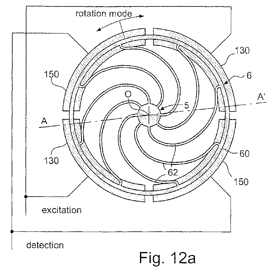
- a second oscillation mode may be a vertical oscillation mode, wherein the free-standing structure 6 performs a vertical oscillation perpendicular to the substrate plane, i.e. the free-standing structure 6 oscillates in a direction parallel to the axis of rotation O.
- a schematic illustration of the above mentioned perpendicular mode is shown in Figures 12a and 12b.
- two sets of electrodes 130 and 150 are disposed on the substrate under the ring 60 so that the first set of electrodes 130 drives the structures 6 into an oscillation perpendicular to the substrate plane and the second set of electrodes 150 senses this oscillation.
- the set of driving and sensing electrodes 130, 150 are disposed symmetrically around the central post 5, i.e. the sets of electrodes each comprise diametrically opposed electrodes.
- the comb-shaped electrode structures 91 shown in the embodiment of Figure 1 serve to electrostatically drive the ring resonator into oscillation and the opposite comb-shaped electrode structures 93 serve to capacitively sense this mechanical oscillation.
- An alternating voltage signal is applied to electrode structures 91 resulting in electrostatic forces on the ring and oscillation thereof, which, in turn, induces an alternating signal on the opposite set of electrode structures 93, when the resonator operates.
- electrode structures 91 and 93 are interchangeable.
- conductor 13 may be used to apply the direct voltage component to the ring resonator via the central post 5, while the alternating voltage component is applied to electrode structures 91 via conductor 11, conductor 12 being used to sense the resulting signal.
- the alternating driving voltage and the direct voltage component may be superposed on electrode structures 91 via conductor 11 while the ring resonator is tied to a fixed potential, such as e.g. ground, via conductor 13.
- Conductor 12 is used to sense the signal in this case. It will be appreciated that electrode structures 91 and 93 are interchangeable and that electrode structures 93 may alternatively be used for driving, electrode structures 91 being used for sensing.
- sensing may be done by detecting a change in impedance at resonance.
- a solution requires only two conductors, 11 and 13, and an electrode structure 9* comprising a single set of comb-shaped electrode structures 91 connected to conductor 11 (the comb-shaped members 8* are modified accordingly and only comprise first lateral members 82).
- the alternating driving voltage is applied, via conductor 11, to the single set of electrode structures 91, and the direct voltage component is applied to the ring via conductor 13.
- the sum of alternating and direct driving voltages can be applied to electrode structures 91 via conductor 11, the ring being in this case tied via conductor 13 to a fixed potential such as e.g. ground.
- the two-conductor option provides two advantages, namely (i) a reduction in the diameter of the entire structure since a second conductor and a second set of electrode structures surrounding the ring is no longer required, and (ii) the possibility of providing a larger number of comb-shaped electrode structures 91 along the periphery of the outer ring 60, resulting in an enhanced signal.
- Electrodes 91 Ring Electrodes 93 Remarks 3 Conductors AC-driving DC-bias Sensing Electrodes 91 and 93 are interchangeable AC-driving + DC bias Fixed potential, e.g. ground Sensing DC-bias AC-driving Sensing Fixed potential, e.g.
- the lateral members 82, 84 and the electrodes 92, 94 are of curved shape and concentric with outer ring 60 reduces non-linearities in the electromechanical coupling, resulting in a high quality factor Q on the one hand and a resonant frequency of the ring resonator which is essentially independent of the amplitude of alternating and direct driving voltages on the other hand.
- the micromechanical ring resonator can be driven with voltages as low as 1.5 V, which is a major advantage for portable electronic applications.
- the power consumption of the ring resonator is ten to hundred times lower than that of a quartz, which is of particular interest for portable electronics applications.
- Figures 7a to 7c show three different advantageous design features intended to prevent the ring resonator from sticking in case of a shock.
- stop structures 28 disposed on the substrate 2 are provided at outer ends 80a of the base members 80. These stop structures 28 are designed so as to limit the angular movement of the ring structure 6 and therefore prevent the free-standing oscillating structure 6 from sticking on the electrode structures 9 when excessive angular movements take place due, for instance, to mechanical shocks.
- extremities 82a, 84a of the lateral members 82, 84 and/or extremities 92a, 94a of the electrodes 92, 94 may be designed so as to exhibit a pointed shape or at least a suitably small surface area so as to prevent sticking.
- one 82*, 84* of the lateral members 82, 84 can be made longer than the others, thereby reducing the adhesion forces when the comb-shaped members 8 and the comb-shaped electrode structures 91, 93 get into mechanical contact with each other. Obviously, the same effect may be obtained when one of electrodes 92 and 94 is longer than the others.
- Figures 8 and 9 show an improvement of the micromechanical ring resonator 4 which is illustrated in Figure 1.
- Figure 9 shows a cross-sectional view of Figure 8 taken along line A-A'.
- a conductive pattern 31 is provided on (or below) the surface of the substrate 2 under at least part of the free-standing oscillating structure 6, i.e. spring elements 62, outer ring 60, as well as comb-shaped members 8, the shape of this conductive pattern 31 being essentially a projection of the free-standing oscillating structure 6 on the surface of the substrate 2.
- Figures 10a and 10b show further improvements of the micromechanical ring resonator 4 which allow the temperature coefficient of the resonant frequency to be reduced to a value close to zero.
- Two main factors determine the temperature characteristics of the ring resonator. Firstly, Young's modulus E of the material used to realize the vibrating structure decreases with increasing temperature resulting in a reduced stiffness of the spring elements 62 and therefore a lower resonant frequency. Secondly, due to thermal expansion, the diameter of the ring will increase with increasing temperature resulting in an increased mass moment of inertia of the structure, which, in turn, also reduces the resonant frequency.
- a compensation mechanism 65 As sketched in Figure 10a or 10b.
- a plurality of thermally compensating members 65 are attached to the outer ring 60.
- These thermally compensating members 65 are designed to alter the mass moment of inertia of the free-standing oscillating structure 6 as a function of temperature so as to substantially compensate for the effect of temperature on the resonant frequency of the resonator 4.
- the members 65 include a weight member 66 connected to the outer ring 60 by means of a connecting member 67 comprising first and second layers 68, 69 made respectively of first and second materials having different thermal coefficients.
- the materials are chosen so that the thermal expansion coefficient ⁇ th1 of the first layer 68 is smaller than the thermal expansion coefficient ⁇ th2 of the second layer 69.
- the first material is silicon and the second material is a metal, preferably aluminium.
- the design of the mechanism 65 according to Figure 10a is such that, with increasing temperature, the connecting member 67 straightens due to the different thermal expansion of the first and second layers 68, 69. As a consequence, the weight members 66 move towards the centre of the ring, i.e. closer to the axis of rotation O of the oscillating structure 6, thereby reducing the mass moment of inertia of the ring resonator, resulting in an increase of the resonant frequency which substantially counteracts the effect of the Young's modulus and the thermal expansion of the ring on the resonant frequency.
- thermal compensation mechanisms can alternatively be attached to the outer side of the ring 60, as shown in Figure 10b, or to some other part of the free-standing oscillating structure 6 so as to alter its mass moment of inertia as a function of temperature.
- the layout and fabrication of the members 65 have to be realized so that the weight members 66 move towards the axis of rotation O of the ring resonator when temperature increases.
Landscapes
- Physics & Mathematics (AREA)
- Engineering & Computer Science (AREA)
- General Physics & Mathematics (AREA)
- Radar, Positioning & Navigation (AREA)
- Remote Sensing (AREA)
- Micromachines (AREA)
- Oscillators With Electromechanical Resonators (AREA)
- Piezo-Electric Or Mechanical Vibrators, Or Delay Or Filter Circuits (AREA)
- Electric Clocks (AREA)
- Gyroscopes (AREA)
- Inductance-Capacitance Distribution Constants And Capacitance-Resistance Oscillators (AREA)
- Measuring Fluid Pressure (AREA)
Abstract
Description
- a central post extending from the substrate along the axis of rotation ;
- a free-standing oscillating structure connected to the central post and including an outer ring coaxial with the axis of rotation and connected to the central post by means of a plurality of spring elements ; and
- electrode structures disposed around the outer ring and connected to the integrated electronic circuit. Advantages on this solution reside in the fact that the time base may be fully integrated on a single substrate, is suitable for mass production and is compatible with CMOS technology. In addition, such a time base is low-priced and requires only a very small surface area on a semiconductor chip.
- Figure 1 is a top view illustrating schematically a first embodiment of a time base comprising a micromechanical ring resonator and an integrated electronic circuit;
- Figure 2 is a detailed view of the central post of the micromechanical ring resonator and its junctions with the spring elements;
- Figure 3 is a detailed view of a portion of the outer ring with its junctions with the spring elements;
- Figure 4 is a cross-sectional view of the micromechanical ring resonator of Figure 1 taken along line A-A';
- Figure 5 shows an idealized straight spring element with a section of the outer ring;
- Figure 6 shows a top view illustrating schematically a second embodiment of a time base;
- Figures 7a to 7c show detailed top views of three different designs intended to prevent the ring resonator from sticking on the electrode structures;
- Figure 8 shows a top view illustrating an improvement of the first embodiment shown in Figure 1;
- Figure 9 is a cross-sectional view of the embodiment of Figure 8 taken along line A-A';
- Figures 10a and 10b are two top views illustrating two variants of a mechanism for altering the mass moment of inertia of the ring resonator as a function of temperature, in order to substantially compensate for the effect of temperature on the resonant frequency of the ring resonator;
- Figures 11a and 11b are respectively top and cross-sectional views illustrating a second mode of oscillation where the resonator performs a tilting oscillation; and
- Figures 12a and 12b are respectively top and cross-sectional views illustrating another second mode of oscillation where the resonator performs a vertical oscillation perpendicular to the substrate plane.
| | | Electrodes | 93 | | ||
| 3 Conductors | AC-driving | DC- | Sensing | Electrodes | 91 and 93 are interchangeable | |
| AC-driving + DC bias | Fixed potential, e.g. ground | Sensing | ||||
| DC-bias | AC-driving | Sensing | ||||
| Fixed potential, e.g. ground | AC-driving + DC- | Sensing | ||||
| 2 Conductors | AC-driving | DC-bias | - | Sensing is done by detecting a change in impedance at resonance | ||
| AC-driving + DC bias | Fixed potential, e.g. ground | - | ||||
| DC-bias | AC-driving | - | ||||
| Fixed potential, e.g. ground | AC-driving + DC-bias | - |
- a central post (5) extending from said substrate (2) along said axis of rotation (O);
- a free-standing oscillating structure (6) connected to said central post (5) and
including :
- an outer ring (60) coaxial with said axis of rotation (O); and
- a plurality of spring elements (62) disposed symmetrically around said central post (5) and connecting said outer ring (60) to said central post (5); and
- at least one pair of diametrically opposed electrode structures (9; 9*) disposed around said outer ring (60) and connected to said integrated electronic circuit (3).
- a base member (80) extending radially from said outer ring (60);
- at least a first lateral member (82) extending substantially perpendicularly from a first side of said base member (80); and
- at least a second lateral member (84) extending substantially perpendicularly
from a second side of said base member (80) opposite said first side;
and in that each of said electrode structures (9) comprises :
- a first comb-shaped electrode structure (91) meshing with said comb-shaped member (8) and comprising first electrodes (92) adjacent to said first lateral members (82); and
- a second comb-shaped electrode structure (93) meshing with said comb-shaped member (8) and comprising second electrodes (94) adjacent to said second lateral members (84).
- said first comb-shaped electrode structures (91) are used to drive said ring resonator (4) into oscillation;
- said free-standing oscillating structure (6) is tied via said central post (5) to a fixed potential; and
- said second comb-shaped electrode structures (93) are used to sense a
signal resulting from the oscillation of said ring resonator (4),
a constant direct voltage component being added to one or both of said first comb-shaped electrode structures (91) or free-standing oscillating structure (6).
- a base member (80) extending radially from said outer ring (60); and
- at least a first lateral member (82) extending substantially perpendicularly from a first side of said base member (80); and in that each of said electrode structures (9*) comprises :
- a comb-shaped electrode structure (91) meshing with said comb-shaped member (8) and comprising first electrodes (92) adjacent to said first lateral members (82).
- said comb-shaped electrode structures (91) are used to drive said ring resonator (4) into oscillation; and
- said free-standing oscillation structure (6) is tied via said central post (5) to a fixed potential,
sensing being done by detecting a change in impedance at resonance.
Claims (8)
- Time base comprising a resonator (4) and an integrated electronic circuit (3) for driving said resonator (4) into oscillation and for producing, in response to said oscillation, a signal having a determined frequency, said resonator being an integrated micromechanical ring resonator (4) supported above a substrate (2) and adapted to oscillate, according to a first oscillation mode, around an axis of rotation (O) substantially perpendicular to said substrate (2), said ring resonator (4) comprising :said time base being characterised in that electrodes (100, 120; 130, 150) are positioned under said free-standing oscillating structure (6) in such a way as to drive and sense a second oscillation mode in a plane substantially perpendicular to said substrate (2) and having a resonant frequency which is different from the resonant frequency of said first oscillation mode, a frequency difference between the resonant frequencies of both oscillation modes being used for compensating for the effect of temperature on the frequency of the signal produced by said time base.a central post (5) extending from said substrate (2) along said axis of rotation (O);a free-standing oscillating structure (6) connected to said central post (5) and including an outer ring (60) coaxial with said axis of rotation (O) and connected to said central post (5) by means of a plurality of spring elements (62); andelectrode structures (9; 9*) disposed around said outer ring (60) and connected to said integrated electronic circuit (3),
- Time base according to claim 1, characterised in that said second oscillation mode is a tilting oscillation mode.
- Time base according to claim 2, characterised in that said electrodes disposed under the free-standing oscillating structure for driving and sensing the ring resonator tilting oscillation comprise at least one driving electrode (100) disposed on a first side of the free-standing oscillating structure (6) and at least one sensing electrode (120) disposed on an opposite side of the free-standing oscillating structure (6).
- Time base according to claim 1, characterised in that said second oscillation mode is a vertical oscillation mode parallel to said axis of rotation (O).
- Time base according to claim 4, characterised in that said electrodes disposed under the free-standing oscillating structure for driving and sensing the ring resonator vertical oscillation comprise one pair of diametrically opposed driving electrodes (130) and one pair of diametrically opposed sensing electrodes (150).
- In a time base comprising a resonator, method for driving a resonator into oscillation, said resonator being an integrated micromechanical ring resonator (4) supported above a substrate (2) and comprising :said method comprising a step of driving said ring resonator into oscillation, according to a first oscillation mode, around said axis of rotation (O),a central post (5) extending from said substrate (2) along an axis of rotation (O) substantially perpendicular to said substrate (2);a free-standing oscillating structure (6) connected to said central post (5) and including an outer ring (60) coaxial with said axis of rotation (O) and connected to said central post (5) by means of a plurality of spring elements (62) ; andelectrode structures (9; 9*) disposed around said outer ring (60),
said method being characterised in that it further comprises the steps of:providing electrodes (100, 120; 130, 150) under said free-standing oscillating structure (6) so as to drive and sense a second oscillation mode of said ring resonator in a plane substantially perpendicular to said substrate (2) and having a resonant frequency which is different from the resonant frequency of said first oscillation mode, andmeasuring a frequency difference between the resonant frequencies of the first and second oscillation modes for compensating for the effect of temperature on the frequency of a signal produced by the time base. - Method according to claim 6, characterised in that said second oscillation mode is a tilting oscillation mode.
- Method according to claim 6, characterised in that said second oscillation mode is a vertical oscillation mode parallel to said axis of rotation (O).
Applications Claiming Priority (3)
| Application Number | Priority Date | Filing Date | Title |
|---|---|---|---|
| DE19952763 | 1999-11-02 | ||
| DE19952763 | 1999-11-02 | ||
| EP00969157A EP1232563B1 (en) | 1999-11-02 | 2000-11-01 | Time base comprising an integrated micromechanical ring resonator |
Related Parent Applications (2)
| Application Number | Title | Priority Date | Filing Date |
|---|---|---|---|
| EP00969157.7 Division | 2000-11-01 | ||
| EP00969157A Division EP1232563B1 (en) | 1999-11-02 | 2000-11-01 | Time base comprising an integrated micromechanical ring resonator |
Publications (3)
| Publication Number | Publication Date |
|---|---|
| EP1313216A2 true EP1313216A2 (en) | 2003-05-21 |
| EP1313216A3 EP1313216A3 (en) | 2005-07-13 |
| EP1313216B1 EP1313216B1 (en) | 2011-08-10 |
Family
ID=7927687
Family Applications (3)
| Application Number | Title | Priority Date | Filing Date |
|---|---|---|---|
| EP02079954A Expired - Lifetime EP1313215B1 (en) | 1999-11-02 | 2000-11-01 | Temperature compensation mechanism for a micromechanical ring resonator |
| EP00969157A Expired - Lifetime EP1232563B1 (en) | 1999-11-02 | 2000-11-01 | Time base comprising an integrated micromechanical ring resonator |
| EP02079955A Expired - Lifetime EP1313216B1 (en) | 1999-11-02 | 2000-11-01 | Temperature compensation mechanism for a micromechanical ring resonator |
Family Applications Before (2)
| Application Number | Title | Priority Date | Filing Date |
|---|---|---|---|
| EP02079954A Expired - Lifetime EP1313215B1 (en) | 1999-11-02 | 2000-11-01 | Temperature compensation mechanism for a micromechanical ring resonator |
| EP00969157A Expired - Lifetime EP1232563B1 (en) | 1999-11-02 | 2000-11-01 | Time base comprising an integrated micromechanical ring resonator |
Country Status (13)
| Country | Link |
|---|---|
| US (3) | US6686807B1 (en) |
| EP (3) | EP1313215B1 (en) |
| JP (3) | JP4745575B2 (en) |
| KR (1) | KR100776474B1 (en) |
| CN (3) | CN100420148C (en) |
| AT (1) | ATE271276T1 (en) |
| AU (1) | AU771159B2 (en) |
| CA (1) | CA2389980A1 (en) |
| DE (1) | DE60012217T2 (en) |
| IL (1) | IL149397A0 (en) |
| NO (1) | NO20022045L (en) |
| RU (1) | RU2249299C2 (en) |
| WO (1) | WO2001033711A1 (en) |
Cited By (3)
| Publication number | Priority date | Publication date | Assignee | Title |
|---|---|---|---|---|
| DE102005020326A1 (en) * | 2005-02-27 | 2006-09-07 | Universität Duisburg-Essen | Ring-resonator e.g. for radio technology, has two unit cells in form of two-ports such as input port and output port and row switched with each unit cell independently magnetic from each other and stores independent electrical energy |
| WO2011042597A1 (en) * | 2009-09-28 | 2011-04-14 | Valtion Teknillinen Tutkimuskeskus | A micromechanical resonator |
| WO2020003246A1 (en) * | 2018-06-29 | 2020-01-02 | Microsystèmes Nxtsens Inc. | Dual-output microelectromechanical resonator and method of manufacture and operation thereof |
Families Citing this family (106)
| Publication number | Priority date | Publication date | Assignee | Title |
|---|---|---|---|---|
| US6715352B2 (en) * | 2001-06-26 | 2004-04-06 | Microsensors, Inc. | Method of designing a flexure system for tuning the modal response of a decoupled micromachined gyroscope and a gyroscoped designed according to the method |
| US7654140B2 (en) * | 2002-03-12 | 2010-02-02 | Cornell Research Foundation, Inc. | Heat pumped parametric MEMS device |
| JP4513366B2 (en) * | 2003-03-25 | 2010-07-28 | パナソニック株式会社 | Mechanical resonators, filters and electrical circuits |
| US6987432B2 (en) * | 2003-04-16 | 2006-01-17 | Robert Bosch Gmbh | Temperature compensation for silicon MEMS resonator |
| US8766745B1 (en) * | 2007-07-25 | 2014-07-01 | Hrl Laboratories, Llc | Quartz-based disk resonator gyro with ultra-thin conductive outer electrodes and method of making same |
| US6995622B2 (en) | 2004-01-09 | 2006-02-07 | Robert Bosh Gmbh | Frequency and/or phase compensated microelectromechanical oscillator |
| US7295088B2 (en) * | 2004-01-21 | 2007-11-13 | The Regents Of The University Of Michigan | High-Q micromechanical resonator devices and filters utilizing same |
| US7100446B1 (en) * | 2004-07-20 | 2006-09-05 | The Regents Of The University Of California | Distributed-mass micromachined gyroscopes operated with drive-mode bandwidth enhancement |
| US20110068834A1 (en) * | 2005-01-07 | 2011-03-24 | Trustees Of Boston University | Electro-mechanical oscillating devices and associated methods |
| JP2008527857A (en) * | 2005-01-07 | 2008-07-24 | トラスティーズ オブ ボストン ユニバーシティ | Nano mechanical oscillator |
| USD527660S1 (en) * | 2005-03-09 | 2006-09-05 | Thomson Licensing | Vibratory element for an inertial device |
| USD532324S1 (en) * | 2005-03-09 | 2006-11-21 | Thomson Licensing | Vibratory element for an inertial device |
| USD527659S1 (en) * | 2005-03-09 | 2006-09-05 | Thomson Licensing | Vibratory element for an inertial device |
| US20070046397A1 (en) * | 2005-08-01 | 2007-03-01 | Purdue Research Foundation | Nonlinear internal resonance based micromechanical resonators |
| US7726189B2 (en) * | 2005-08-01 | 2010-06-01 | Purdue Research Foundation | Nonlinear micromechanical resonator |
| EP1760557B1 (en) | 2005-09-06 | 2009-11-11 | ETA SA Manufacture Horlogère Suisse | Timepiece comprising a semi-conductive dial |
| US7863069B2 (en) * | 2005-09-27 | 2011-01-04 | Analog Devices, Inc. | Method of forming an integrated MEMS resonator |
| US7633360B2 (en) * | 2005-09-27 | 2009-12-15 | Analog Devices, Inc. | MEMS resonator having an inner element and an outer element that flex |
| EP1780612A1 (en) | 2005-10-25 | 2007-05-02 | ETA SA Manufacture Horlogère Suisse | Vorrichtung zur analogen Anzeige, die eine Planetengetriebe aufweist |
| US7843283B2 (en) * | 2005-11-09 | 2010-11-30 | Cornell Research Foundation, Inc. | MEMS controlled oscillator |
| EP1818736A1 (en) * | 2006-02-09 | 2007-08-15 | The Swatch Group Research and Development Ltd. | Shockproof collet |
| EP1832841B1 (en) * | 2006-03-10 | 2015-12-30 | STMicroelectronics Srl | Microelectromechanical integrated sensor structure with rotary driving motion |
| US8475034B2 (en) * | 2006-04-12 | 2013-07-02 | The Long Now Foundation | Enhanced compound pendulums and systems |
| US20070283586A1 (en) * | 2006-04-12 | 2007-12-13 | Hillis W D | Low-Displacement Pendulum |
| DE102006043412A1 (en) * | 2006-09-15 | 2008-03-27 | Litef Gmbh | Microelectromechanical sensor and operating method for a microelectromechanical sensor |
| US8487715B2 (en) * | 2006-09-20 | 2013-07-16 | Trustees Of Boston University | Nano electromechanical integrated-circuit bank and switch |
| US8314665B2 (en) * | 2006-09-20 | 2012-11-20 | Trustees Of Boston University | Nano electromechanical integrated-circuit filter |
| DE102006046772A1 (en) * | 2006-09-29 | 2008-04-03 | Siemens Ag | Rotating rate measuring arrangement, has capacitive units formed by fixed electrodes and by other electrodes that are connected with fixed connection, where exciting voltages are supplied to fixed electrodes of capacitive units |
| JP4844526B2 (en) * | 2006-10-03 | 2011-12-28 | ソニー株式会社 | Resonator, oscillator and communication device |
| US7545237B2 (en) * | 2006-12-20 | 2009-06-09 | Sitime Inc. | Serrated MEMS resonators |
| US7779235B2 (en) * | 2007-02-06 | 2010-08-17 | International Business Machines Corporation | Using performance data for instruction thread direction |
| US7971035B2 (en) * | 2007-02-06 | 2011-06-28 | International Business Machines Corporation | Using temperature data for instruction thread direction |
| US7936153B2 (en) * | 2007-02-06 | 2011-05-03 | International Business Machines Corporation | On-chip adaptive voltage compensation |
| US7895454B2 (en) * | 2007-02-06 | 2011-02-22 | International Business Machines Corporation | Instruction dependent dynamic voltage compensation |
| US8615767B2 (en) * | 2007-02-06 | 2013-12-24 | International Business Machines Corporation | Using IR drop data for instruction thread direction |
| US7865750B2 (en) | 2007-02-06 | 2011-01-04 | International Business Machines Corporation | Fan speed control from adaptive voltage supply |
| US8022685B2 (en) * | 2007-02-06 | 2011-09-20 | International Business Machines Corporation | Temperature dependent voltage source compensation |
| US7591201B1 (en) * | 2007-03-09 | 2009-09-22 | Silicon Clocks, Inc. | MEMS structure having a compensated resonating member |
| US7639104B1 (en) * | 2007-03-09 | 2009-12-29 | Silicon Clocks, Inc. | Method for temperature compensation in MEMS resonators with isolated regions of distinct material |
| US7956517B1 (en) | 2007-05-10 | 2011-06-07 | Silicon Laboratories | MEMS structure having a stress inverter temperature-compensated resonator member |
| US8185572B2 (en) * | 2007-08-24 | 2012-05-22 | International Business Machines Corporation | Data correction circuit |
| US7797131B2 (en) * | 2007-08-24 | 2010-09-14 | International Business Machines Corporation | On-chip frequency response measurement |
| US8005880B2 (en) * | 2007-08-24 | 2011-08-23 | International Business Machines Corporation | Half width counting leading zero circuit |
| US8042394B2 (en) * | 2007-09-11 | 2011-10-25 | Stmicroelectronics S.R.L. | High sensitivity microelectromechanical sensor with rotary driving motion |
| US7801694B1 (en) | 2007-09-27 | 2010-09-21 | Watson Industries, Inc. | Gyroscope with temperature compensation |
| TWI395402B (en) * | 2007-09-28 | 2013-05-01 | Sony Corp | Resonator, oscillator and communication device |
| WO2009048468A1 (en) * | 2007-10-11 | 2009-04-16 | Sand 9, Inc. | Signal amplification by hierarchal resonating structures |
| WO2009109969A2 (en) * | 2008-03-03 | 2009-09-11 | Ramot At Tel-Aviv University Ltd. | Micro scale mechanical rate sensors |
| US7990229B2 (en) | 2008-04-01 | 2011-08-02 | Sand9, Inc. | Methods and devices for compensating a signal using resonators |
| EP2112565B1 (en) * | 2008-04-21 | 2010-10-20 | Rolex Sa | Micromechanical component with opening for attachment on a spindle |
| US8044737B2 (en) * | 2008-04-29 | 2011-10-25 | Sand9, Inc. | Timing oscillators and related methods |
| US8476809B2 (en) | 2008-04-29 | 2013-07-02 | Sand 9, Inc. | Microelectromechanical systems (MEMS) resonators and related apparatus and methods |
| US8044736B2 (en) * | 2008-04-29 | 2011-10-25 | Sand9, Inc. | Timing oscillators and related methods |
| US8410868B2 (en) | 2009-06-04 | 2013-04-02 | Sand 9, Inc. | Methods and apparatus for temperature control of devices and mechanical resonating structures |
| US8111108B2 (en) | 2008-07-29 | 2012-02-07 | Sand9, Inc. | Micromechanical resonating devices and related methods |
| US7944124B1 (en) | 2008-08-29 | 2011-05-17 | Silicon Laboratories Inc. | MEMS structure having a stress-inducer temperature-compensated resonator member |
| EP2335348B1 (en) * | 2008-10-08 | 2012-12-26 | Nxp B.V. | Oscillator device |
| US20100155883A1 (en) * | 2008-10-31 | 2010-06-24 | Trustees Of Boston University | Integrated mems and ic systems and related methods |
| EP2377244A4 (en) * | 2008-12-17 | 2013-09-18 | Sand 9 Inc | Multi-port mechanical resonating devices and related methods |
| US8689426B2 (en) | 2008-12-17 | 2014-04-08 | Sand 9, Inc. | Method of manufacturing a resonating structure |
| DE102009000168B4 (en) * | 2009-01-13 | 2017-03-23 | Robert Bosch Gmbh | Micromechanical structures and methods for operating a micromechanical structure |
| US8040207B2 (en) | 2009-01-15 | 2011-10-18 | Infineon Technologies Ag | MEMS resonator devices with a plurality of mass elements formed thereon |
| US8395456B2 (en) * | 2009-02-04 | 2013-03-12 | Sand 9, Inc. | Variable phase amplifier circuit and method of use |
| US8446227B2 (en) * | 2009-02-04 | 2013-05-21 | Sand 9, Inc. | Methods and apparatus for tuning devices having mechanical resonators |
| US8456250B2 (en) * | 2009-02-04 | 2013-06-04 | Sand 9, Inc. | Methods and apparatus for tuning devices having resonators |
| US9048811B2 (en) | 2009-03-31 | 2015-06-02 | Sand 9, Inc. | Integration of piezoelectric materials with substrates |
| DE202009007836U1 (en) * | 2009-06-03 | 2009-08-20 | Sensordynamics Ag | MEMS sensor |
| JP2011027562A (en) * | 2009-07-27 | 2011-02-10 | Sumitomo Precision Prod Co Ltd | Vibration gyro using piezoelectric film |
| JP2011027561A (en) * | 2009-07-27 | 2011-02-10 | Sumitomo Precision Prod Co Ltd | Vibration gyro using piezoelectric film |
| JP2011027560A (en) * | 2009-07-27 | 2011-02-10 | Sumitomo Precision Prod Co Ltd | Vibrating gyroscope using piezoelectric film |
| US8704604B2 (en) | 2009-12-23 | 2014-04-22 | Sand 9, Inc. | Oscillators having arbitrary frequencies and related systems and methods |
| US8228127B2 (en) | 2009-12-23 | 2012-07-24 | Sand 9, Inc. | Oscillators having arbitrary frequencies and related systems and methods |
| US8604888B2 (en) | 2009-12-23 | 2013-12-10 | Sand 9, Inc. | Oscillators having arbitrary frequencies and related systems and methods |
| US8661899B2 (en) | 2010-03-01 | 2014-03-04 | Sand9, Inc. | Microelectromechanical gyroscopes and related apparatus and methods |
| WO2011133682A1 (en) | 2010-04-20 | 2011-10-27 | Guiti Zolfagharkhani | Microelectromechanical gyroscopes and related apparatus and methods |
| US8912711B1 (en) | 2010-06-22 | 2014-12-16 | Hrl Laboratories, Llc | Thermal stress resistant resonator, and a method for fabricating same |
| US9075077B2 (en) | 2010-09-20 | 2015-07-07 | Analog Devices, Inc. | Resonant sensing using extensional modes of a plate |
| US8519809B1 (en) * | 2011-03-07 | 2013-08-27 | Advanced Numicro Systems, Inc. | MEMS electrical switch |
| JP5287939B2 (en) | 2011-06-28 | 2013-09-11 | 株式会社デンソー | Angular velocity sensor |
| US9383208B2 (en) | 2011-10-13 | 2016-07-05 | Analog Devices, Inc. | Electromechanical magnetometer and applications thereof |
| US8427249B1 (en) * | 2011-10-19 | 2013-04-23 | The United States Of America As Represented By The Secretary Of The Navy | Resonator with reduced acceleration sensitivity and phase noise using time domain switch |
| CH705679B1 (en) * | 2011-10-28 | 2017-01-31 | Swatch Group Res & Dev Ltd | A circuit for self-regulating the oscillation frequency of an oscillating mechanical system, and a device comprising the same. |
| EP2590035B1 (en) * | 2011-11-01 | 2020-12-30 | The Swatch Group Research and Development Ltd. | Circuit for self-regulating the oscillation frequency of an oscillating mechanical system and device including same |
| GB201205014D0 (en) | 2012-03-22 | 2012-05-09 | Atlantic Inertial Systems Ltd | Vibratory ring structure |
| US9509278B2 (en) * | 2013-03-14 | 2016-11-29 | Silicon Laboratories Inc. | Rotational MEMS resonator for oscillator applications |
| US9599470B1 (en) | 2013-09-11 | 2017-03-21 | Hrl Laboratories, Llc | Dielectric high Q MEMS shell gyroscope structure |
| US9977097B1 (en) | 2014-02-21 | 2018-05-22 | Hrl Laboratories, Llc | Micro-scale piezoelectric resonating magnetometer |
| US9991863B1 (en) | 2014-04-08 | 2018-06-05 | Hrl Laboratories, Llc | Rounded and curved integrated tethers for quartz resonators |
| US11444696B2 (en) * | 2014-07-08 | 2022-09-13 | PhotonIC International Pte. Ltd. | Micro-disc modulator, silicon photonic device and optoelectronic communication apparatus using the same |
| US10308505B1 (en) | 2014-08-11 | 2019-06-04 | Hrl Laboratories, Llc | Method and apparatus for the monolithic encapsulation of a micro-scale inertial navigation sensor suite |
| US9923545B2 (en) | 2014-10-22 | 2018-03-20 | Microchip Technology Incorporated | Compound spring MEMS resonators for frequency and timing generation |
| US9866200B2 (en) * | 2014-10-22 | 2018-01-09 | Microchip Technology Incorporated | Multiple coil spring MEMS resonator |
| US10031191B1 (en) | 2015-01-16 | 2018-07-24 | Hrl Laboratories, Llc | Piezoelectric magnetometer capable of sensing a magnetic field in multiple vectors |
| CN105222765B (en) * | 2015-09-18 | 2018-06-12 | 工业和信息化部电子第五研究所 | The temperature-compensation method and system of MEMS gyro |
| US10175307B1 (en) | 2016-01-15 | 2019-01-08 | Hrl Laboratories, Llc | FM demodulation system for quartz MEMS magnetometer |
| US10987191B2 (en) | 2017-02-10 | 2021-04-27 | Michael Rose | Template device for marking a surgical site before breast surgery and surgical procedure guided by the marking |
| US10655964B2 (en) * | 2017-08-08 | 2020-05-19 | Hrl Laboratories, Llc | High quality factor MEMS silicon flower-of-life vibratory gyroscope |
| CN111051814B (en) | 2017-09-07 | 2023-09-05 | Hrl实验室有限责任公司 | High Quality Factor MEMS Silicon Hinge and Slot Notch Resonators for Vibratory Gyroscopes |
| CN109353985B (en) * | 2018-10-15 | 2021-06-11 | 北京航天控制仪器研究所 | Micro-mechanical electrostatic driving arc comb tooth structure |
| US20210139314A1 (en) * | 2019-11-07 | 2021-05-13 | Innovative Interface Laboratory Corp. | Linear actuator |
| CN113514076B (en) * | 2020-04-09 | 2024-05-14 | 阿里巴巴集团控股有限公司 | Data processing method, device, equipment and storage medium |
| CN113175923A (en) * | 2021-05-19 | 2021-07-27 | 瑞声开泰科技(武汉)有限公司 | MEMS (micro-electromechanical system) fluctuation gyroscope |
| CN116147600A (en) * | 2021-10-27 | 2023-05-23 | 苏州明皜传感科技股份有限公司 | MEMS multi-axis angular velocity sensor |
| DE102022114406A1 (en) | 2022-06-08 | 2023-12-14 | Northrop Grumman Litef Gmbh | Microelectromechanical coupling device |
| US12596006B2 (en) * | 2022-07-01 | 2026-04-07 | Analog Devices, Inc. | Synchronized mass gyroscope with full symmetry and turnability |
| CN118583161B (en) * | 2024-06-11 | 2025-06-20 | 浙江大学 | A resonant micro-rotation modulation platform |
Family Cites Families (21)
| Publication number | Priority date | Publication date | Assignee | Title |
|---|---|---|---|---|
| US3602842A (en) * | 1969-08-08 | 1971-08-31 | Scudder Smith | Electromechanical oscillator including a dual vibrator for producing a bent frequency |
| JPS5561109A (en) * | 1978-10-31 | 1980-05-08 | Citizen Watch Co Ltd | Oscillator with function of temperature compensation |
| US4381672A (en) * | 1981-03-04 | 1983-05-03 | The Bendix Corporation | Vibrating beam rotation sensor |
| JPS60131434A (en) * | 1983-12-20 | 1985-07-13 | Yokogawa Hokushin Electric Corp | Temperature sensor |
| JPH02132905A (en) * | 1988-11-14 | 1990-05-22 | Matsushima Kogyo Co Ltd | Quartz oscillator and electronic clock |
| US5025346A (en) * | 1989-02-17 | 1991-06-18 | Regents Of The University Of California | Laterally driven resonant microstructures |
| DE69102590T2 (en) * | 1990-05-18 | 1994-10-06 | British Aerospace | Inertial sensors. |
| JPH0525346A (en) * | 1991-07-17 | 1993-02-02 | Shin Etsu Chem Co Ltd | Vinyl chloride resin composition |
| JPH06218915A (en) * | 1993-01-27 | 1994-08-09 | Seiko Epson Corp | Inkjet recording device |
| CA2158642A1 (en) * | 1993-03-19 | 1994-09-29 | Hubert Koster | Dna sequencing by mass spectrometry via exonuclease degradation |
| US5450751A (en) * | 1993-05-04 | 1995-09-19 | General Motors Corporation | Microstructure for vibratory gyroscope |
| RU2098761C1 (en) * | 1993-06-24 | 1997-12-10 | Раменское приборостроительное конструкторское бюро | Vibratory gyro |
| US5547093A (en) * | 1994-09-14 | 1996-08-20 | Delco Electronics Corporation | Method for forming a micromachine motion sensor |
| FR2726705B1 (en) * | 1994-11-04 | 1996-12-20 | Asulab Sa | HIGH STABILITY FREQUENCY GENERATOR |
| US5616864A (en) * | 1995-02-22 | 1997-04-01 | Delco Electronics Corp. | Method and apparatus for compensation of micromachined sensors |
| US5652374A (en) * | 1995-07-10 | 1997-07-29 | Delco Electronics Corp. | Method and apparatus for detecting failure in vibrating sensors |
| FR2746229B1 (en) * | 1996-03-15 | 1998-05-22 | ELECTRONIC DEVICE INCLUDING AN INTEGRATED TIME BASE | |
| US5872313A (en) * | 1997-04-07 | 1999-02-16 | Delco Electronics Corporation | Temperature-compensated surface micromachined angular rate sensor |
| DE19831161A1 (en) * | 1998-07-11 | 2000-01-27 | Bosch Gmbh Robert | Dual mode ring resonator |
| CN1082183C (en) * | 1998-07-17 | 2002-04-03 | 清华大学 | Quartz resonance force/weighing sensor |
| CN1571214A (en) * | 2000-05-23 | 2005-01-26 | 松下电器产业株式会社 | Dielectric resonator filter and suppressing method of unwanted mode for the same |
-
2000
- 2000-11-01 EP EP02079954A patent/EP1313215B1/en not_active Expired - Lifetime
- 2000-11-01 EP EP00969157A patent/EP1232563B1/en not_active Expired - Lifetime
- 2000-11-01 AT AT00969157T patent/ATE271276T1/en not_active IP Right Cessation
- 2000-11-01 CN CNB200410032444XA patent/CN100420148C/en not_active Expired - Lifetime
- 2000-11-01 CN CNB008153531A patent/CN1265547C/en not_active Expired - Lifetime
- 2000-11-01 RU RU2002114350/28A patent/RU2249299C2/en not_active IP Right Cessation
- 2000-11-01 DE DE60012217T patent/DE60012217T2/en not_active Expired - Lifetime
- 2000-11-01 WO PCT/CH2000/000583 patent/WO2001033711A1/en not_active Ceased
- 2000-11-01 JP JP2001535295A patent/JP4745575B2/en not_active Expired - Lifetime
- 2000-11-01 AU AU78979/00A patent/AU771159B2/en not_active Ceased
- 2000-11-01 IL IL14939700A patent/IL149397A0/en unknown
- 2000-11-01 US US10/129,193 patent/US6686807B1/en not_active Expired - Lifetime
- 2000-11-01 KR KR1020027005473A patent/KR100776474B1/en not_active Expired - Lifetime
- 2000-11-01 EP EP02079955A patent/EP1313216B1/en not_active Expired - Lifetime
- 2000-11-01 CA CA002389980A patent/CA2389980A1/en not_active Abandoned
- 2000-11-01 CN CNB2004100324454A patent/CN100483941C/en not_active Expired - Fee Related
-
2002
- 2002-04-30 NO NO20022045A patent/NO20022045L/en not_active Application Discontinuation
-
2003
- 2003-08-29 US US10/650,685 patent/US6894576B2/en not_active Expired - Lifetime
- 2003-08-29 US US10/650,811 patent/US6859113B2/en not_active Expired - Lifetime
-
2006
- 2006-07-25 JP JP2006201892A patent/JP4814715B2/en not_active Expired - Fee Related
- 2006-07-25 JP JP2006201886A patent/JP4745907B2/en not_active Expired - Lifetime
Cited By (9)
| Publication number | Priority date | Publication date | Assignee | Title |
|---|---|---|---|---|
| DE102005020326A1 (en) * | 2005-02-27 | 2006-09-07 | Universität Duisburg-Essen | Ring-resonator e.g. for radio technology, has two unit cells in form of two-ports such as input port and output port and row switched with each unit cell independently magnetic from each other and stores independent electrical energy |
| WO2011042597A1 (en) * | 2009-09-28 | 2011-04-14 | Valtion Teknillinen Tutkimuskeskus | A micromechanical resonator |
| CN102577118A (en) * | 2009-09-28 | 2012-07-11 | Vtt技术研究中心 | A micromechanical resonator |
| CN102577118B (en) * | 2009-09-28 | 2016-03-16 | 芬兰国家技术研究中心股份公司 | Micromechanical resonator |
| WO2020003246A1 (en) * | 2018-06-29 | 2020-01-02 | Microsystèmes Nxtsens Inc. | Dual-output microelectromechanical resonator and method of manufacture and operation thereof |
| US11305981B2 (en) | 2018-06-29 | 2022-04-19 | Stathera Ip Holdings Inc. | Dual-output microelectromechanical resonator and method of manufacture and operation thereof |
| US11584635B2 (en) | 2018-06-29 | 2023-02-21 | Stathera Ip Holdings Inc. | Dual-output microelectromechanical resonator and method of manufacture and operation thereof |
| US11932530B2 (en) | 2018-06-29 | 2024-03-19 | Stathera Ip Holdings Inc. | Dual-output microelectromechanical resonator and method of manufacture and operation thereof |
| US12338119B2 (en) | 2018-06-29 | 2025-06-24 | Stathera Ip Holdings Inc. | Dual-output microelectromechanical resonator and method of manufacture and operation thereof |
Also Published As
Similar Documents
| Publication | Publication Date | Title |
|---|---|---|
| EP1232563B1 (en) | Time base comprising an integrated micromechanical ring resonator | |
| EP1217735B1 (en) | Time base comprising an integrated micromechanical tuning fork resonator | |
| US20100308699A1 (en) | Electronic apparatus | |
| US20030168947A1 (en) | Quartz crystal unit and its manufacturing method | |
| JPWO2000044092A1 (en) | Oscillators and electronic devices equipped with oscillators | |
| US8102102B2 (en) | Thin film tuning-fork type inflection resonator and electric signal processing element | |
| HK1050433B (en) | Time base comprising an integrated micromechanical ring resonator | |
| JP2010268436A (en) | Piezoelectric device and method for manufacturing piezoelectric device |
Legal Events
| Date | Code | Title | Description |
|---|---|---|---|
| PUAI | Public reference made under article 153(3) epc to a published international application that has entered the european phase |
Free format text: ORIGINAL CODE: 0009012 |
|
| AC | Divisional application: reference to earlier application |
Ref document number: 1232563 Country of ref document: EP Kind code of ref document: P |
|
| AK | Designated contracting states |
Designated state(s): AT BE CH CY DE DK ES FI FR GB GR IE IT LI LU MC NL PT SE TR |
|
| AX | Request for extension of the european patent |
Extension state: AL LT LV MK RO SI |
|
| PUAL | Search report despatched |
Free format text: ORIGINAL CODE: 0009013 |
|
| AK | Designated contracting states |
Kind code of ref document: A3 Designated state(s): AT BE CH CY DE DK ES FI FR GB GR IE IT LI LU MC NL PT SE TR |
|
| AX | Request for extension of the european patent |
Extension state: AL LT LV MK RO SI |
|
| RIC1 | Information provided on ipc code assigned before grant |
Ipc: 7H 03H 9/24 B Ipc: 7H 03H 9/02 B Ipc: 7H 03B 5/30 A |
|
| RBV | Designated contracting states (corrected) |
Designated state(s): AT BE CH CY DE DK ES FI FR GB GR IE IT LI LU MC NL PT SE TR |
|
| 17P | Request for examination filed |
Effective date: 20060113 |
|
| AKX | Designation fees paid |
Designated state(s): CH DE FR LI |
|
| GRAP | Despatch of communication of intention to grant a patent |
Free format text: ORIGINAL CODE: EPIDOSNIGR1 |
|
| GRAC | Information related to communication of intention to grant a patent modified |
Free format text: ORIGINAL CODE: EPIDOSCIGR1 |
|
| GRAJ | Information related to disapproval of communication of intention to grant by the applicant or resumption of examination proceedings by the epo deleted |
Free format text: ORIGINAL CODE: EPIDOSDIGR1 |
|
| GRAP | Despatch of communication of intention to grant a patent |
Free format text: ORIGINAL CODE: EPIDOSNIGR1 |
|
| GRAS | Grant fee paid |
Free format text: ORIGINAL CODE: EPIDOSNIGR3 |
|
| GRAA | (expected) grant |
Free format text: ORIGINAL CODE: 0009210 |
|
| AC | Divisional application: reference to earlier application |
Ref document number: 1232563 Country of ref document: EP Kind code of ref document: P |
|
| AK | Designated contracting states |
Kind code of ref document: B1 Designated state(s): CH DE FR LI |
|
| REG | Reference to a national code |
Ref country code: CH Ref legal event code: EP |
|
| REG | Reference to a national code |
Ref country code: CH Ref legal event code: NV Representative=s name: ICB INGENIEURS CONSEILS EN BREVETS SA |
|
| REG | Reference to a national code |
Ref country code: DE Ref legal event code: R096 Ref document number: 60046325 Country of ref document: DE Effective date: 20111013 |
|
| PLBE | No opposition filed within time limit |
Free format text: ORIGINAL CODE: 0009261 |
|
| STAA | Information on the status of an ep patent application or granted ep patent |
Free format text: STATUS: NO OPPOSITION FILED WITHIN TIME LIMIT |
|
| 26N | No opposition filed |
Effective date: 20120511 |
|
| REG | Reference to a national code |
Ref country code: DE Ref legal event code: R097 Ref document number: 60046325 Country of ref document: DE Effective date: 20120511 |
|
| REG | Reference to a national code |
Ref country code: FR Ref legal event code: PLFP Year of fee payment: 16 |
|
| PGFP | Annual fee paid to national office [announced via postgrant information from national office to epo] |
Ref country code: DE Payment date: 20151022 Year of fee payment: 16 |
|
| PGFP | Annual fee paid to national office [announced via postgrant information from national office to epo] |
Ref country code: FR Payment date: 20151023 Year of fee payment: 16 |
|
| REG | Reference to a national code |
Ref country code: DE Ref legal event code: R119 Ref document number: 60046325 Country of ref document: DE |
|
| REG | Reference to a national code |
Ref country code: FR Ref legal event code: ST Effective date: 20170731 |
|
| PG25 | Lapsed in a contracting state [announced via postgrant information from national office to epo] |
Ref country code: FR Free format text: LAPSE BECAUSE OF NON-PAYMENT OF DUE FEES Effective date: 20161130 |
|
| PG25 | Lapsed in a contracting state [announced via postgrant information from national office to epo] |
Ref country code: DE Free format text: LAPSE BECAUSE OF NON-PAYMENT OF DUE FEES Effective date: 20170601 |
|
| PGFP | Annual fee paid to national office [announced via postgrant information from national office to epo] |
Ref country code: CH Payment date: 20191022 Year of fee payment: 20 |
|
| REG | Reference to a national code |
Ref country code: CH Ref legal event code: PL |