EP1312879A1 - Oil separator and outdoor unit with the oil separator - Google Patents
Oil separator and outdoor unit with the oil separator Download PDFInfo
- Publication number
- EP1312879A1 EP1312879A1 EP01954482A EP01954482A EP1312879A1 EP 1312879 A1 EP1312879 A1 EP 1312879A1 EP 01954482 A EP01954482 A EP 01954482A EP 01954482 A EP01954482 A EP 01954482A EP 1312879 A1 EP1312879 A1 EP 1312879A1
- Authority
- EP
- European Patent Office
- Prior art keywords
- shell
- section
- pipe
- oil separator
- oil
- Prior art date
- Legal status (The legal status is an assumption and is not a legal conclusion. Google has not performed a legal analysis and makes no representation as to the accuracy of the status listed.)
- Granted
Links
Images



Classifications
-
- F—MECHANICAL ENGINEERING; LIGHTING; HEATING; WEAPONS; BLASTING
- F25—REFRIGERATION OR COOLING; COMBINED HEATING AND REFRIGERATION SYSTEMS; HEAT PUMP SYSTEMS; MANUFACTURE OR STORAGE OF ICE; LIQUEFACTION SOLIDIFICATION OF GASES
- F25B—REFRIGERATION MACHINES, PLANTS OR SYSTEMS; COMBINED HEATING AND REFRIGERATION SYSTEMS; HEAT PUMP SYSTEMS
- F25B43/00—Arrangements for separating or purifying gases or liquids; Arrangements for vaporising the residuum of liquid refrigerant, e.g. by heat
- F25B43/02—Arrangements for separating or purifying gases or liquids; Arrangements for vaporising the residuum of liquid refrigerant, e.g. by heat for separating lubricants from the refrigerant
-
- B—PERFORMING OPERATIONS; TRANSPORTING
- B01—PHYSICAL OR CHEMICAL PROCESSES OR APPARATUS IN GENERAL
- B01D—SEPARATION
- B01D45/00—Separating dispersed particles from gases or vapours by gravity, inertia, or centrifugal forces
- B01D45/12—Separating dispersed particles from gases or vapours by gravity, inertia, or centrifugal forces by centrifugal forces
-
- F—MECHANICAL ENGINEERING; LIGHTING; HEATING; WEAPONS; BLASTING
- F25—REFRIGERATION OR COOLING; COMBINED HEATING AND REFRIGERATION SYSTEMS; HEAT PUMP SYSTEMS; MANUFACTURE OR STORAGE OF ICE; LIQUEFACTION SOLIDIFICATION OF GASES
- F25B—REFRIGERATION MACHINES, PLANTS OR SYSTEMS; COMBINED HEATING AND REFRIGERATION SYSTEMS; HEAT PUMP SYSTEMS
- F25B13/00—Compression machines, plants or systems, with reversible cycle
-
- F—MECHANICAL ENGINEERING; LIGHTING; HEATING; WEAPONS; BLASTING
- F25—REFRIGERATION OR COOLING; COMBINED HEATING AND REFRIGERATION SYSTEMS; HEAT PUMP SYSTEMS; MANUFACTURE OR STORAGE OF ICE; LIQUEFACTION SOLIDIFICATION OF GASES
- F25B—REFRIGERATION MACHINES, PLANTS OR SYSTEMS; COMBINED HEATING AND REFRIGERATION SYSTEMS; HEAT PUMP SYSTEMS
- F25B43/00—Arrangements for separating or purifying gases or liquids; Arrangements for vaporising the residuum of liquid refrigerant, e.g. by heat
- F25B43/006—Accumulators
-
- F—MECHANICAL ENGINEERING; LIGHTING; HEATING; WEAPONS; BLASTING
- F25—REFRIGERATION OR COOLING; COMBINED HEATING AND REFRIGERATION SYSTEMS; HEAT PUMP SYSTEMS; MANUFACTURE OR STORAGE OF ICE; LIQUEFACTION SOLIDIFICATION OF GASES
- F25B—REFRIGERATION MACHINES, PLANTS OR SYSTEMS; COMBINED HEATING AND REFRIGERATION SYSTEMS; HEAT PUMP SYSTEMS
- F25B2313/00—Compression machines, plants or systems with reversible cycle not otherwise provided for
- F25B2313/023—Compression machines, plants or systems with reversible cycle not otherwise provided for using multiple indoor units
- F25B2313/0233—Compression machines, plants or systems with reversible cycle not otherwise provided for using multiple indoor units in parallel arrangements
-
- F—MECHANICAL ENGINEERING; LIGHTING; HEATING; WEAPONS; BLASTING
- F25—REFRIGERATION OR COOLING; COMBINED HEATING AND REFRIGERATION SYSTEMS; HEAT PUMP SYSTEMS; MANUFACTURE OR STORAGE OF ICE; LIQUEFACTION SOLIDIFICATION OF GASES
- F25B—REFRIGERATION MACHINES, PLANTS OR SYSTEMS; COMBINED HEATING AND REFRIGERATION SYSTEMS; HEAT PUMP SYSTEMS
- F25B2313/00—Compression machines, plants or systems with reversible cycle not otherwise provided for
- F25B2313/027—Compression machines, plants or systems with reversible cycle not otherwise provided for characterised by the reversing means
- F25B2313/02741—Compression machines, plants or systems with reversible cycle not otherwise provided for characterised by the reversing means using one four-way valve
-
- F—MECHANICAL ENGINEERING; LIGHTING; HEATING; WEAPONS; BLASTING
- F25—REFRIGERATION OR COOLING; COMBINED HEATING AND REFRIGERATION SYSTEMS; HEAT PUMP SYSTEMS; MANUFACTURE OR STORAGE OF ICE; LIQUEFACTION SOLIDIFICATION OF GASES
- F25B—REFRIGERATION MACHINES, PLANTS OR SYSTEMS; COMBINED HEATING AND REFRIGERATION SYSTEMS; HEAT PUMP SYSTEMS
- F25B2400/00—Component parts or details not otherwise provided for in this subclass
- F25B2400/02—Centrifugal separation of gas, liquid or oil
-
- F—MECHANICAL ENGINEERING; LIGHTING; HEATING; WEAPONS; BLASTING
- F25—REFRIGERATION OR COOLING; COMBINED HEATING AND REFRIGERATION SYSTEMS; HEAT PUMP SYSTEMS; MANUFACTURE OR STORAGE OF ICE; LIQUEFACTION SOLIDIFICATION OF GASES
- F25B—REFRIGERATION MACHINES, PLANTS OR SYSTEMS; COMBINED HEATING AND REFRIGERATION SYSTEMS; HEAT PUMP SYSTEMS
- F25B2400/00—Component parts or details not otherwise provided for in this subclass
- F25B2400/07—Details of compressors or related parts
- F25B2400/075—Details of compressors or related parts with parallel compressors
-
- F—MECHANICAL ENGINEERING; LIGHTING; HEATING; WEAPONS; BLASTING
- F25—REFRIGERATION OR COOLING; COMBINED HEATING AND REFRIGERATION SYSTEMS; HEAT PUMP SYSTEMS; MANUFACTURE OR STORAGE OF ICE; LIQUEFACTION SOLIDIFICATION OF GASES
- F25B—REFRIGERATION MACHINES, PLANTS OR SYSTEMS; COMBINED HEATING AND REFRIGERATION SYSTEMS; HEAT PUMP SYSTEMS
- F25B2500/00—Problems to be solved
- F25B2500/01—Geometry problems, e.g. for reducing size
-
- F—MECHANICAL ENGINEERING; LIGHTING; HEATING; WEAPONS; BLASTING
- F25—REFRIGERATION OR COOLING; COMBINED HEATING AND REFRIGERATION SYSTEMS; HEAT PUMP SYSTEMS; MANUFACTURE OR STORAGE OF ICE; LIQUEFACTION SOLIDIFICATION OF GASES
- F25B—REFRIGERATION MACHINES, PLANTS OR SYSTEMS; COMBINED HEATING AND REFRIGERATION SYSTEMS; HEAT PUMP SYSTEMS
- F25B31/00—Compressor arrangements
- F25B31/002—Lubrication
- F25B31/004—Lubrication oil recirculating arrangements
Definitions
- the present invention relates to an oil separator used primarily in refrigerating devices and air conditioning devices for separating oil, which is carried out from the compressor along with a refrigerant gas, from the refrigerant gas and then returning this oil to the compressor, and also relates to an outdoor apparatus using such an oil separator.
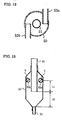
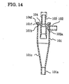
- FIG. 14 is an internal structural diagram of a conventional oil separator disclosed in Japanese Patent Laid-Open Publication No. Hei 8-319815.
- 101 represents a shell of a substantially cylindrical shape, wherein one of open ends 101a is of a small diameter, and the other open end 101b is of a large diameter.
- a taper section 101c is formed at the open end 101a, and a flange section 101f which extends out in radial direction is formed at the other open end 101b.
- an inlet pipe 102 is formed as an integral part of the shell 101, and an inlet port 102a is formed in the shell 101 in a tangential direction to the inner cylindrical surface of the shell 101.
- 103 represents an outlet pipe of a cylindrical shape with a collar section 104 formed around the middle section of the pipe, and this collar section 104 has a flange section 104f which is stuck onto the flange section 101f of the shell 101.
- a gas liquid mixture of gas and oil mist flows in from the inlet pipe 102 in a tangential direction to the inner surface of the shell 101 and circles around inside the shell 101, and centrifugal force causes the oil mist to separate and adhere to the inner surface of the shell 101, and then flow down along the inner surface and discharge from the open end 101a. Furthermore, the gas which remains after the oil mist has separated is discharged from the outlet pipe 103. Because an internal opening of the outlet pipe 103 inside the shell is larger than an external opening, the speed of the gas inside the shell 101 is reduced when being drawn into the outlet pipe 103, so that oil mist adhering to the outside wall of the outlet pipe 103 is prevented from being carried on the gas current and caught in the outlet pipe 103.
- FIG. 15 is a partial longitudinal sectional view of a conventional oil separator disclosed in Japanese Patent Laid-Open Publication No. Hei 9-177529.
- 201 represents a shell, which is provided with a cylindrical section 202a with an integrated flange section 202b extending outward at its top end. Furthermore, an inverted cone shaped cylinder 202c is integrally attached to the bottom edge of the cylindrical section 202a, and an oil recovery section 202d is integrally attached to the bottom opening of the inverted cone shaped cylinder 202c. In addition, an inlet pipe 203 is attached to an opening near the top end of the cylindrical section 202a. A circular lid 204 is fixed to the flange section 202b of the cylindrical section 202a. An outlet pipe 205 passes through the center of the lid 204. A non-woven fabric 206 of a predetermined shape is attached to the inside of the outlet pipe 205.
- gas incorporating oil mist flows from the inlet pipe 203 into the shell 201, and circles around within the cylindrical space formed between the cylindrical section 202a and the outlet pipe 205 extending into the cylindrical section 202a.
- the oil mist in the gas particularly with a particle diameter of 5 ⁇ m or greater, collides with the inner surface of the shell 201 and condenses, and when a particle grows to a sufficiently large diameter on the inner surface, gravity causes the particle to slide down the inner surface and flow into the oil recovery section 202d.
- the oil mist of a smaller particle diameter which has not separated out through collision with the inner surface of the shell 201, flows into the outlet pipe 205 together with the gas. Due to the effect of the circling motion inside the cylindrical space K, the gas does not pass straight through the outlet pipe 205, but rather moves upwards in a helical type circling motion. At this point, the velocity distribution of the gas stream is such that the velocity close to the pipe wall is large, whereas the velocity in the center is extremely small.
- the gas which is circling at high speed in a helical type motion around the periphery hits the non-woven fabric 206 attached to the pipe wall and is adsorbed.
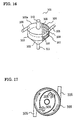
- FIG. 16 is a structural diagram showing a conventional gas liquid separator disclosed in Japanese Utility Model Laid-Open Publication No. Hei 6-60402, and FIG. 17 is a cross-sectional diagram viewed from above.
- a gas-liquid separator 301 includes a shell 304 formed of a combination of a cylinder 302 and a cone 303.
- Inlet pipes 305 for introducing a two phase flow in a tangential direction are provided on the side of the cylinder 302 of the shell 304, and this two phase flow is separated into a liquid and a vapor by the centrifugal force produced by the two phase flow circling around inside the shell 304, so that the liquid adheres to the inside wall of the shell 304 through self adhesion.
- a wick is also provided on the internal wall of the shell 304 for guiding the separated liquid into the cone 303.
- This wick is provided with a plurality of narrow grooves 306 of 0.3 to 0.5 mm formed in a helical pattern, and the force of the circling flow and the capillary phenomenon causes the liquid to move smoothly to the cone.
- a diaphragm 307 is provided inside the shell 304 to partition the shell into two portions on the sides of the cylinder 302 and the cone 303.
- the diaphragm 307 is provided with small apertures 308 for connecting the cylinder 302 side with the cone 303 side to maintain a uniform pressure within the shell 304.
- a gap 309 is provided between the outer perimeter of the diaphragm 307 and the inner surface of the shell 304.
- a wire gauze folded in a wave like pattern is put as a coarse wick, inside the cone 303 side of the shell 304 partitioned by the diaphragm 307, and functions as a liquid.
- a liquid guide pipe 311 for guiding liquid out of the shell 304 is formed at the apex of the cone 303. Furthermore, an outlet pipe 312 is formed in the center of the cylinder 302 side of the shell 304 partitioned by the diaphragm 307, so as to pass through the end plate 302a of the cylinder 302 side.
- the ideal positional relationship between the outlet pipe and the inlet pipes is unclear. Therefore, in systems in which the flow rate of the refrigerant varies in accordance with high pressure and low pressure fluctuations in the refrigerating cycle caused during load fluctuations, or in systems in which the compressor controls the capacity in accordance with the load, the system is unable to deal appropriately with such a problem that though the system operates appropriately at the time when the refrigerant flow rate is large, the velocity of the circling gas inside the oil separator falls and the oil separation efficiency resulting from the cyclone effect declines at the time when the refrigerant flow rate falls.
- the oil separation efficiency is the ratio of the volume of oil discharged from the discharge pipe per a unit of time, relative to the volume of oil flowing into the oil separator per the unit of time.
- the volume of oil accumulated inside the shell increases, and the accumulated oil inside the oil separator is lifted up by the gas flow inside the oil separator and flows out of the outlet pipe, producing a problem of a reduction in the oil separation efficiency.
- the present invention aims to solve the problems described above, and an object thereof is to provide an oil separator in which fluctuations in the pressure loss and the oil separation efficiency are small even in cases where the velocity of the gas flowing into the oil separator varies or the amount of oil accumulated inside the shell varies due to a variation in the flow rate of oil into the oil separator, and moreover in which the product cost is low.
- An oil separator is an oil separator comprising a shell having a cylindrical section and a taper section which narrows in a downward direction and which is formed as an integral part at the bottom of the aforementioned cylindrical section, an outlet pipe which is inserted through the top of the aforementioned shell so that the central axis of the outlet pipe coincides with the central axis of the shell, a discharge pipe connected to an opening provided at the bottom of the aforementioned taper section, and an inlet pipe connected tangentially to the inner surface of the aforementioned cylindrical section for introducing a gas liquid two phase flow into the aforementioned shell, characterized in that the distance between the aforementioned opening and the tip of the outlet pipe inside the shell is at least 5 times the inside diameter of the aforementioned inlet pipe.
- an oil separator is an oil separator comprising a shell having a cylindrical section and a taper section which narrows in a downward direction and which is formed as an integral part at the bottom of the aforementioned cylindrical section, an outlet pipe which is inserted through the top of the aforementioned shell so that the central axis of the outlet pipe coincides with the central axis of the shell, a discharge pipe connected to an opening provided at the bottom of the aforementioned taper section, and an inlet pipe connected tangentially to the inner surface of the aforementioned cylindrical section for introducing a gas liquid two phase flow into the aforementioned shell, characterized in that the tip of the outlet pipe inside the shell is positioned below the center of the inside diameter of the inlet pipe at a distance at least 5 times the inside diameter of the inlet pipe.
- an oil separator is an oil separator comprising a shell having a cylindrical section and a taper section which narrows in a downward direction and which is formed as an integral part at the bottom of the aforementioned cylindrical section, an outlet pipe which is inserted through the top of the aforementioned shell so that the central axis of the outlet pipe coincides with the central axis of the shell, a discharge pipe connected to an opening provided at the bottom of the aforementioned taper section, and an inlet pipe connected tangentially to the inner surface of the aforementioned cylindrical section for introducing a gas liquid two phase flow into the aforementioned shell, characterized in that the aforementioned inlet pipe has a straight pipe section connected to the aforementioned cylindrical section, and the length of this straight pipe section is at least 8 times the inside diameter of the inlet pipe.
- an oil separator is an oil separator comprising a shell having a cylindrical section and a taper section which narrows in a downward direction and which is formed as an integral part at the bottom of the aforementioned cylindrical section, an outlet pipe which is inserted through the top of the aforementioned shell so that the central axis of the outlet pipe coincides with the central axis of the shell, a discharge pipe connected to an opening provided at the bottom of the aforementioned taper section, and an inlet pipe connected tangentially to the inner surface of the aforementioned cylindrical section for introducing a gas liquid two phase flow into the aforementioned shell, characterized in that the aforementioned inlet pipe is a bent pipe having a first straight pipe section connected to the aforementioned cylindrical section and a second straight pipe section positioned at a 90 degree angle to the first straight pipe section in the direction of the aforementioned shell.
- an oil separator is an oil separator comprising a shell having a cylindrical section and a taper section which narrows in a downward direction and which is formed as an integral part at the bottom of the aforementioned cylindrical section, an outlet pipe which is inserted through the top of the aforementioned shell so that the central axis of the outlet pipe coincides with the central axis of the shell, a discharge pipe connected to an opening provided at the bottom of the aforementioned taper section, and an inlet pipe connected tangentially to the inner surface of the aforementioned cylindrical section for introducing a gas liquid two phase flow into the aforementioned shell, characterized in that the aforementioned inlet pipe is a spiral shape centered around the central axis of the aforementioned shell.
- the aforementioned shell has a taper section which narrows in a upward direction and which is formed on the top of the aforementioned cylinder section as an integral part of the cylindrical section.
- a plurality of inlet pipes are provided, and these inlet pipes are connected to the aforementioned cylindrical section at the same vertical height position with an equal spacing between the pipes.
- an outdoor apparatus is characterized by comprising a compressor, any one of the oil separators described above with an inlet pipe connected to the compressor, a capillary tube connected to a discharge pipe of the aforementioned oil separator, a valve connected to the discharge pipe in a parallel arrangement with the capillary tube, an oil return circuit connected to the capillary tube and the valve, an accumulator connected to the oil return circuit and the compressor, a four way valve connected to an outlet pipe of the aforementioned oil separator, and a heat exchanger connected to the four way valve.
- an outdoor apparatus is characterized by comprising a plurality of compressors, the aforementioned oil separator with each inlet pipe connected to one of the plurality of compressors, a capillary tube connected to the discharge pipe of the aforementioned oil separator, a valve connected to the discharge pipe in a parallel arrangement with the capillary tube, an oil return circuit connected to the capillary. tube and the valve, an accumulator connected to the oil return circuit and the aforementioned plurality of compressors, a four way valve connected to an outlet pipe of the aforementioned oil separator, and a heat exchanger connected to the four way valve.
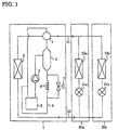
- FIG. 1 is a refrigerant circuit diagram of a refrigerating cycle with an oil separator according to an Embodiment 1 of the present invention.
- the refrigerating cycle comprises primarily a single outdoor apparatus 1, indoor apparatuses 20a, 20b, and a liquid pipe 30 and a gas pipe 31 connecting the outdoor apparatus 1 and the indoor apparatuses 20a, 20b.
- the outdoor apparatus 1 comprises primarily a compressor 2, an oil separator 3 connected to the compressor 2, a four way valve 4 connected to the oil separator 3, a heat source side heat exchanger 5 with one port connected to the four way valve 4 and the other port connected to the liquid pipe 30, an accumulator 6 connected to the compressor 2, an electromagnetic valve 7 connected to the oil separator 3, a capillary tube 8 connected to the oil separator 3 in a parallel arrangement with the electromagnetic valve 7, and an oil return circuit 9 connected to the electromagnetic valve 7, the capillary tube 8 and the accumulator.
- the four way valve 4 is also connected to the gas pipe 31.
- the indoor apparatus 20a comprises primarily a throttle device 21a connected to the liquid pipe 31, and a load side heat exchanger 22a with one port connected to the throttle device 21a and the other port connected to the gas pipe 30.
- the indoor apparatus 20b comprises primarily a throttle device 21b and a load side heat exchanger 22b.
- the electromagnetic valve 7 is closed. Oil carried out of the compressor 2 along with the refrigerant gas is separated out by the oil separator 3, reduced to a low pressure by the capillary tube 8, and is subsequently returned to the compressor 2 via the oil return circuit 9 and the accumulator 6.
- FIG. 2 is a top cross-sectional view of the oil separator 3
- FIG. 3 is a side cross-sectional view of the oil separator 3.
- 50 represents a shell of a cylindrical shape with both ends narrowed in tapered shape, and comprises a cylindrical section, a lower taper section beneath the cylindrical section, and an upper taper section above the cylindrical section.
- 51 represents a cylindrical outlet pipe, which is inserted into the inside of the shell 50 through the apex of the upper taper section of the shell 50, and this outlet pipe 51 is fixed so that the central axes of the outlet pipe 51 and the shell 50 coincide.
- 52 represents a discharge pipe, which is fixed to a lower opening 50a formed at the apex of the lower taper section of the shell 50.
- the tip 51a of the portion of the outlet pipe 51 inserted inside the shell 50 is positioned a distance L1 below the center of the tip of the inlet pipe 53 inside the shell 50, and a distance L2 above the lower opening 50a of the shell 50.
- a gas liquid two phase flow consisting of refrigerant gas and refrigerating machine oil discharged from the compressor 2 flows into the shell 50 from the inlet pipe 53.
- the gas liquid two phase flow which enters the shell 50 circles around and spirally sinks inside the shell 50.
- a cyclone effect is generated wherein the oil mist (fine particles of the refrigerating machine oil) is subjected to centrifugal forces and collides with, and adheres to, the inner surface of the shell 50, so that the oil mist suspended in the refrigerant gas is gradually separated out.
- the refrigerant gas flows out of the outlet pipe 51, and the refrigerating machine oil adhering to the inner surface of the shell 50 flows down the inner surface of the shell 50 under the effects of gravity, is discharged from the discharge pipe 52, flows through the oil return circuit 9 via the capillary tube 8, and is then returned to the compressor 2 via the accumulator 6.
- FIG. 4 is a diagram showing the relationship between L2 and the oil separation efficiency based on experimental results.
- the oil flow rate can be increased by reducing the flow passage resistance in the capillary tube 8 in the oil return circuit.
- the bypass volume of hot gas of the refrigerant will increase, and the performance of the refrigerating cycle will decline, so that using this method as means for increasing the oil separation efficiency is problematic.
- the distance L2 between the tip 51a of the outlet pipe 51 inside the shell 50 and the lower opening 50a of the shell 50 is at least 5D, then the liquid film at the bottom of the shell 50 is unlikely to be affected by the rotation of gas currents in a spiral motion within the shell 50, and as shown in FIG. 6, when the separated oil is discharged from the discharge pipe 52, gas from the central region is not dragged down with the oil, so that the oil is discharged as a single phase from the discharge pipe 52. As a result, pressure loss in the oil return circuit 9 can be suppressed, and the separated oil can be discharged smoothly.
- FIG. 7 is a diagram showing the relationship between L1 and the oil separation efficiency based on experimental results.
- the oil separation efficiency is dependent on the number of circulation made by the gas flow circling around inside the shell 50. Therefore, in order to increase the number of such circulation, the distance between the tip of the inlet pipe 53 inside the shell and the tip of the outlet pipe 51 should be maintained. This factor is reflected in FIG. 7, wherein by separating the positions of the lower tip of the outlet pipe 51 and the tip of the inlet pipe 53 inside the shell by a distance of at least 5D, the oil separation efficiency improves.
- the number of circulation of the gas flow inside the shell 50 necessary for oil separation can be ensured, even in the case where the refrigerant flow rate falls, so that the oil separation efficiency improves.
- FIG. 8 is a diagram showing the relationship between the length L3 of the straight pipe section from the tip of the inlet pipe 53 inside the shell 50 and the oil separation efficiency, based on experimental results.
- a construction as shown in Fig. 9 can be used, wherein the inlet pipe 53 is bent at approximately 90° in the horizontal plane so as to roughly match the circumferential direction of the shell 50, forming a first straight pipe section 54a and a second straight pipe section 54b.
- the inlet pipe 53 may be a spiral which is formed around the periphery of the shell 50 coaxially with the shell 50.
- the refrigerating machine oil also inclines to flow around the outer periphery of the inlet pipe 53, so that the oil separation efficiency improves.
- the number of components can be reduced, and the thickness required to achieve the necessary strength can also be reduced, in comparison with a case that the top is formed as a flat lid, so that the apparatus can be lightened.
- FIG. 11 is a refrigerant circuit diagram showing a refrigerating cycle according to an Embodiment 2 of the present invention, and represents the refrigerant cycle of FIG. 1 wherein two compressors are provided in the outdoor apparatus, and these two compressors are connected to an oil separator.
- FIG. 11 those components which are the same as, or correspond with components in FIG. 1 are labeled with the same symbols, and their description here is omitted.
- 2a and 2b represent compressors, and each of these compressors is connected to the oil separator 3, via a check valve 10a and a check valve 10b respectively.
- the electromagnetic valve 7 is opened to return the mixed liquid of refrigerant liquid and oil from the oil separator 3 to the inlet of the accumulator 6.
- any possibility of the oil separator 3 overflowing and oil being carried outside the outdoor apparatus system is prevented.
- the effect of preventing the overflow of the oil separator 3 is enhanced.
- the electromagnetic valve 7 is closed. Oil carried out of the compressor 2a and/or the compressor 2b along with the refrigerant gas is separated out in the oil separator 3, reduced to a low pressure by the capillary tube 8, sent into the oil return circuit 9, and subsequently returned to the compressor 2a and/or the compressor 2b via the accumulator 6.
- Capacity control of the compressor 2a and the compressor 2b is conducted in accordance with the load, by suitable starting and stopping of the compressors or by suitable adjustment of the operating frequency of the compressors.
- FIG. 12 is a top cross-sectional view of the oil separator 3
- FIG. 13 is a side cross-sectional view of the oil separator 3.
- 50 represents a shell of a cylindrical shape with both ends narrowed to taper sections.
- 51 represents a cylindrical outlet pipe, which passes through the apex of the upper taper section of the shell 50 and into the inside of the shell 50, and this outlet pipe 51 is fixed so that the central axes of the outlet pipe 51 and the shell 50 coincide.
- 52 represents a discharge pipe, which is fixed to a lower opening 50a formed at the apex of the lower taper section of the shell 50.
- 53a and 53b represent inlet pipes, which are cylindrical shaped pipes with a diameter D, positioned at the same vertical height on opposing sides relative to the central axis of the shell 50, and connected in a tangential direction to the inner surface of the shell 50.
- the tip 51a of the portion of the outlet pipe 51 inserted inside the shell 50 is positioned a distance L1 below the center of the tips of the inlet pipes 53a, 53b inside the shell 50, and a distance L2 above the lower opening 50a of the shell 50.
- the refrigerant gas flows out of the outlet pipe 51, and the refrigerating machine oil adhering to the inner surface of the shell 50 flows down the inner surface of the shell 50 under the effects of gravity and is discharged from the discharge pipe 52.
- the pressure loss of the oil separator 3 is dependent on the diameter of the inlet pipes. Therefore, if only one inlet pipe is used and the diameter of that pipe is excessively increased in order to reduce the pressure loss at the time when refrigerant is flowing from two operating compressors, the oil separation efficiency declines due to a reduction in the centrifugal separation effect at the time when only one compressor is operated and the flow rate drops. Consequently, by providing one inlet pipe for each compressor, pressure loss can be reduced, and any reduction in oil separation efficiency can be prevented at the time when only one compressor is operational. Furthermore, in a system with two compressors, the reliability of the refrigerating cycle can be improved at low cost by separating the oil carried out of the compressors with a single oil separator, and preventing depletion of the lubricant in the compressors.
- the trajectory of the refrigerant gas entering from one inlet pipe will not interfere with that from the other inlet pipe, so that gas flow turbulence within the shell 50 can be suppressed, and any reduction in oil separation efficiency during operation of the two compressors can be prevented.
- the distance between the shell opening and the tip of the outlet pipe inside the shell is at least 5 times the inside diameter of the inlet pipe. Therefore, even if the quantity of oil flowing into the oil separator increases, a reduction in the oil separation efficiency can be prevented.
- the tip of the outlet pipe inside the shell is positioned below the center of the inside diameter of the inlet pipe at a distance at least 5 times the inside diameter of the inlet pipe, so that the oil separation efficiency can be maintained at a high level across a wide range of refrigerant circulation flow volumes.
- the inlet pipe has a straight pipe section connected to the cylindrical section of the shell, and the length of this straight pipe section is at least 8 times the inside diameter of the inlet pipe, so that the oil separation efficiency can be increased at low cost even in the case where the gas flow rate is low.
- the inlet pipe is a bent pipe with a first straight pipe section connected to the cylindrical section and a second straight pipe section positioned at a 90 degree angle to the first straight pipe section in the direction of the aforementioned shell, or alternatively, in an oil separator according to the present invention, the inlet pipe is a spiral formed around the central axis of the shell, so that the separation efficiency can be improved even in the case where the installation space is limited.
- the shell comprises a taper section narrowing in a upward direction, which is formed on the top of the aforementioned cylindrical section as an integral part of the cylindrical section. So, in comparison with a case where the top is formed as a flat lid, the number of components can be reduced, and the thickness required to achieve the necessary strength can also be reduced, so that the apparatus can be lightened.
- a plurality of inlet pipes are provided, and these inlet pipes are connected to the cylindrical section at the same vertical position with an equal spacing between pipes. Consequently, pressure loss can be reduced, and any reduction in oil separation efficiency can be prevented when only one compressor is operated. Furthermore, in a system with two compressors, the reliability of the refrigerating cycle can be improved at low cost by separating the oil carried out of the compressors with a single oil separator, and preventing depletion of the lubricant in the compressors. Moreover, the trajectory of the refrigerant gas entering from one inlet pipe will not interfere with that from the other inlet pipe, so that gas flow turbulence within the shell can be suppressed, and any reduction in oil separation efficiency during operation of the two compressors can be prevented.
- an outdoor apparatus comprises a compressor, an oil separator as described above with an inlet pipe connected to the compressor, a capillary tube connected to the discharge pipe of this oil separator, a valve connected to the discharge pipe in a parallel arrangement with the capillary tube, an oil return circuit connected to the capillary tube and the valve, an accumulator connected to the oil return circuit and the compressor, a four way valve connected to the outlet pipe of the oil separator, and a heat exchanger connected to the four way valve, so that the operating efficiency of the apparatus improves.
- an outdoor apparatus comprises a plurality of compressors, the aforementioned oil separator with each inlet pipe connected to one of the plurality of compressors, a capillary tube connected to the discharge pipe of the oil separator, a valve connected to the discharge pipe in a parallel arrangement with the capillary tube, an oil return circuit connected to the capillary tube and the valve, an accumulator connected to the oil return circuit and the plurality of compressors, a four way valve connected to the outlet pipe of the aforementioned oil separator, and a heat exchanger connected to the four way valve, so that the operating efficiency of the apparatus improves.
- valve is opened only during startup of a compressor, so that any overflow of the oil separator can be prevented, even during startup of a compressor when the oil flow rate into the oil separator increases temporarily.
Landscapes
- Engineering & Computer Science (AREA)
- Physics & Mathematics (AREA)
- Mechanical Engineering (AREA)
- Thermal Sciences (AREA)
- General Engineering & Computer Science (AREA)
- Chemical & Material Sciences (AREA)
- Analytical Chemistry (AREA)
- Power Engineering (AREA)
- Chemical Kinetics & Catalysis (AREA)
- Applications Or Details Of Rotary Compressors (AREA)
- Compressor (AREA)
Abstract
Description
Claims (10)
- An oil separator comprising a shell having a cylindrical section and a taper section which narrows in a downward direction and which is formed as an integral part at a bottom of said cylindrical section, an outlet pipe which is inserted through a top of said shell so that a central axis of said outlet pipe coincides with a central axis of said shell, a discharge pipe connected to an opening provided at a bottom of said taper section, and an inlet pipe connected tangentially to an inner surface of said cylindrical section for introducing a gas liquid two phase flow into said shell, characterized in that a distance between said opening and a tip of said outlet pipe inside said shell is at least 5 times an inside diameter of said inlet pipe.
- An oil separator comprising a shell having a cylindrical section and a taper section which narrows in a downward direction and which is formed as an integral part at a bottom of said cylindrical section, an outlet pipe which is inserted through a top of said shell so that a central axis of said outlet pipe coincides with a central axis of said shell, a discharge pipe connected to an opening provided at a bottom of said taper section, and an inlet pipe connected tangentially to an inner surface of said cylindrical section for introducing a gas liquid two phase flow into said shell, characterized in that a tip of said outlet pipe inside said shell is positioned below a center of an inside diameter of said inlet pipe at a distance at least 5 times said inside diameter of said inlet pipe.
- An oil separator comprising a shell having a cylindrical section and a taper section which narrows in a downward direction and which is formed as an integral part at a bottom of said cylindrical section, an outlet pipe which is inserted through a top of said shell so that a central axis of said outlet pipe coincides with a central axis of said shell, a discharge pipe connected to an opening provided at a bottom of said taper section, and an inlet pipe connected tangentially to an inner surface of said cylindrical section for introducing a gas liquid two phase flow into said shell, characterized in that said inlet pipe has a straight pipe section connected to said cylindrical section, and a length of said straight pipe section is at least 8 times an inside diameter of said inlet pipe.
- An oil separator comprising a shell having a cylindrical section and a taper section which narrows in a downward direction and which is formed as an integral part at a bottom of said cylindrical section, an outlet pipe which is inserted through a top of said shell so that a central axis of said outlet pipe coincides with a central axis of said shell, a discharge pipe connected to an opening provided at a bottom of said taper section, and an inlet pipe connected tangentially to an inner surface of said cylindrical section for introducing a gas liquid two phase flow into said shell, characterized in that said inlet pipe is a bent pipe having a first straight pipe section connected to said cylindrical section and a second straight pipe section bent at a 90 degree angle to said first straight pipe section in a direction of said shell.
- An oil separator comprising a shell having 'a cylindrical section and a taper-section which narrows in a downward direction and which is formed as an integral part at a bottom of said cylindrical section, an outlet pipe which is inserted through a top of said shell so that a central axis of said outlet pipe coincides with a central axis of said shell, a discharge pipe connected to an opening provided at a bottom of said taper section, and an inlet pipe connected tangentially to an inner surface of said cylindrical section for introducing a gas liquid two phase flow into said shell, characterized in that said inlet pipe is a spiral shape centered around a central axis of said shell.
- The oil separator according to any one of claim 1 through claim 5, wherein said shell comprises a taper section which narrows in an upward direction and which is formed on top of said cylinder section as an integral part of said cylindrical section.
- The oil separator according to any one of claim 1 through claim 6, wherein, a plurality of said inlet pipes are provided, and said inlet pipes are connected to said cylindrical section at an identical vertical height position and with an equal spacing between said inlet pipes.
- An outdoor apparatus characterized by comprising a compressor, the oil separator according to any one of claim 1 through claim 6 with an inlet pipe connected to said compressor, a capillary tube connected to a discharge pipe of said oil separator, a valve connected to said discharge pipe in a parallel arrangement with said capillary tube, an oil return circuit connected to said capillary tube and said valve, an accumulator connected to said oil return circuit and said compressor, a four way valve connected to an outlet pipe of said oil separator, and a heat exchanger connected to said four way valve.
- An outdoor apparatus characterized by comprising a plurality of compressors, the oil separator according to claim 7 with each inlet pipe connected to one of said plurality of compressors, a capillary tube connected to the discharge pipe of said oil separator, a valve connected to said discharge pipe in a parallel arrangement with said capillary tube, an oil return circuit connected to said capillary tube and said valve, an accumulator connected to said oil return circuit and said plurality of compressors, a four way valve connected to an outlet pipe of said oil separator, and a heat exchanger connected to said four way valve.
- An outdoor apparatus according to any one of claim 8 and claim 9, characterized in that said valve is opened only during startup of said compressor.
Applications Claiming Priority (3)
| Application Number | Priority Date | Filing Date | Title |
|---|---|---|---|
| JP2000249903 | 2000-08-21 | ||
| JP2000249903A JP4356214B2 (en) | 2000-08-21 | 2000-08-21 | Oil separator and outdoor unit |
| PCT/JP2001/006771 WO2002016840A1 (en) | 2000-08-21 | 2001-08-07 | Oil separator and outdoor unit with the oil separator |
Publications (3)
| Publication Number | Publication Date |
|---|---|
| EP1312879A1 true EP1312879A1 (en) | 2003-05-21 |
| EP1312879A4 EP1312879A4 (en) | 2004-08-11 |
| EP1312879B1 EP1312879B1 (en) | 2008-06-11 |
Family
ID=18739575
Family Applications (1)
| Application Number | Title | Priority Date | Filing Date |
|---|---|---|---|
| EP01954482A Expired - Lifetime EP1312879B1 (en) | 2000-08-21 | 2001-08-07 | Oil separator and outdoor unit with the oil separator |
Country Status (8)
| Country | Link |
|---|---|
| US (1) | US6574986B2 (en) |
| EP (1) | EP1312879B1 (en) |
| JP (1) | JP4356214B2 (en) |
| KR (1) | KR100516577B1 (en) |
| CN (1) | CN1232790C (en) |
| DE (1) | DE60134413D1 (en) |
| ES (1) | ES2307635T3 (en) |
| WO (1) | WO2002016840A1 (en) |
Cited By (7)
| Publication number | Priority date | Publication date | Assignee | Title |
|---|---|---|---|---|
| DE102005061256A1 (en) * | 2005-12-20 | 2007-06-21 | Günter Dr. Slowik | Method and device for deoiling crankcase ventilation gases of an internal combustion engine |
| EP1392413B1 (en) * | 2001-06-01 | 2007-11-07 | Celanese International Corporation | Methods for reducing entrainment of solids and liquids |
| DE102006038700A1 (en) * | 2006-08-18 | 2008-02-21 | Polytec Automotive Gmbh & Co. Kg | Device for separating liquids from gases |
| DE102007022922A1 (en) * | 2007-05-14 | 2009-04-02 | Rolls-Royce Deutschland Ltd & Co Kg | Oil separator for airplane gas turbine, has vent line supplying oil air mixture to separator, where line is provided with angle region with respect to axle center and region is not essentially provided with transition roundings |
| EP3341663A4 (en) * | 2015-12-25 | 2018-07-11 | Samsung Electronics Co., Ltd. | Oil separator |
| EP3254037A4 (en) * | 2015-02-06 | 2018-10-24 | Trane International Inc. | Lubricant separator |
| US10655899B2 (en) | 2015-12-25 | 2020-05-19 | Samsung Electronics Co., Ltd. | Oil separator |
Families Citing this family (53)
| Publication number | Priority date | Publication date | Assignee | Title |
|---|---|---|---|---|
| US20040197622A1 (en) * | 2003-04-04 | 2004-10-07 | Texaco Inc. | Method and apparatus for separating liquid from a gas stream |
| CN1878991A (en) * | 2003-10-08 | 2006-12-13 | 谷轮公司 | Distributed condensing units |
| KR100613505B1 (en) * | 2004-02-25 | 2006-08-17 | 엘지전자 주식회사 | Refrigeration cycle unit |
| KR100619785B1 (en) * | 2005-05-16 | 2006-09-06 | 엘지전자 주식회사 | Oil separator |
| US20060280622A1 (en) * | 2005-06-10 | 2006-12-14 | Samsung Electronics Co., Ltd. | Oil separator for air conditioner |
| KR100745419B1 (en) * | 2005-06-10 | 2007-08-02 | 삼성전자주식회사 | Oil separator of air conditioner |
| RU2302296C1 (en) * | 2005-11-24 | 2007-07-10 | Государственное образовательное учреждение высшего профессионального образования "Тюменский государственный нефтегазовый университет" | Vortex chamber |
| DE102006038726B4 (en) * | 2006-08-11 | 2011-06-09 | Visteon Global Technologies Inc., Van Buren | Refrigerant compressor for air conditioning and method for oil separation and pressure pulsation damping this |
| DE102006041213B4 (en) * | 2006-09-02 | 2017-06-29 | Mahle International Gmbh | Device for crank chamber ventilation |
| JP4903119B2 (en) * | 2007-06-25 | 2012-03-28 | 三菱電機株式会社 | Gas-liquid separator and air conditioner equipped with it |
| US8429930B2 (en) * | 2007-07-12 | 2013-04-30 | Johnson Controls Technology Company | Oil separator |
| US7708793B2 (en) * | 2007-08-29 | 2010-05-04 | Bendix Commercial Vehicle Systems Llc | Purge exhaust processor |
| JP5366671B2 (en) * | 2009-06-12 | 2013-12-11 | 三菱電機株式会社 | Cyclone oil separator, compression refrigeration apparatus and air compression apparatus provided with the same |
| JP2011202876A (en) * | 2010-03-25 | 2011-10-13 | Hitachi Appliances Inc | Centrifugal oil separator and outdoor unit of air conditioning device |
| NO2734797T3 (en) | 2011-07-19 | 2018-01-27 | ||
| KR101342649B1 (en) * | 2011-10-21 | 2013-12-17 | 엘지전자 주식회사 | Air conditioner |
| KR101340532B1 (en) | 2011-10-21 | 2013-12-11 | 엘지전자 주식회사 | Oil separator and air conditioner comprising the same |
| US20130255308A1 (en) * | 2012-03-29 | 2013-10-03 | Johnson Controls Technology Company | Chiller or heat pump with a falling film evaporator and horizontal oil separator |
| WO2014054090A1 (en) * | 2012-10-01 | 2014-04-10 | 三菱電機株式会社 | Air conditioning device |
| JP6219032B2 (en) | 2012-12-10 | 2017-10-25 | 三菱重工サーマルシステムズ株式会社 | Oil separator |
| JP5921425B2 (en) * | 2012-12-12 | 2016-05-24 | ヤンマー株式会社 | air conditioner |
| CN102997523B (en) * | 2012-12-14 | 2015-03-25 | 江苏苏净集团有限公司 | Gas-liquid separator adopted by carbon dioxide heat pump system |
| EP3006864B1 (en) * | 2013-06-06 | 2020-10-28 | Panasonic Intellectual Property Management Co., Ltd. | Oil separator and method for manufacturing oil separator |
| JP5657061B2 (en) * | 2013-06-19 | 2015-01-21 | 三菱電機株式会社 | Cyclone oil separator, compression refrigeration apparatus and air compression apparatus provided with the same |
| GB201321629D0 (en) * | 2013-12-06 | 2014-01-22 | J & E Hall Ltd | External separator |
| CN103673436B (en) * | 2013-12-24 | 2016-01-06 | 上海交通大学 | A gas-liquid separator with functions of oil return and liquid discharge |
| JPWO2015107610A1 (en) * | 2014-01-14 | 2017-03-23 | 株式会社日立産機システム | Gas-liquid separator and air compressor provided with the same |
| JP5858187B2 (en) * | 2014-05-13 | 2016-02-10 | ダイキン工業株式会社 | Oil separator |
| CN105091432B (en) * | 2014-05-14 | 2018-01-02 | Lg电子株式会社 | Oil eliminator and the air-conditioning with the oil eliminator |
| WO2015173939A1 (en) * | 2014-05-15 | 2015-11-19 | 三菱電機株式会社 | Refrigeration unit |
| JP2016065677A (en) * | 2014-09-25 | 2016-04-28 | アイシン精機株式会社 | Oil separator for refrigerant |
| JP6432339B2 (en) * | 2014-12-25 | 2018-12-05 | 株式会社デンソー | Refrigeration cycle equipment |
| WO2016139838A1 (en) * | 2015-03-05 | 2016-09-09 | ブラザー工業株式会社 | Gas-liquid separator for fuel cell system |
| CN104896815B (en) * | 2015-06-03 | 2018-01-16 | 中国科学院广州能源研究所 | A kind of double centrifugation flash vessels |
| DE102015121583B4 (en) * | 2015-12-11 | 2021-02-11 | Hanon Systems | Device for separating oil from a refrigerant-oil mixture and for cooling the oil and for cooling and / or liquefying the refrigerant in a refrigerant circuit |
| CN106196776A (en) * | 2016-08-19 | 2016-12-07 | 重庆美的通用制冷设备有限公司 | Gas-liquid separator and there is its source pump |
| JP6847216B2 (en) * | 2017-06-23 | 2021-03-24 | 三菱電機株式会社 | Refrigeration cycle equipment |
| CN107218747A (en) * | 2017-07-27 | 2017-09-29 | 安徽美芝精密制造有限公司 | Reservoir and the compressor with it |
| CN107461965B (en) * | 2017-08-24 | 2023-03-10 | 广东美芝制冷设备有限公司 | Liquid receiver of compressor, compressor and refrigeration system |
| JP6827554B2 (en) * | 2017-09-28 | 2021-02-10 | 三菱電機株式会社 | Oil separator and air conditioner equipped with it |
| US11713760B2 (en) * | 2017-12-28 | 2023-08-01 | Emerson Climate Technologies (Suzhou) Co., Ltd. | Intake pipe used for compressor system and compressor system |
| DE102019111017A1 (en) * | 2019-04-29 | 2020-10-29 | Wolf Gmbh | Refrigerant separator for a heat pump system |
| JP7267088B2 (en) * | 2019-05-10 | 2023-05-01 | 東京エレクトロン株式会社 | Tanks, substrate processing equipment, and methods of using tanks |
| WO2021081377A1 (en) | 2019-10-24 | 2021-04-29 | Johnson Controls Technology Company | Centrifugal flash tank |
| WO2021084740A1 (en) * | 2019-11-01 | 2021-05-06 | 太平洋工業株式会社 | Integrated valve |
| CN114867974B (en) * | 2019-12-27 | 2024-03-29 | 三菱电机株式会社 | Gas-liquid separation device and refrigeration cycle device |
| US11353250B2 (en) * | 2020-01-10 | 2022-06-07 | Heatcraft Refrigeration Products Llc | Vertical oil separator |
| CN111595067A (en) * | 2020-05-08 | 2020-08-28 | 珠海格力电器股份有限公司 | Multi-cylinder compressor oil return system, air conditioning system and control method |
| JP2021196152A (en) * | 2020-06-18 | 2021-12-27 | ホシザキ株式会社 | Cooling storage |
| KR200499808Y1 (en) * | 2020-08-28 | 2025-12-01 | 한일튜브 주식회사 | Phase separator and cooling system with the same |
| CN114608226B (en) * | 2020-12-08 | 2024-07-23 | 合肥美的暖通设备有限公司 | Oil separator and air conditioner outdoor unit |
| CN112648754B (en) * | 2020-12-14 | 2023-07-14 | 青岛海信日立空调系统有限公司 | An air conditioning circulation system and circulation method thereof |
| CN114542431A (en) * | 2022-02-14 | 2022-05-27 | 福州市虚谷技术有限公司 | Novel vertical oil separator structure for compressor |
Family Cites Families (20)
| Publication number | Priority date | Publication date | Assignee | Title |
|---|---|---|---|---|
| US2704603A (en) * | 1955-03-22 | meaders | ||
| GB759118A (en) * | 1953-10-23 | 1956-10-10 | Ca Nat Research Council | Centrifugal separator |
| US3288300A (en) * | 1962-02-14 | 1966-11-29 | Bauer Bros Co | Centrifugal cleaner |
| JPS472949B1 (en) * | 1969-07-31 | 1972-01-26 | ||
| US3953184A (en) * | 1974-09-18 | 1976-04-27 | Stockford William F | Cyclone-type dust separator |
| FI58954C (en) * | 1979-08-20 | 1981-05-11 | Enso Gutzeit Oy | HYDROCYKLON |
| FR2485952A1 (en) * | 1980-07-07 | 1982-01-08 | Ishikawajima Harima Heavy Ind | Cyclone for separating particles from gas - used as preheater in calcining cement and alumina |
| AT382910B (en) * | 1982-12-09 | 1987-04-27 | Escher Wyss Gmbh | HISTORIC SIFTER FOR SEPARATING IMPURITIES FROM FABRIC SUSPENSIONS |
| US4710299A (en) * | 1984-01-24 | 1987-12-01 | Noel Carroll | Cyclone separator |
| JPH0372276U (en) * | 1989-11-10 | 1991-07-22 | ||
| JPH05329401A (en) | 1992-05-28 | 1993-12-14 | Daikin Ind Ltd | Centrifuge type oil separator and its manufacture |
| US5369958A (en) * | 1992-10-15 | 1994-12-06 | Mitsubishi Denki Kabushiki Kaisha | Air conditioner |
| JP2599831Y2 (en) * | 1993-01-27 | 1999-09-20 | 石川島播磨重工業株式会社 | Gas-liquid separator for space |
| JP3124908B2 (en) | 1995-05-26 | 2001-01-15 | 小島プレス工業株式会社 | Oil trapper for internal combustion engine |
| JPH09177529A (en) | 1995-12-25 | 1997-07-08 | Tokai Rubber Ind Ltd | Oil mist separation and collection device |
| DE19612059A1 (en) * | 1996-03-27 | 1997-10-02 | Fraunhofer Ges Forschung | Cyclone separator for cleaning dirty liquids |
| TW336270B (en) * | 1997-01-17 | 1998-07-11 | Sanyo Electric Ltd | Compressor and air conditioner |
| JPH1163690A (en) | 1997-08-13 | 1999-03-05 | Mitsubishi Heavy Ind Ltd | Refrigerating apparatus |
| US5970772A (en) * | 1999-03-01 | 1999-10-26 | Kotobuki Sangyo Kabushiki Kaisha | Positioning control device for guide apparatus |
| WO2001017638A2 (en) * | 1999-09-09 | 2001-03-15 | Kadant Black Clawson, Inc. | Constant arc contour hydrocyclone cleaner |
-
2000
- 2000-08-21 JP JP2000249903A patent/JP4356214B2/en not_active Expired - Lifetime
-
2001
- 2001-08-07 US US10/088,519 patent/US6574986B2/en not_active Expired - Lifetime
- 2001-08-07 CN CNB018024750A patent/CN1232790C/en not_active Expired - Lifetime
- 2001-08-07 ES ES01954482T patent/ES2307635T3/en not_active Expired - Lifetime
- 2001-08-07 WO PCT/JP2001/006771 patent/WO2002016840A1/en not_active Ceased
- 2001-08-07 EP EP01954482A patent/EP1312879B1/en not_active Expired - Lifetime
- 2001-08-07 DE DE60134413T patent/DE60134413D1/en not_active Expired - Lifetime
- 2001-08-07 KR KR10-2002-7004337A patent/KR100516577B1/en not_active Expired - Lifetime
Cited By (9)
| Publication number | Priority date | Publication date | Assignee | Title |
|---|---|---|---|---|
| EP1392413B1 (en) * | 2001-06-01 | 2007-11-07 | Celanese International Corporation | Methods for reducing entrainment of solids and liquids |
| DE102005061256A1 (en) * | 2005-12-20 | 2007-06-21 | Günter Dr. Slowik | Method and device for deoiling crankcase ventilation gases of an internal combustion engine |
| DE102006038700A1 (en) * | 2006-08-18 | 2008-02-21 | Polytec Automotive Gmbh & Co. Kg | Device for separating liquids from gases |
| US8267071B2 (en) | 2006-08-18 | 2012-09-18 | Polytec Automotive Gmbh & Co. Kg | Device for separating liquids from gases |
| DE102006038700B4 (en) | 2006-08-18 | 2021-11-11 | Polytec Plastics Germany Gmbh & Co. Kg | Device for separating liquids from gases |
| DE102007022922A1 (en) * | 2007-05-14 | 2009-04-02 | Rolls-Royce Deutschland Ltd & Co Kg | Oil separator for airplane gas turbine, has vent line supplying oil air mixture to separator, where line is provided with angle region with respect to axle center and region is not essentially provided with transition roundings |
| EP3254037A4 (en) * | 2015-02-06 | 2018-10-24 | Trane International Inc. | Lubricant separator |
| EP3341663A4 (en) * | 2015-12-25 | 2018-07-11 | Samsung Electronics Co., Ltd. | Oil separator |
| US10655899B2 (en) | 2015-12-25 | 2020-05-19 | Samsung Electronics Co., Ltd. | Oil separator |
Also Published As
| Publication number | Publication date |
|---|---|
| KR20020070965A (en) | 2002-09-11 |
| CN1232790C (en) | 2005-12-21 |
| WO2002016840A1 (en) | 2002-02-28 |
| DE60134413D1 (en) | 2008-07-24 |
| CN1388888A (en) | 2003-01-01 |
| KR100516577B1 (en) | 2005-09-22 |
| JP4356214B2 (en) | 2009-11-04 |
| EP1312879B1 (en) | 2008-06-11 |
| EP1312879A4 (en) | 2004-08-11 |
| US20020134102A1 (en) | 2002-09-26 |
| US6574986B2 (en) | 2003-06-10 |
| JP2002061993A (en) | 2002-02-28 |
| ES2307635T3 (en) | 2008-12-01 |
Similar Documents
| Publication | Publication Date | Title |
|---|---|---|
| US6574986B2 (en) | Oil separator and outdoor unit with the oil separator | |
| JP2830618B2 (en) | Centrifugal oil separator | |
| CN1325169C (en) | Improved Separator | |
| US10688426B2 (en) | Methods and apparatuses for separating liquid particles from a gas-liquid stream | |
| CA2513208C (en) | A water separator for air-conditioning systems | |
| CN107062716B (en) | Vertical oil separator and air conditioning system | |
| CN101229462A (en) | droplet separator | |
| JP2017503989A (en) | External separator | |
| CN118201689A (en) | Separator device, compressor having a separator device, and refrigeration system having a separator device | |
| EP1681522B1 (en) | Gas liquid separator | |
| CN108619795A (en) | Gas-liquid separation device, the refrigerating plant for having gas-liquid separation device and the fluid mechanical device for having gas-liquid separation device | |
| WO2022121432A1 (en) | Oil separator and outdoor unit of air conditioner | |
| JPH05312438A (en) | Centrifugal oil separator | |
| US20080264009A1 (en) | Cyclone Collector | |
| CN111256399B (en) | Oil separator and refrigeration system with same | |
| JP2010048483A (en) | Gas-liquid separator and air compression device and air conditioner equipped with the gas-liquid separator | |
| JPH11248296A (en) | Oil separator | |
| JP4069567B2 (en) | accumulator | |
| JP7130838B2 (en) | Gas-liquid separator and refrigeration cycle equipment | |
| CN211625773U (en) | Falling-film evaporators and chillers with cyclones | |
| JP2000070632A (en) | Rotating gas-liquid separator | |
| EP4083541A1 (en) | Gas-liquid separation device and refrigeration cycle device | |
| JP2001099526A (en) | Oil separator | |
| JP2006266524A (en) | accumulator | |
| JP2008045763A (en) | Oil separator |
Legal Events
| Date | Code | Title | Description |
|---|---|---|---|
| PUAI | Public reference made under article 153(3) epc to a published international application that has entered the european phase |
Free format text: ORIGINAL CODE: 0009012 |
|
| 17P | Request for examination filed |
Effective date: 20020418 |
|
| AK | Designated contracting states |
Designated state(s): AT BE CH CY DE DK ES FI FR GB GR IE IT LI LU MC NL PT SE TR |
|
| RBV | Designated contracting states (corrected) |
Designated state(s): AT BE CH CY DE ES FR GB IT LI |
|
| A4 | Supplementary search report drawn up and despatched |
Effective date: 20040629 |
|
| RIC1 | Information provided on ipc code assigned before grant |
Ipc: 7F 25B 43/02 A Ipc: 7B 04C 5/081 B |
|
| 17Q | First examination report despatched |
Effective date: 20050223 |
|
| RAP1 | Party data changed (applicant data changed or rights of an application transferred) |
Owner name: MITSUBISHI DENKI KABUSHIKI KAISHA |
|
| 17Q | First examination report despatched |
Effective date: 20050223 |
|
| GRAP | Despatch of communication of intention to grant a patent |
Free format text: ORIGINAL CODE: EPIDOSNIGR1 |
|
| GRAS | Grant fee paid |
Free format text: ORIGINAL CODE: EPIDOSNIGR3 |
|
| RIN1 | Information on inventor provided before grant (corrected) |
Inventor name: MURAKAMI, HIROKI Inventor name: KOGE, HIROFUMI Inventor name: KASAI, TOMOHIKO Inventor name: MORIMOTO, OSAMU |
|
| GRAA | (expected) grant |
Free format text: ORIGINAL CODE: 0009210 |
|
| AK | Designated contracting states |
Kind code of ref document: B1 Designated state(s): DE ES FR GB IT |
|
| RBV | Designated contracting states (corrected) |
Designated state(s): DE ES FR GB IT |
|
| REG | Reference to a national code |
Ref country code: GB Ref legal event code: FG4D |
|
| RIN2 | Information on inventor provided after grant (corrected) |
Inventor name: KOGE, HIROFUMI Inventor name: MORIMOTO, OSAMU Inventor name: MURAKAMI, HIROKI Inventor name: KASAI, TOMOHIKO |
|
| REF | Corresponds to: |
Ref document number: 60134413 Country of ref document: DE Date of ref document: 20080724 Kind code of ref document: P |
|
| REG | Reference to a national code |
Ref country code: ES Ref legal event code: FG2A Ref document number: 2307635 Country of ref document: ES Kind code of ref document: T3 |
|
| PLBE | No opposition filed within time limit |
Free format text: ORIGINAL CODE: 0009261 |
|
| STAA | Information on the status of an ep patent application or granted ep patent |
Free format text: STATUS: NO OPPOSITION FILED WITHIN TIME LIMIT |
|
| 26N | No opposition filed |
Effective date: 20090312 |
|
| REG | Reference to a national code |
Ref country code: GB Ref legal event code: 746 Effective date: 20110513 |
|
| REG | Reference to a national code |
Ref country code: DE Ref legal event code: R084 Ref document number: 60134413 Country of ref document: DE Effective date: 20110704 Ref country code: DE Ref legal event code: R084 Ref document number: 60134413 Country of ref document: DE Effective date: 20110506 |
|
| REG | Reference to a national code |
Ref country code: ES Ref legal event code: GC2A Effective date: 20111027 |
|
| REG | Reference to a national code |
Ref country code: FR Ref legal event code: PLFP Year of fee payment: 16 |
|
| REG | Reference to a national code |
Ref country code: FR Ref legal event code: PLFP Year of fee payment: 17 |
|
| REG | Reference to a national code |
Ref country code: FR Ref legal event code: PLFP Year of fee payment: 18 |
|
| PGFP | Annual fee paid to national office [announced via postgrant information from national office to epo] |
Ref country code: GB Payment date: 20200729 Year of fee payment: 20 Ref country code: FR Payment date: 20200715 Year of fee payment: 20 Ref country code: ES Payment date: 20200901 Year of fee payment: 20 Ref country code: DE Payment date: 20200729 Year of fee payment: 20 |
|
| PGFP | Annual fee paid to national office [announced via postgrant information from national office to epo] |
Ref country code: IT Payment date: 20200713 Year of fee payment: 20 |
|
| REG | Reference to a national code |
Ref country code: DE Ref legal event code: R071 Ref document number: 60134413 Country of ref document: DE |
|
| REG | Reference to a national code |
Ref country code: GB Ref legal event code: PE20 Expiry date: 20210806 |
|
| PG25 | Lapsed in a contracting state [announced via postgrant information from national office to epo] |
Ref country code: GB Free format text: LAPSE BECAUSE OF EXPIRATION OF PROTECTION Effective date: 20210806 |
|
| REG | Reference to a national code |
Ref country code: ES Ref legal event code: FD2A Effective date: 20211203 |
|
| PG25 | Lapsed in a contracting state [announced via postgrant information from national office to epo] |
Ref country code: ES Free format text: LAPSE BECAUSE OF EXPIRATION OF PROTECTION Effective date: 20210808 |