EP1312861A2 - Abluftreinigungsvorrichtung - Google Patents
Abluftreinigungsvorrichtung Download PDFInfo
- Publication number
- EP1312861A2 EP1312861A2 EP02025540A EP02025540A EP1312861A2 EP 1312861 A2 EP1312861 A2 EP 1312861A2 EP 02025540 A EP02025540 A EP 02025540A EP 02025540 A EP02025540 A EP 02025540A EP 1312861 A2 EP1312861 A2 EP 1312861A2
- Authority
- EP
- European Patent Office
- Prior art keywords
- container
- heat storage
- storage mass
- access opening
- outlet opening
- Prior art date
- Legal status (The legal status is an assumption and is not a legal conclusion. Google has not performed a legal analysis and makes no representation as to the accuracy of the status listed.)
- Granted
Links
- 238000005338 heat storage Methods 0.000 claims abstract description 113
- 238000002485 combustion reaction Methods 0.000 claims abstract description 20
- 230000003197 catalytic effect Effects 0.000 claims abstract description 4
- 238000000746 purification Methods 0.000 claims abstract description 3
- 239000007789 gas Substances 0.000 claims description 73
- 238000010438 heat treatment Methods 0.000 claims description 3
- 239000000470 constituent Substances 0.000 claims description 2
- 238000007599 discharging Methods 0.000 claims description 2
- 230000005484 gravity Effects 0.000 claims 1
- 238000004887 air purification Methods 0.000 description 27
- 239000003344 environmental pollutant Substances 0.000 description 5
- 231100000719 pollutant Toxicity 0.000 description 5
- 238000010926 purge Methods 0.000 description 5
- 230000003068 static effect Effects 0.000 description 4
- 230000002349 favourable effect Effects 0.000 description 3
- 238000000265 homogenisation Methods 0.000 description 3
- 230000003647 oxidation Effects 0.000 description 3
- 238000007254 oxidation reaction Methods 0.000 description 3
- 238000005094 computer simulation Methods 0.000 description 2
- 239000000446 fuel Substances 0.000 description 2
- 239000011149 active material Substances 0.000 description 1
- 239000003054 catalyst Substances 0.000 description 1
- 229910010293 ceramic material Inorganic materials 0.000 description 1
- 239000011248 coating agent Substances 0.000 description 1
- 238000000576 coating method Methods 0.000 description 1
- 238000011010 flushing procedure Methods 0.000 description 1
- 238000009413 insulation Methods 0.000 description 1
- 239000000463 material Substances 0.000 description 1
- 239000003973 paint Substances 0.000 description 1
Images




Classifications
-
- F—MECHANICAL ENGINEERING; LIGHTING; HEATING; WEAPONS; BLASTING
- F23—COMBUSTION APPARATUS; COMBUSTION PROCESSES
- F23G—CREMATION FURNACES; CONSUMING WASTE PRODUCTS BY COMBUSTION
- F23G7/00—Incinerators or other apparatus for consuming industrial waste, e.g. chemicals
- F23G7/06—Incinerators or other apparatus for consuming industrial waste, e.g. chemicals of waste gases or noxious gases, e.g. exhaust gases
- F23G7/07—Incinerators or other apparatus for consuming industrial waste, e.g. chemicals of waste gases or noxious gases, e.g. exhaust gases in which combustion takes place in the presence of catalytic material
-
- B—PERFORMING OPERATIONS; TRANSPORTING
- B01—PHYSICAL OR CHEMICAL PROCESSES OR APPARATUS IN GENERAL
- B01D—SEPARATION
- B01D53/00—Separation of gases or vapours; Recovering vapours of volatile solvents from gases; Chemical or biological purification of waste gases, e.g. engine exhaust gases, smoke, fumes, flue gases, aerosols
- B01D53/34—Chemical or biological purification of waste gases
- B01D53/74—General processes for purification of waste gases; Apparatus or devices specially adapted therefor
-
- B—PERFORMING OPERATIONS; TRANSPORTING
- B01—PHYSICAL OR CHEMICAL PROCESSES OR APPARATUS IN GENERAL
- B01D—SEPARATION
- B01D53/00—Separation of gases or vapours; Recovering vapours of volatile solvents from gases; Chemical or biological purification of waste gases, e.g. engine exhaust gases, smoke, fumes, flue gases, aerosols
- B01D53/34—Chemical or biological purification of waste gases
- B01D53/74—General processes for purification of waste gases; Apparatus or devices specially adapted therefor
- B01D53/86—Catalytic processes
- B01D53/88—Handling or mounting catalysts
- B01D53/885—Devices in general for catalytic purification of waste gases
-
- F—MECHANICAL ENGINEERING; LIGHTING; HEATING; WEAPONS; BLASTING
- F23—COMBUSTION APPARATUS; COMBUSTION PROCESSES
- F23G—CREMATION FURNACES; CONSUMING WASTE PRODUCTS BY COMBUSTION
- F23G7/00—Incinerators or other apparatus for consuming industrial waste, e.g. chemicals
- F23G7/06—Incinerators or other apparatus for consuming industrial waste, e.g. chemicals of waste gases or noxious gases, e.g. exhaust gases
- F23G7/061—Incinerators or other apparatus for consuming industrial waste, e.g. chemicals of waste gases or noxious gases, e.g. exhaust gases with supplementary heating
- F23G7/065—Incinerators or other apparatus for consuming industrial waste, e.g. chemicals of waste gases or noxious gases, e.g. exhaust gases with supplementary heating using gaseous or liquid fuel
- F23G7/066—Incinerators or other apparatus for consuming industrial waste, e.g. chemicals of waste gases or noxious gases, e.g. exhaust gases with supplementary heating using gaseous or liquid fuel preheating the waste gas by the heat of the combustion, e.g. recuperation type incinerator
- F23G7/068—Incinerators or other apparatus for consuming industrial waste, e.g. chemicals of waste gases or noxious gases, e.g. exhaust gases with supplementary heating using gaseous or liquid fuel preheating the waste gas by the heat of the combustion, e.g. recuperation type incinerator using regenerative heat recovery means
-
- Y—GENERAL TAGGING OF NEW TECHNOLOGICAL DEVELOPMENTS; GENERAL TAGGING OF CROSS-SECTIONAL TECHNOLOGIES SPANNING OVER SEVERAL SECTIONS OF THE IPC; TECHNICAL SUBJECTS COVERED BY FORMER USPC CROSS-REFERENCE ART COLLECTIONS [XRACs] AND DIGESTS
- Y02—TECHNOLOGIES OR APPLICATIONS FOR MITIGATION OR ADAPTATION AGAINST CLIMATE CHANGE
- Y02A—TECHNOLOGIES FOR ADAPTATION TO CLIMATE CHANGE
- Y02A50/00—TECHNOLOGIES FOR ADAPTATION TO CLIMATE CHANGE in human health protection, e.g. against extreme weather
- Y02A50/20—Air quality improvement or preservation, e.g. vehicle emission control or emission reduction by using catalytic converters
Definitions
- the present invention relates to a device for thermal and / or catalytic purification of exhaust air containing combustible constituents, the one combustion chamber, at least two of heat flowing through gases heat storage masses containing containers for heating the exhaust air to be cleaned (Raw gas) before they enter the combustion chamber or to heat the Heat storage mass through coming from the combustion chamber cleaned Exhaust air (clean gas), a raw gas channel for supplying the raw gas to the containers and a clean gas passage for discharging the clean gas from the containers each container having at least one access opening through which Raw gas from the raw gas channel enters the container, and at least an outlet opening, through which clean gas from the container into the clean gas channel exit, and wherein the access opening in one between the access opening and the heat storage mass of the container arranged pre-chamber empties.
- Such an exhaust air purification device is for example from the DE 195 19 868 A1.
- the present invention is therefore based on the object, a device of the type mentioned above, in which the heat storage capacity the heat exchanger mass is better utilized.
- the surface normal of the Access opening not parallel, but transverse to the mean flow direction is aligned by the heat storage mass of the container, the Asymmetry of the flow of heat storage mass through the supplied Reduced exhaust air, resulting in a homogenization of the exhaust air flow through the heat exchanger mass and thus to an improved utilization of the Heat exchanger mass and thus to an increased efficiency at a given Pressure loss or to a lower pressure loss at a given Efficiency leads.
- the extension of the cross section of the antechamber can be continuous or in Discrete steps (stepped) take place.
- the surface normal of the access opening can be any Orientation relative to the vertical occupy, as long as they are only transverse to the middle Flow direction through the heat storage mass of the associated container is aligned.
- the surface normal of at least one access opening at least one container transversely, preferably substantially perpendicular, to Vertical is aligned.
- the mean flow direction through the heat storage mass preferably oriented substantially vertically.
- the surface normal of at least one outlet opening at least one container transversely to the mean flow direction through the Heat storage mass of the container is aligned.
- the surface normal of at least one outlet opening at least one container substantially perpendicular to the mean flow direction through the heat storage mass of the container is aligned.
- the surface normal of the outlet opening can be any desired one Orientation relative to the vertical occupy, as long as they are only transverse to the middle Flow direction through the heat storage mass of the associated container is aligned.
- the mean flow direction through the heat storage mass the container is preferably oriented substantially vertically.
- At least one access opening and at least one outlet opening of at least one container parallel to each other Have surface normal through their respective centroids.
- At least one access opening and / or at least one Outlet opening of at least one container by means of a valve closed is advantageous provided.
- valve is designed as a poppet valve.
- valve is a substantially having disc-shaped valve body, which in its closed position in substantially parallel to the access opening or substantially parallel to the outlet opening is aligned.
- valve has a substantially disc-shaped Valve body which, in its open position substantially parallel to the access opening or substantially parallel to the outlet opening is aligned.
- a movement device for moving the valve body from the open position in the closed position and from the closed position to the open position includes.
- This movement device can be used in particular as a pneumatic and / or a hydraulic movement device may be formed.
- the inlet opening and the outlet opening of the container open in the same antechamber.
- At least one access opening and / or at least one outlet opening of the container in the portion of the prechamber opens with the substantially constant cross section.
- the antechamber if they are a substantially has rectangular cross-section.
- the pre-chamber can be directly connected to the raw gas duct via the inlet opening or be connected to a branch line branching from the raw gas channel.
- the pre-chamber via the outlet opening directly to the clean gas duct or connected to a branching into the clean gas channel branch line be.
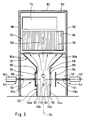
- Exhaust air purification system comprises three in a longitudinal direction 112 in a row arranged heat storage mass container 102, wherein the first this container with 102a, the second, middle of these containers with 102b and the third of these containers will be designated 102c.
- Each of the heat storage mass containers 102 comprises one substantially cuboid heat storage mass chamber 104, which with a heat storage mass 106 is filled.
- This heat storage mass 106 for example, saddle body of a ceramic material which is disordered in the heat storage mass chamber 104 are arranged.
- the heat storage mass 106 honeycomb body includes, which of gas passageways are crossed and prismatic, in particular cuboid, formed are arranged so that they are juxtaposed with their lateral surfaces that in the heat storage mass chamber 104 one or more honeycomb body layers arise, which the gas when passing through the heat storage mass chamber 104 must happen.
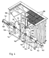
- the heat storage mass 106 rests on gratings 108, which in turn of Cross members 110 are worn (see Fig. 4).
- Each of the heat storage mass chambers 104 opens at its upper end in a in the longitudinal direction 112 of the exhaust air purification system 100 over all three heat storage mass container 102 extending combustion chamber 114, in which one or more burners 116 are arranged, which is a fuel, For example, a combustible gas is supplied to those in the to be cleaned Burn pollutants contained exhaust air (see Fig. 3).
- the exhaust air purification system 100 in stationary operation be operated autothermally, i. without supply of additional fuel.
- the burners 116 are only in the start-up phase of the exhaust air purification system 100 needed to burn in the combustion chamber 114 in To bring gear. Once the stationary operating condition has been reached, the burners can 116 are turned off.
- a thermal combustion can also be a catalytic oxidation be provided in the exhaust air to be purified pollutants.
- a catalytic oxidation be provided in the exhaust air to be purified pollutants.
- the heat storage masses 106 may be arranged.
- the heat storage masses 106 provided with a catalytically active coating or all of one be prepared catalytically active material.
- each heat storage mass container comprises 102 disposed below the heat storage mass chamber 104 Prechamber 118, which has a substantially cuboid lower Section 120, which has a smaller horizontal cross-section than the heat storage mass chamber 104, and an upper portion 122, in which the lower portion 120 opens and which is to the Heat storage mass chamber 104 expanded funnel-shaped.
- the upper portion 122 has a horizontal at its lower end Cross-section corresponding to that of the lower portion 120, and has at its upper end a horizontal cross section, which the horizontal Cross section of the overlying heat storage mass chamber 104 equivalent.
- each prechamber 118 has a first vertical one extending parallel to the longitudinal direction 112 of the exhaust air purification system 100 first side wall 124a, in which a substantially circular access opening 126 is formed, via which the lower portion 120 of Prechamber 118 with a parallel to the longitudinal direction 112 of the exhaust air purification system 100 extending raw gas channel 128 is connected.
- raw gas channel 128 of the exhaust air purification system Through the raw gas channel 128 of the exhaust air purification system is to be cleaned Supplied to exhaust air, which will be referred to below as the raw gas.
- the access opening 126 is the one closed by means of a first poppet valve 130a, which one the access opening 126 surrounding annular valve seat 132 and a the inlet opening 126 covering, circular disk-shaped valve body 134th includes.
- the access opening 126 is vertically aligned so that its surface normal 136a horizontal and thus perpendicular to the vertical mean flow direction 138 is aligned in the heat storage mass 106.
- the valve body 134 of the poppet valve 130a is by means of a movement device 140 between a closed position, in which the valve body 134th rohgaskanalfact on the valve body 134 is substantially gas-tight, and an open position in which the valve body 134 at a distance from the Valve seat 132 is disposed within the raw gas channel 128, movable.
- the movement device 140 may, for example, a pneumatic movement device be, which comprises a pneumatic cylinder 142, in which a (not shown) piston by means of compressed air between two end positions is displaceable.
- the piston is rigid via a connecting rod 144 connected to the valve body 134, so that the valve body 134 of the movement of the piston follows.
- a piston facing away from the free end of Connecting rod 144 between two guide rollers 146 out which um in each case a horizontal, perpendicular to the surface normal 136a of the access opening 126 directed rotation axis rotatably mounted on two vertical beams 148 which are in the vertical direction across the access opening 126 of whose upper edge extend to the lower edge.
- the side wall 124a of the lower forms Section 120 of the pre-chamber 118 has a lateral boundary wall of the Rohgaskanals 128 and forms one at an angle of approximately 45 ° the horizontal inclined side wall 150a has an upper boundary wall of the Crude gas channels 128.
- One of the side wall 124a of the lower portion 120 of the prechamber 118 opposite and substantially parallel to the side wall 124a aligned Side wall 124b is provided with a circular exit opening 152 provided, which with respect to the vertical longitudinal center plane 154 of the prechamber 118 is formed substantially mirror-inverted to the access opening 126 is.
- the surface normal 136 b of the outlet opening 152 which passes through the centroid of the outlet opening 152, parallel to the surface normal 136a through the area centroid of the access opening 126 aligned.
- the surface normal 136b of the outlet opening 152 is thus also horizontal and perpendicular to the mean flow direction 138 of the gas through the Heat storage mass 106 aligned.
- the prechamber 118 is parallel to one to the longitudinal direction 112 of the exhaust air purification system extending clean gas duct 156 connected, which the removal of purified air from the exhaust air purification system 100 serves.
- the side wall 124b of the lower portion forms 120 of the pre-chamber 118 a lateral boundary of the clean gas duct 156, while one at an angle of approximately 45 ° to the horizontal inclined side wall 150b of the upper portion 122 of the pre-chamber 118th forms an upper boundary of the clean gas channel 156.
- the outlet opening is as well as the inlet opening 126 by means of a poppet valve 130b lockable.
- the poppet valve 130b is with respect to the longitudinal center plane 154 of the prechamber 118 is mirror-symmetrical to the poppet valve 130a and includes in particular a movement device 140, a connecting rod 144, a valve seat 132 and annularly surrounding the outlet opening 152 a circular disk-shaped valve body 134, which between a closed position, in which the valve body 134 bears tightly against the valve seat 132, and an open position in which the valve body 134 at a distance from the valve seat 132 is disposed within the clean gas channel 156, is movable.
- the surface normal 136b is the centroid the exit opening 152 by a few centimeters perpendicular to the longitudinal direction of the connecting rods 144 against the surface normal 136a offset the centroid of the access opening 126 to avoid that the connecting rods 144 of the poppet valves 130a and 103b mutually hinder.
- a purge gas such as fresh air
- the heat storage mass container 102, the combustion chamber 114, the raw gas channel 128 and the clean gas channel 156 are in a housing 158 of the exhaust air purification system 100 arranged, the lateral outer walls 160 and its Ceiling wall 162 are provided with a thermal insulation to a the efficiency the exhaust air purification system 100 impairing loss of Heat from the exhaust air purification system 100 in the environment to avoid.
- the exhaust air purification system 100 described above functions as follows:
- raw gas of a raw gas source for example, from a paint shop supplied.
- a first operating state for example, the poppet valve 130a of first heat storage mass container 102a while the poppet valve 130b of the same heat storage mass container 102a is closed, then that the raw gas through the access opening 126 of the first heat storage mass container 102a in its antechamber 118 and from there into the heat storage mass chamber 104 occurs.
- the flow direction of the exhaust air through the exhaust air purification system 100 is in the figures indicated by the arrows 164.
- the prechamber 118 is formed in the heat storage mass 106 of the heat storage mass container 102a doing a very uniform flow with Isobars 168, which are substantially perpendicular to the mean flow direction 138 are aligned by the heat storage mass 106. From a distribution of static pressure in the computer simulation shown in Fig. 7 arrangement is shown in Fig. 8.
- This uniform flow of the heat exchanger material leads to a optimal utilization of the heat exchanger mass 106 and so to an increased Efficiency at a given pressure loss or at a lower Pressure loss at a given efficiency.
- the heat storage mass 106 of the first heat storage mass container 102a is in the first operating state at a relatively high Temperature, so that they the heat storage mass 106 from below to above heated raw gas.
- the thus heated raw gas occurs on upper end of the first heat storage mass container 102a into the combustion chamber 114, whereupon the raw gas in the combustion chamber 114 by thermal Oxidation of the pollutants contained therein is purified.
- the so-formed, pollutant-free clean gas flows (in the line of sight Fig. 1 seen) from right to left through the combustion chamber 114 and via the mouth opening of the second heat storage mass container 102b from above into the heat storage mass chamber 104 thereof.
- the hot clean gas indicates heat this heat storage mass and heats it up so before the hot clean gas the heat storage mass container 102 b through the antechamber 118 and the open poppet valve 130b at the outlet opening 152 of the heat storage mass container 102b leaves.
- the inlet opening 126 of the second heat storage mass container 102b is closed in this operating state by the poppet valve 130a.
- the clean gas from the heat storage mass container 102 b is replaced by the Reingaskanal 156 discharged from the exhaust air purification system and, for example fed to an exhaust chimney.
- the third heat storage mass container 102c becomes in this first operating state by means of a purge gas from the (not shown) purge gas line flushed from bottom to top, in the prechamber 118 and in the heat storage mass chamber 104 of this third heat storage mass container 102c still remaining raw gas residues up in the combustion chamber 114 to transport and clean there by thermal oxidation.
- the flow direction of the purge gas is shown in Fig. 1 by the broken arrow 166.
- the two poppet valves 130a and 130b of the third heat storage mass container 102c are in this flushing state of the heat storage mass container 102c both closed.
- the exhaust air purification system 100 is in a switched second operating state in which the access opening 126 of the second heat storage mass container 102b open and its outlet opening 152 is closed, so that the raw gas now by the second Heat storage mass container 102b flows into the combustion chamber 114 and while passing through the heated in the previous operating state Heat storage mass 106 of the heat storage mass container 102b heated.
- the outlet 152 of the flushed in the previous operating condition heat storage tank 102c is now open, so that the clean gas through the heat storage mass 106 of the third heat storage mass container 102c in the clean gas channel 156 escape while the heat storage mass 106 of the third heat storage mass container 102c heat can.
- the first heat storage mass container 102a is now in the rinsing state, in which both the inlet opening 126 and the outlet opening 152 of this heat storage mass container are closed.
- This second operating state is followed by a third operating state of the exhaust air purification system 100, in which the raw gas through the third heat storage mass container 102c enters the combustion chamber 114, the clean gas through the first heat storage mass container 102a in the clean gas channel 156 exits and the second heat storage mass container 102b is purged.
- this third operating state is a cycle of the exhaust air purification system 100 completed, and a new operating cycle begins again, in which the Exhaust air purification system 100 in the first operating state described above is switched.
Landscapes
- Engineering & Computer Science (AREA)
- Environmental & Geological Engineering (AREA)
- Chemical & Material Sciences (AREA)
- Chemical Kinetics & Catalysis (AREA)
- General Engineering & Computer Science (AREA)
- Analytical Chemistry (AREA)
- General Chemical & Material Sciences (AREA)
- Oil, Petroleum & Natural Gas (AREA)
- Health & Medical Sciences (AREA)
- Mechanical Engineering (AREA)
- Biomedical Technology (AREA)
- Incineration Of Waste (AREA)
- Filtering Of Dispersed Particles In Gases (AREA)
- Treating Waste Gases (AREA)
- Electrical Discharge Machining, Electrochemical Machining, And Combined Machining (AREA)
- Portable Nailing Machines And Staplers (AREA)
- Electrostatic Separation (AREA)
Abstract
Description
- Fig. 1
- einen schematischen Längsschnitt durch die Wärmespeichermassenbehälter einer Abluftreinigungsanlage;
- Fig. 2
- eine perspektivische Darstellung der Abluftreinigungsanlage aus Fig. 1;
- Fig. 3
- einen schematischen vertikalen Schnitt durch einen der Wär-mespeichermassenbehälter der Abluftreinigungsanlage aus den Fig. 1 und 2;
- Fig. 4
- eine perspektivische Darstellung einer Vorkammer des Wärmespeichermassenbehälters aus Fig. 3 mit einer verschließbaren Zutrittsöffnung und einer verschließbaren Austrittsöffnung;
- Fig. 5
- eine schematische perspektivische Darstellung eines Rohgas-kanals und eines Wärmespeichermassenbehälters einer Ab-luftreinigungsanlage gemäß dem Stand der Technik;
- Fig. 6
- eine Darstellung der statischen Druckverteilung in dem Roh-gaskanal und dem Wärmespeichermassenbehälter aus Fig. 5;
- Fig. 7
- eine schematische perspektivische Darstellung eines Rohgas-kanals und eines Wärmespeichermassenbehälters gemäß der Erfindung; und
- Fig. 8
- eine Darstellung der statischen Druckverteilung in dem Roh-gaskanal und dem Wärmespeichermassenbehälter aus Fig. 7.
Claims (18)
- Vorrichtung zur thermischen und/oder katalytischen Reinigung von verbrennbare Bestandteile enthaltender Abluft, umfassend
eine Brennkammer (114),
mindestens zwei von Gasen durchströmbare Wärmespeichermassen (106) enthaltende Behälter (102) zum Erwärmen der zu reinigenden Abluft (Rohgas) vor deren Eintritt in die Brennkammer (114) bzw. zur Aufheizung der Wärmespeichermasse (106) durch die von der Brennkammer (114) kommende gereinigte Abluft (Reingas),
einen Rohgaskanal (128) zum Zuführen des Rohgases zu den Behältern (102) und
einen Reingaskanal (156) zum Abführen des Reingases aus den Behältern (102),
wobei jeder Behälter (102) mindestens eine Zutrittsöffnung (126), durch welche Rohgas aus dem Rohgaskanal (128) in den Behälter (102) eintritt, und mindestens eine Austrittsöffnung (152), durch welche Reingas aus dem Behälter (102) in den Reingaskanal (156) austritt, aufweist, und
wobei die Zutrittsöffnung (126) in eine zwischen der Zutrittsöffnung (126) und der Wärmespeichermasse (106) des Behälters (102) angeordnete Vorkammer (118) mündet,
dadurch gekennzeichnet, daß die Flächennormale (136a) mindestens einer Zutrittsöffnung (126) mindestens eines Behälters (102) quer zu der mittleren Strömungsrichtung (138) durch die Wärmespeichermasse (106) des Behälters (102) ausgerichtet ist und
daß die Vorkammer (118) einen Abschnitt (122) mit einem sich zu der Wärmespeichermasse (106) hin erweiternden Querschnitt aufweist. - Vorrichtung nach Anspruch 1, dadurch gekennzeichnet, daß die Flächennormale (136a) mindestens einer Zutrittsöffnung (126) mindestens eines Behälters (102) im wesentlichen senkrecht zu der mittleren Strömungsrichtung (138) durch die Wärmespeichermasse (106) des Behälters (102) ausgerichtet ist.
- Vorrichtung nach einem der Ansprüche 1 oder 2, dadurch gekennzeichnet, daß die Flächennormale (136a) mindestens einer Zutrittsöffnung (126) mindestens eines Behälters (102) quer, vorzugsweise im wesentlichen senkrecht, zur Vertikalen ausgerichtet ist.
- Vorrichtung nach einem der Ansprüche 1 bis 3, dadurch gekennzeichnet, daß die Flächennormale (136b) mindestens einer Austrittsöffnung (152) mindestens eines Behälters (102) quer zu der mittleren Strömungsrichtung (138) durch die Wärmespeichermasse (106) des Behälters (102) ausgerichtet ist.
- Vorrichtung nach Anspruch 4, dadurch gekennzeichnet, daß die Flächennormale (136b) mindestens einer Austrittsöffnung (152) mindestens eines Behälters (102) im wesentlichen senkrecht zu der mittleren Strömungsrichtung (138) durch die Wärmespeichermasse (106) des Behälters (102) ausgerichtet ist.
- Vorrichtung nach einem der Ansprüche 1 bis 5, dadurch gekennzeichnet, daß die Flächennormale (136b) mindestens einer Austrittsöffnung (152) mindestens eines Behälters (102) quer, vorzugsweise im wesentlichen senkrecht, zur Vertikalen ausgerichtet ist.
- Vorrichtung nach einem der Ansprüche 1 bis 6, dadurch gekennzeichnet, daß mindestens eine Zutrittsöffnung (126) und mindestens eine Austrittsöffnung (152) mindestens eines Behälters (102) bezüglich einer Längsmittelebene (154) des Behälters (102) im wesentlichen symmetrisch zueinander ausgebildet und angeordnet sind.
- Vorrichtung nach einem der Ansprüche 1 bis 7, dadurch gekennzeichnet, daß mindestens eine Zutrittsöffnung (126) und mindestens eine Austrittsöffnung (152) mindestens eines Behälters (102) zueinander parallele Flächennormale (136a, 136b) durch deren jeweilige Flächenschwerpunkte aufweisen.
- Vorrichtung nach einem der Ansprüche 1 bis 8, dadurch gekennzeichnet, daß mindestens eine Zutrittsöffnung (126) und/oder mindestens eine Austrittsöffnung (152) mindestens eines Behälters (102) mittels eines Ventils verschließbar ist.
- Vorrichtung nach Anspruch 9, dadurch gekennzeichnet, daß das Ventil als ein Tellerventil (130a, 130b) ausgebildet ist.
- Vorrichtung nach einem der Ansprüche 9 oder 10, dadurch gekennzeichnet, daß das Ventil einen im wesentlichen scheibenförmigen Ventilkörper (134) aufweist, welcher in seiner Schließstellung im wesentlichen parallel zu der Zutrittsöffnung (126) bzw. im wesentlichen parallel zu der Austrittsöffnung (152) ausgerichtet ist.
- Vorrichtung nach einem der Ansprüche 9 bis 11, dadurch gekennzeichnet, daß das Ventil einen im wesentlichen scheibenförmigen Ventilkörper (134) aufweist, welcher in seiner Offenstellung im wesentlichen parallel zu der Zutrittsöffnung (126) bzw. im wesentlichen parallel zu der Austrittsöffnung (152) ausgerichtet ist.
- Vorrichtung nach einem der Ansprüche 11 oder 12, dadurch gekennzeichnet, daß die Vorrichtung (100) eine Bewegungseinrichtung (140) zum Bewegen des Ventilkörpers (134) von der Offenstellung in die Schließstellung und von der Schließstellung in die Offenstellung umfaßt.
- Vorrichtung nach Anspruch 13, dadurch gekennzeichnet, daß die Bewegungseinrichtung (140) eine pneumatische und/oder hydraulische Bewegungseinrichtung ist.
- Vorrichtung nach einem der Ansprüche 1 bis 14, dadurch gekennzeichnet, daß mindestens eine Austrittsöffnung (152) mindestens eines Behälters (102) in eine zwischen der Austrittsöffnung (152) und der Wärmespeichermasse (106) des Behälters (102) angeordnete Vorkammer (118) mündet.
- Vorrichtung nach einem der Ansprüche 1 bis 15, dadurch gekennzeichnet, daß die Vorkammer (118) einen Abschnitt (120) mit einem im wesentlichen konstanten Querschnitt aufweist.
- Vorrichtung nach Anspruch 16, dadurch gekennzeichnet, daß mindestens eine Zutrittsöffnung (126) und/oder mindestens eine Austrittsöffnung (152) des Behälters (102) in den Abschnitt (120) der Vorkammer (118) mit dem im wesentlichen konstanten Querschnitt mündet.
- Vorrichtung nach einem der Ansprüche 1 bis 17, dadurch gekennzeichnet, daß die Vorkammer (118) einen im wesentlichen rechteckigen Querschnitt aufweist.
Priority Applications (1)
| Application Number | Priority Date | Filing Date | Title |
|---|---|---|---|
| DE50209710.8T DE50209710C5 (de) | 2001-11-14 | 2002-11-14 | Abluftreinigungsvorrichtung |
Applications Claiming Priority (2)
| Application Number | Priority Date | Filing Date | Title |
|---|---|---|---|
| DE20118418U | 2001-11-14 | ||
| DE20118418U DE20118418U1 (de) | 2001-11-14 | 2001-11-14 | Abluftreinigungsvorrichtung |
Publications (3)
| Publication Number | Publication Date |
|---|---|
| EP1312861A2 true EP1312861A2 (de) | 2003-05-21 |
| EP1312861A3 EP1312861A3 (de) | 2003-12-03 |
| EP1312861B1 EP1312861B1 (de) | 2007-03-14 |
Family
ID=7963899
Family Applications (1)
| Application Number | Title | Priority Date | Filing Date |
|---|---|---|---|
| EP02025540A Expired - Lifetime EP1312861B1 (de) | 2001-11-14 | 2002-11-14 | Abluftreinigungsvorrichtung |
Country Status (8)
| Country | Link |
|---|---|
| US (1) | US20030113238A1 (de) |
| EP (1) | EP1312861B1 (de) |
| AT (1) | ATE356958T1 (de) |
| DE (2) | DE20118418U1 (de) |
| DK (1) | DK1312861T3 (de) |
| ES (1) | ES2282358T3 (de) |
| IT (1) | ITTO20020942A1 (de) |
| PT (1) | PT1312861E (de) |
Cited By (1)
| Publication number | Priority date | Publication date | Assignee | Title |
|---|---|---|---|---|
| RU2299089C1 (ru) * | 2005-12-14 | 2007-05-20 | Государственное образовательное учреждение высшего профессионального образования Воронежская государственная технологическая академия | Реактор для каталитической очистки газообразных выбросов |
Families Citing this family (10)
| Publication number | Priority date | Publication date | Assignee | Title |
|---|---|---|---|---|
| DE102004040678B3 (de) * | 2004-08-20 | 2006-02-02 | Müller, Rita | Ventil für thermisch-regenerative Abgasreinigungsanlage und Abgasreinigungsanlage |
| DE102010048308B4 (de) | 2010-10-14 | 2016-06-16 | Ctp Chemisch Thermische Prozesstechnik Gmbh | Vorrichtung zur Reinigung von schadstoffhaltigem Abgas |
| DE102012218776A1 (de) * | 2012-10-15 | 2014-04-17 | Dürr Systems GmbH | Anlage für das thermische Behandeln von gasförmigem Medium |
| DE102015205547A1 (de) | 2015-02-26 | 2016-09-01 | Dürr Systems GmbH | Formkörper zum Temperieren eines Fluids und mit solchen Formkörpern aufgebauter Wärmetauscher |
| DE102015205552A1 (de) | 2015-02-26 | 2016-09-01 | Dürr Systems GmbH | Formkörper zum Temperieren eines Fluids und mit solchen Formkörpern aufgebauter Wärmetauscher |
| CN111503649B (zh) * | 2020-04-28 | 2022-03-18 | 聊城集众环保科技有限公司 | 一种吸附浓缩型蓄热式催化燃烧装置 |
| DE102020113657A1 (de) | 2020-05-20 | 2021-11-25 | Dürr Systems Ag | Thermische abluftreinigungsvorrichtung |
| JP7158095B2 (ja) * | 2020-10-27 | 2022-10-21 | 株式会社Thermal Power Plant Engineering | 蓄熱燃焼脱臭装置 |
| CN116241895A (zh) * | 2022-12-15 | 2023-06-09 | 安徽国科环保设备制造有限公司 | 一种voc气体热力燃烧炉 |
| CN116357985A (zh) * | 2022-12-23 | 2023-06-30 | 武汉能望科技有限公司 | 适应有机废气浓度大范围变化的燃烧器和废气燃烧装置 |
Citations (1)
| Publication number | Priority date | Publication date | Assignee | Title |
|---|---|---|---|---|
| DE19519868A1 (de) | 1995-05-31 | 1996-12-05 | Duerr Gmbh & Co | Einrichtung zur thermischen Abluftreinigung |
Family Cites Families (12)
| Publication number | Priority date | Publication date | Assignee | Title |
|---|---|---|---|---|
| US4658853A (en) | 1985-01-09 | 1987-04-21 | Regenerative Environmental Equipment Co., Inc. | Anti-leak valving system |
| AT387643B (de) | 1987-05-22 | 1989-02-27 | Julia Pavlovna Veber | Einrichtung fuer die katalytische nachverbrennung von schadstoffen aus einer ventilationseinrichtung |
| DE8714715U1 (de) | 1987-11-05 | 1988-01-21 | Douglas, Jürgen, 2000 Hamburg | Informations- und Vortragsmagazin |
| US5016547A (en) * | 1990-05-04 | 1991-05-21 | Salem Industries, Inc. | Regenerative incinerator |
| IT1259150B (it) * | 1992-09-07 | 1996-03-11 | Orv Spa | Termodistruttore perfezionato |
| AT402697B (de) * | 1995-08-17 | 1997-07-25 | Schedler Johannes | Verfahren zur thermischen abreinigung von regenerativen nachverbrennungsanlage ohne schastoffreisetzung und ohne unterbrechung des hauptgasstrommes |
| DE19617790A1 (de) * | 1996-05-03 | 1997-11-13 | Freimut Joachim Marold | Verfahren und Vorrichtung zur regenerativen Nachverbrennung und schaltbarer Verteiler für Fluide |
| DE19637090C1 (de) | 1996-09-12 | 1997-12-18 | Duerr Systems Gmbh | Industrielle Abluftreinigungsanlage |
| AU8069198A (en) * | 1997-06-13 | 1998-12-30 | Smith Engineering Company | Pollutant reduction catalyst in thermal oxidizer |
| DE19747905C1 (de) * | 1997-10-30 | 1999-01-28 | Chemisch Thermische Prozestech | Vorrichtung zur Reinigung von schadstoffhaltigem Abgas |
| US6039927A (en) * | 1997-11-04 | 2000-03-21 | Greco; Richard | Valve system for regenerative thermal oxidizers |
| EP1134018A1 (de) | 2000-03-15 | 2001-09-19 | Trinity Industrial Corporation | Vorrichtung zur Abgasbehandlung |
-
2001
- 2001-11-14 DE DE20118418U patent/DE20118418U1/de not_active Expired - Lifetime
-
2002
- 2002-10-30 IT IT000942A patent/ITTO20020942A1/it unknown
- 2002-11-12 US US10/292,308 patent/US20030113238A1/en not_active Abandoned
- 2002-11-14 AT AT02025540T patent/ATE356958T1/de active
- 2002-11-14 EP EP02025540A patent/EP1312861B1/de not_active Expired - Lifetime
- 2002-11-14 DE DE50209710.8T patent/DE50209710C5/de not_active Expired - Lifetime
- 2002-11-14 ES ES02025540T patent/ES2282358T3/es not_active Expired - Lifetime
- 2002-11-14 DK DK02025540T patent/DK1312861T3/da active
- 2002-11-14 PT PT02025540T patent/PT1312861E/pt unknown
Patent Citations (1)
| Publication number | Priority date | Publication date | Assignee | Title |
|---|---|---|---|---|
| DE19519868A1 (de) | 1995-05-31 | 1996-12-05 | Duerr Gmbh & Co | Einrichtung zur thermischen Abluftreinigung |
Cited By (1)
| Publication number | Priority date | Publication date | Assignee | Title |
|---|---|---|---|---|
| RU2299089C1 (ru) * | 2005-12-14 | 2007-05-20 | Государственное образовательное учреждение высшего профессионального образования Воронежская государственная технологическая академия | Реактор для каталитической очистки газообразных выбросов |
Also Published As
| Publication number | Publication date |
|---|---|
| DE50209710C5 (de) | 2018-10-04 |
| ES2282358T3 (es) | 2007-10-16 |
| EP1312861B1 (de) | 2007-03-14 |
| DE20118418U1 (de) | 2002-03-21 |
| EP1312861A3 (de) | 2003-12-03 |
| ITTO20020942A1 (it) | 2003-05-15 |
| ATE356958T1 (de) | 2007-04-15 |
| PT1312861E (pt) | 2007-04-30 |
| DE50209710D1 (de) | 2007-04-26 |
| DK1312861T3 (da) | 2007-07-16 |
| US20030113238A1 (en) | 2003-06-19 |
Similar Documents
| Publication | Publication Date | Title |
|---|---|---|
| DE2327983B2 (de) | Waagerechter verkokungsofen mit querregeneratoren | |
| EP1312861B1 (de) | Abluftreinigungsvorrichtung | |
| DE69530296T2 (de) | Hochtemperatur gasgenerator | |
| DE2423799A1 (de) | Thermische verbrennungsvorrichtung mit waermerueckgewinnung | |
| DE3322119A1 (de) | Verbrennungsanlage mit regenerativem waermeaustauscher | |
| EP0745806A2 (de) | Einrichtung zur thermischen Abluftreinigung | |
| AT506459B1 (de) | Vorrichtung und verfahren zur reinigung von schadstoffhaltigem abgas | |
| DE2636374A1 (de) | Verfahren und vorrichtung zur reinigung von abgas | |
| WO1988006256A1 (fr) | Agencement a grilles, en particulier pour grilles pivotantes en gradins | |
| DE19905733A1 (de) | Verfahren und Anlage zur Reinigung von mit Stickoxiden beladenen Abgasen | |
| DE19747905C1 (de) | Vorrichtung zur Reinigung von schadstoffhaltigem Abgas | |
| DE69906296T2 (de) | Ringkammerofen mit tubularer zentralgasströmung | |
| DE2802574A1 (de) | Vorrichtung zur entfernung von verunreinigungen aus gasen mit inneren umgehungswegen | |
| DE3826832A1 (de) | Veraschungsvorrichtung mit verbessertem wandaufbau | |
| DE19643821C1 (de) | Anlage zur Reinigung von Gasen | |
| EP1135652B1 (de) | Regenerative nachverbrennungsvorrichtung | |
| EP0091471B1 (de) | Kokslöscheinrichtung | |
| DE928828C (de) | Regenerativ-Koksofen mit senkrechten Heizzuegen | |
| DE3447267A1 (de) | Vorrichtung zum erhitzen von chargiergut | |
| DE2134634A1 (de) | Vorrichtung zum thermischen nachverbrennen von abluft aus industrieanlagen | |
| DE867087C (de) | Vorrichtung zum Regeln des Zuges in den Einzelregeneratoren fuer waagerechte, halbteilig beheizte Koksoefen | |
| DE2758327A1 (de) | Luftverteiler | |
| WO1997035149A1 (de) | Vorrichtung zur thermischen abgasbehandlung, inbesondere von oxidierbaren schwelgasen | |
| DE1045175B (de) | Vorrichtung zur katalytischen Oxydation giftiger und schaedlicher Abgase von Brennkraftmaschinen | |
| DE3611953A1 (de) | Einrichtung zum gesteuerten abzug von fliessfaehigem schuettgut an der unterseite einer schuettgutsaeule, insbesondere eines wanderbettfilters |
Legal Events
| Date | Code | Title | Description |
|---|---|---|---|
| PUAI | Public reference made under article 153(3) epc to a published international application that has entered the european phase |
Free format text: ORIGINAL CODE: 0009012 |
|
| AK | Designated contracting states |
Designated state(s): AT BE BG CH CY CZ DE DK EE ES FI FR GB GR IE IT LI LU MC NL PT SE SK TR |
|
| AX | Request for extension of the european patent |
Extension state: AL LT LV MK RO SI |
|
| RIN1 | Information on inventor provided before grant (corrected) |
Inventor name: HUMMEL, BERTRAM Inventor name: BHATNAGAR, SATPAL Inventor name: RIEDER, ERHARD Inventor name: KOENIG, BERND |
|
| PUAL | Search report despatched |
Free format text: ORIGINAL CODE: 0009013 |
|
| AK | Designated contracting states |
Kind code of ref document: A3 Designated state(s): AT BE BG CH CY CZ DE DK EE ES FI FR GB GR IE IT LI LU MC NL PT SE SK TR |
|
| AX | Request for extension of the european patent |
Extension state: AL LT LV MK RO SI |
|
| 17P | Request for examination filed |
Effective date: 20040504 |
|
| AKX | Designation fees paid |
Designated state(s): AT BE BG CH CY CZ DE DK EE ES FI FR GB GR IE IT LI LU MC NL PT SE SK TR |
|
| RAP1 | Party data changed (applicant data changed or rights of an application transferred) |
Owner name: DUERR SYSTEMS GMBH |
|
| GRAP | Despatch of communication of intention to grant a patent |
Free format text: ORIGINAL CODE: EPIDOSNIGR1 |
|
| GRAS | Grant fee paid |
Free format text: ORIGINAL CODE: EPIDOSNIGR3 |
|
| GRAA | (expected) grant |
Free format text: ORIGINAL CODE: 0009210 |
|
| AK | Designated contracting states |
Kind code of ref document: B1 Designated state(s): AT BE BG CH CY CZ DE DK EE ES FI FR GB GR IE IT LI LU MC NL PT SE SK TR |
|
| REG | Reference to a national code |
Ref country code: GB Ref legal event code: FG4D Free format text: NOT ENGLISH |
|
| REG | Reference to a national code |
Ref country code: CH Ref legal event code: EP |
|
| REF | Corresponds to: |
Ref document number: 50209710 Country of ref document: DE Date of ref document: 20070426 Kind code of ref document: P |
|
| REG | Reference to a national code |
Ref country code: PT Ref legal event code: SC4A Free format text: AVAILABILITY OF NATIONAL TRANSLATION Effective date: 20070409 |
|
| REG | Reference to a national code |
Ref country code: IE Ref legal event code: FG4D Free format text: LANGUAGE OF EP DOCUMENT: GERMAN |
|
| REG | Reference to a national code |
Ref country code: CH Ref legal event code: NV Representative=s name: ISLER & PEDRAZZINI AG |
|
| GBT | Gb: translation of ep patent filed (gb section 77(6)(a)/1977) |
Effective date: 20070508 |
|
| REG | Reference to a national code |
Ref country code: SE Ref legal event code: TRGR |
|
| REG | Reference to a national code |
Ref country code: GR Ref legal event code: EP Ref document number: 20070401601 Country of ref document: GR |
|
| REG | Reference to a national code |
Ref country code: DK Ref legal event code: T3 |
|
| ET | Fr: translation filed | ||
| REG | Reference to a national code |
Ref country code: CH Ref legal event code: PCAR Free format text: ISLER & PEDRAZZINI AG;POSTFACH 1772;8027 ZUERICH (CH) |
|
| REG | Reference to a national code |
Ref country code: ES Ref legal event code: FG2A Ref document number: 2282358 Country of ref document: ES Kind code of ref document: T3 |
|
| PLBE | No opposition filed within time limit |
Free format text: ORIGINAL CODE: 0009261 |
|
| STAA | Information on the status of an ep patent application or granted ep patent |
Free format text: STATUS: NO OPPOSITION FILED WITHIN TIME LIMIT |
|
| 26N | No opposition filed |
Effective date: 20071217 |
|
| PG25 | Lapsed in a contracting state [announced via postgrant information from national office to epo] |
Ref country code: MC Free format text: LAPSE BECAUSE OF NON-PAYMENT OF DUE FEES Effective date: 20071130 |
|
| PG25 | Lapsed in a contracting state [announced via postgrant information from national office to epo] |
Ref country code: CY Free format text: LAPSE BECAUSE OF FAILURE TO SUBMIT A TRANSLATION OF THE DESCRIPTION OR TO PAY THE FEE WITHIN THE PRESCRIBED TIME-LIMIT Effective date: 20070314 |
|
| PG25 | Lapsed in a contracting state [announced via postgrant information from national office to epo] |
Ref country code: BG Free format text: LAPSE BECAUSE OF FAILURE TO SUBMIT A TRANSLATION OF THE DESCRIPTION OR TO PAY THE FEE WITHIN THE PRESCRIBED TIME-LIMIT Effective date: 20070614 |
|
| REG | Reference to a national code |
Ref country code: DE Ref legal event code: R008 Ref document number: 50209710 Country of ref document: DE |
|
| REG | Reference to a national code |
Ref country code: DE Ref legal event code: R039 Ref document number: 50209710 Country of ref document: DE Effective date: 20110725 |
|
| REG | Reference to a national code |
Ref country code: DE Ref legal event code: R097 Ref document number: 50209710 Country of ref document: DE |
|
| REG | Reference to a national code |
Ref country code: DE Ref legal event code: R040 Ref document number: 50209710 Country of ref document: DE Effective date: 20130905 |
|
| REG | Reference to a national code |
Ref country code: DE Ref legal event code: R046 Ref document number: 50209710 Country of ref document: DE Effective date: 20130928 |
|
| REG | Reference to a national code |
Ref country code: DE Ref legal event code: R050 Ref document number: 50209710 Country of ref document: DE |
|
| REG | Reference to a national code |
Ref country code: DE Ref legal event code: R050 Ref document number: 50209710 Country of ref document: DE Effective date: 20141017 |
|
| REG | Reference to a national code |
Ref country code: DE Ref legal event code: R206 Ref document number: 50209710 Country of ref document: DE Effective date: 20141211 |
|
| REG | Reference to a national code |
Ref country code: DE Ref legal event code: R082 Ref document number: 50209710 Country of ref document: DE Representative=s name: HOEGER, STELLRECHT & PARTNER PATENTANWAELTE MB, DE |
|
| REG | Reference to a national code |
Ref country code: FR Ref legal event code: PLFP Year of fee payment: 14 |
|
| REG | Reference to a national code |
Ref country code: DE Ref legal event code: R008 Ref document number: 50209710 Country of ref document: DE Ref country code: DE Ref legal event code: R039 Ref document number: 50209710 Country of ref document: DE |
|
| REG | Reference to a national code |
Ref country code: DE Ref legal event code: R082 Ref document number: 50209710 Country of ref document: DE Representative=s name: HOEGER, STELLRECHT & PARTNER PATENTANWAELTE MB, DE Ref country code: DE Ref legal event code: R081 Ref document number: 50209710 Country of ref document: DE Owner name: DUERR SYSTEMS AG, DE Free format text: FORMER OWNER: DUERR SYSTEMS GMBH, 74321 BIETIGHEIM-BISSINGEN, DE |
|
| REG | Reference to a national code |
Ref country code: FR Ref legal event code: PLFP Year of fee payment: 15 |
|
| REG | Reference to a national code |
Ref country code: FR Ref legal event code: PLFP Year of fee payment: 16 |
|
| PGFP | Annual fee paid to national office [announced via postgrant information from national office to epo] |
Ref country code: LU Payment date: 20171120 Year of fee payment: 16 |
|
| PGFP | Annual fee paid to national office [announced via postgrant information from national office to epo] |
Ref country code: CZ Payment date: 20171024 Year of fee payment: 16 Ref country code: FI Payment date: 20171121 Year of fee payment: 16 Ref country code: TR Payment date: 20171110 Year of fee payment: 16 Ref country code: EE Payment date: 20171116 Year of fee payment: 16 Ref country code: SK Payment date: 20171113 Year of fee payment: 16 Ref country code: DK Payment date: 20171122 Year of fee payment: 16 |
|
| PGFP | Annual fee paid to national office [announced via postgrant information from national office to epo] |
Ref country code: CH Payment date: 20171120 Year of fee payment: 16 Ref country code: SE Payment date: 20171120 Year of fee payment: 16 Ref country code: PT Payment date: 20171110 Year of fee payment: 16 Ref country code: GR Payment date: 20171114 Year of fee payment: 16 Ref country code: GB Payment date: 20171123 Year of fee payment: 16 Ref country code: IE Payment date: 20171121 Year of fee payment: 16 |
|
| REG | Reference to a national code |
Ref country code: DE Ref legal event code: R043 Ref document number: 50209710 Country of ref document: DE |
|
| REG | Reference to a national code |
Ref country code: DE Ref legal event code: R206 Ref document number: 50209710 Country of ref document: DE |
|
| PGFP | Annual fee paid to national office [announced via postgrant information from national office to epo] |
Ref country code: NL Payment date: 20181120 Year of fee payment: 17 |
|
| REG | Reference to a national code |
Ref country code: EE Ref legal event code: MM4A Ref document number: E001415 Country of ref document: EE Effective date: 20181130 |
|
| REG | Reference to a national code |
Ref country code: DK Ref legal event code: EBP Effective date: 20181130 |
|
| REG | Reference to a national code |
Ref country code: CH Ref legal event code: PL |
|
| REG | Reference to a national code |
Ref country code: SE Ref legal event code: EUG |
|
| GBPC | Gb: european patent ceased through non-payment of renewal fee |
Effective date: 20181114 |
|
| REG | Reference to a national code |
Ref country code: DE Ref legal event code: R082 Ref document number: 50209710 Country of ref document: DE Representative=s name: HOEGER, STELLRECHT & PARTNER PATENTANWAELTE MB, DE |
|
| PG25 | Lapsed in a contracting state [announced via postgrant information from national office to epo] |
Ref country code: CZ Free format text: LAPSE BECAUSE OF NON-PAYMENT OF DUE FEES Effective date: 20181114 Ref country code: SE Free format text: LAPSE BECAUSE OF NON-PAYMENT OF DUE FEES Effective date: 20181115 Ref country code: PT Free format text: LAPSE BECAUSE OF NON-PAYMENT OF DUE FEES Effective date: 20190514 Ref country code: FI Free format text: LAPSE BECAUSE OF NON-PAYMENT OF DUE FEES Effective date: 20181114 Ref country code: LU Free format text: LAPSE BECAUSE OF NON-PAYMENT OF DUE FEES Effective date: 20181114 |
|
| REG | Reference to a national code |
Ref country code: SK Ref legal event code: MM4A Ref document number: E 1956 Country of ref document: SK Effective date: 20181114 |
|
| REG | Reference to a national code |
Ref country code: IE Ref legal event code: MM4A |
|
| PG25 | Lapsed in a contracting state [announced via postgrant information from national office to epo] |
Ref country code: EE Free format text: LAPSE BECAUSE OF NON-PAYMENT OF DUE FEES Effective date: 20181130 Ref country code: GR Free format text: LAPSE BECAUSE OF NON-PAYMENT OF DUE FEES Effective date: 20190605 Ref country code: SK Free format text: LAPSE BECAUSE OF NON-PAYMENT OF DUE FEES Effective date: 20181114 Ref country code: LI Free format text: LAPSE BECAUSE OF NON-PAYMENT OF DUE FEES Effective date: 20181130 Ref country code: CH Free format text: LAPSE BECAUSE OF NON-PAYMENT OF DUE FEES Effective date: 20181130 |
|
| PG25 | Lapsed in a contracting state [announced via postgrant information from national office to epo] |
Ref country code: DK Free format text: LAPSE BECAUSE OF NON-PAYMENT OF DUE FEES Effective date: 20181130 Ref country code: IE Free format text: LAPSE BECAUSE OF NON-PAYMENT OF DUE FEES Effective date: 20181114 |
|
| PG25 | Lapsed in a contracting state [announced via postgrant information from national office to epo] |
Ref country code: GB Free format text: LAPSE BECAUSE OF NON-PAYMENT OF DUE FEES Effective date: 20181114 |
|
| PGFP | Annual fee paid to national office [announced via postgrant information from national office to epo] |
Ref country code: ES Payment date: 20191220 Year of fee payment: 18 |
|
| PGFP | Annual fee paid to national office [announced via postgrant information from national office to epo] |
Ref country code: AT Payment date: 20191121 Year of fee payment: 18 |
|
| REG | Reference to a national code |
Ref country code: NL Ref legal event code: MM Effective date: 20191201 |
|
| REG | Reference to a national code |
Ref country code: BE Ref legal event code: MM Effective date: 20191130 |
|
| PG25 | Lapsed in a contracting state [announced via postgrant information from national office to epo] |
Ref country code: NL Free format text: LAPSE BECAUSE OF NON-PAYMENT OF DUE FEES Effective date: 20191201 |
|
| PG25 | Lapsed in a contracting state [announced via postgrant information from national office to epo] |
Ref country code: BE Free format text: LAPSE BECAUSE OF NON-PAYMENT OF DUE FEES Effective date: 20191130 |
|
| REG | Reference to a national code |
Ref country code: AT Ref legal event code: MM01 Ref document number: 356958 Country of ref document: AT Kind code of ref document: T Effective date: 20201114 |
|
| PG25 | Lapsed in a contracting state [announced via postgrant information from national office to epo] |
Ref country code: AT Free format text: LAPSE BECAUSE OF NON-PAYMENT OF DUE FEES Effective date: 20201114 |
|
| PGFP | Annual fee paid to national office [announced via postgrant information from national office to epo] |
Ref country code: DE Payment date: 20211118 Year of fee payment: 20 Ref country code: FR Payment date: 20211119 Year of fee payment: 20 |
|
| REG | Reference to a national code |
Ref country code: ES Ref legal event code: FD2A Effective date: 20220201 |
|
| PGFP | Annual fee paid to national office [announced via postgrant information from national office to epo] |
Ref country code: IT Payment date: 20211122 Year of fee payment: 20 |
|
| PG25 | Lapsed in a contracting state [announced via postgrant information from national office to epo] |
Ref country code: ES Free format text: LAPSE BECAUSE OF NON-PAYMENT OF DUE FEES Effective date: 20201115 |
|
| PG25 | Lapsed in a contracting state [announced via postgrant information from national office to epo] |
Ref country code: TR Free format text: LAPSE BECAUSE OF NON-PAYMENT OF DUE FEES Effective date: 20181114 |
|
| REG | Reference to a national code |
Ref country code: DE Ref legal event code: R071 Ref document number: 50209710 Country of ref document: DE |