EP1312776A2 - Système pour la purification de gaz d'échappement - Google Patents
Système pour la purification de gaz d'échappement Download PDFInfo
- Publication number
- EP1312776A2 EP1312776A2 EP02025431A EP02025431A EP1312776A2 EP 1312776 A2 EP1312776 A2 EP 1312776A2 EP 02025431 A EP02025431 A EP 02025431A EP 02025431 A EP02025431 A EP 02025431A EP 1312776 A2 EP1312776 A2 EP 1312776A2
- Authority
- EP
- European Patent Office
- Prior art keywords
- exhaust gas
- passage
- dpf
- purification system
- gas purification
- Prior art date
- Legal status (The legal status is an assumption and is not a legal conclusion. Google has not performed a legal analysis and makes no representation as to the accuracy of the status listed.)
- Withdrawn
Links
- 238000000746 purification Methods 0.000 title claims abstract description 149
- 238000007254 oxidation reaction Methods 0.000 claims abstract description 276
- 230000003647 oxidation Effects 0.000 claims abstract description 262
- 239000013618 particulate matter Substances 0.000 claims abstract description 211
- 230000002265 prevention Effects 0.000 claims abstract description 19
- 239000003054 catalyst Substances 0.000 claims description 246
- 230000002093 peripheral effect Effects 0.000 claims description 115
- 238000011144 upstream manufacturing Methods 0.000 claims description 73
- 239000006096 absorbing agent Substances 0.000 claims description 25
- 229910052751 metal Inorganic materials 0.000 claims description 24
- 239000002184 metal Substances 0.000 claims description 24
- 230000007423 decrease Effects 0.000 claims description 19
- 238000007789 sealing Methods 0.000 claims description 16
- 239000000919 ceramic Substances 0.000 claims description 15
- 239000000463 material Substances 0.000 claims description 13
- 239000007787 solid Substances 0.000 claims description 11
- 238000009413 insulation Methods 0.000 claims description 5
- 229910010271 silicon carbide Inorganic materials 0.000 claims description 3
- HBMJWWWQQXIZIP-UHFFFAOYSA-N silicon carbide Chemical compound [Si+]#[C-] HBMJWWWQQXIZIP-UHFFFAOYSA-N 0.000 claims description 3
- 229910052581 Si3N4 Inorganic materials 0.000 claims description 2
- HQVNEWCFYHHQES-UHFFFAOYSA-N silicon nitride Chemical compound N12[Si]34N5[Si]62N3[Si]51N64 HQVNEWCFYHHQES-UHFFFAOYSA-N 0.000 claims description 2
- 230000006378 damage Effects 0.000 abstract description 34
- 238000009826 distribution Methods 0.000 abstract description 32
- 238000002844 melting Methods 0.000 abstract description 28
- 230000008018 melting Effects 0.000 abstract description 28
- 239000007789 gas Substances 0.000 description 373
- 239000000203 mixture Substances 0.000 description 79
- 238000011069 regeneration method Methods 0.000 description 71
- 230000008929 regeneration Effects 0.000 description 70
- MWUXSHHQAYIFBG-UHFFFAOYSA-N nitrogen oxide Inorganic materials O=[N] MWUXSHHQAYIFBG-UHFFFAOYSA-N 0.000 description 51
- 238000002485 combustion reaction Methods 0.000 description 47
- JCXJVPUVTGWSNB-UHFFFAOYSA-N nitrogen dioxide Inorganic materials O=[N]=O JCXJVPUVTGWSNB-UHFFFAOYSA-N 0.000 description 30
- MGWGWNFMUOTEHG-UHFFFAOYSA-N 4-(3,5-dimethylphenyl)-1,3-thiazol-2-amine Chemical compound CC1=CC(C)=CC(C=2N=C(N)SC=2)=C1 MGWGWNFMUOTEHG-UHFFFAOYSA-N 0.000 description 29
- 230000000694 effects Effects 0.000 description 21
- 238000009792 diffusion process Methods 0.000 description 14
- 238000009825 accumulation Methods 0.000 description 13
- 239000000853 adhesive Substances 0.000 description 9
- 230000001070 adhesive effect Effects 0.000 description 9
- 230000005855 radiation Effects 0.000 description 9
- 229910052878 cordierite Inorganic materials 0.000 description 8
- JSKIRARMQDRGJZ-UHFFFAOYSA-N dimagnesium dioxido-bis[(1-oxido-3-oxo-2,4,6,8,9-pentaoxa-1,3-disila-5,7-dialuminabicyclo[3.3.1]nonan-7-yl)oxy]silane Chemical compound [Mg++].[Mg++].[O-][Si]([O-])(O[Al]1O[Al]2O[Si](=O)O[Si]([O-])(O1)O2)O[Al]1O[Al]2O[Si](=O)O[Si]([O-])(O1)O2 JSKIRARMQDRGJZ-UHFFFAOYSA-N 0.000 description 8
- 230000001590 oxidative effect Effects 0.000 description 7
- BASFCYQUMIYNBI-UHFFFAOYSA-N platinum Chemical compound [Pt] BASFCYQUMIYNBI-UHFFFAOYSA-N 0.000 description 7
- 229920001296 polysiloxane Polymers 0.000 description 7
- 238000005273 aeration Methods 0.000 description 6
- PNEYBMLMFCGWSK-UHFFFAOYSA-N aluminium oxide Inorganic materials [O-2].[O-2].[O-2].[Al+3].[Al+3] PNEYBMLMFCGWSK-UHFFFAOYSA-N 0.000 description 6
- 230000015572 biosynthetic process Effects 0.000 description 6
- 238000006243 chemical reaction Methods 0.000 description 6
- 230000006866 deterioration Effects 0.000 description 6
- 238000010586 diagram Methods 0.000 description 6
- 230000002159 abnormal effect Effects 0.000 description 5
- 239000011248 coating agent Substances 0.000 description 5
- 238000000576 coating method Methods 0.000 description 5
- 230000003247 decreasing effect Effects 0.000 description 5
- 238000010438 heat treatment Methods 0.000 description 5
- 150000002739 metals Chemical class 0.000 description 5
- 238000003860 storage Methods 0.000 description 5
- 229910000505 Al2TiO5 Inorganic materials 0.000 description 4
- CURLTUGMZLYLDI-UHFFFAOYSA-N Carbon dioxide Chemical compound O=C=O CURLTUGMZLYLDI-UHFFFAOYSA-N 0.000 description 4
- 230000003213 activating effect Effects 0.000 description 4
- 230000003197 catalytic effect Effects 0.000 description 4
- 238000001914 filtration Methods 0.000 description 4
- 239000000446 fuel Substances 0.000 description 4
- 238000000265 homogenisation Methods 0.000 description 4
- AABBHSMFGKYLKE-SNAWJCMRSA-N propan-2-yl (e)-but-2-enoate Chemical compound C\C=C\C(=O)OC(C)C AABBHSMFGKYLKE-SNAWJCMRSA-N 0.000 description 4
- QVGXLLKOCUKJST-UHFFFAOYSA-N atomic oxygen Chemical compound [O] QVGXLLKOCUKJST-UHFFFAOYSA-N 0.000 description 3
- 229910002092 carbon dioxide Inorganic materials 0.000 description 3
- 229910010293 ceramic material Inorganic materials 0.000 description 3
- CETPSERCERDGAM-UHFFFAOYSA-N ceric oxide Chemical compound O=[Ce]=O CETPSERCERDGAM-UHFFFAOYSA-N 0.000 description 3
- 229910000422 cerium(IV) oxide Inorganic materials 0.000 description 3
- 230000008859 change Effects 0.000 description 3
- 230000014759 maintenance of location Effects 0.000 description 3
- 230000004048 modification Effects 0.000 description 3
- 238000012986 modification Methods 0.000 description 3
- 238000000465 moulding Methods 0.000 description 3
- 239000001301 oxygen Substances 0.000 description 3
- 229910052760 oxygen Inorganic materials 0.000 description 3
- 229910052697 platinum Inorganic materials 0.000 description 3
- 230000002123 temporal effect Effects 0.000 description 3
- 239000004215 Carbon black (E152) Substances 0.000 description 2
- UGFAIRIUMAVXCW-UHFFFAOYSA-N Carbon monoxide Chemical compound [O+]#[C-] UGFAIRIUMAVXCW-UHFFFAOYSA-N 0.000 description 2
- 229910045601 alloy Inorganic materials 0.000 description 2
- 239000000956 alloy Substances 0.000 description 2
- 229910052782 aluminium Inorganic materials 0.000 description 2
- XAGFODPZIPBFFR-UHFFFAOYSA-N aluminium Chemical compound [Al] XAGFODPZIPBFFR-UHFFFAOYSA-N 0.000 description 2
- 229910052799 carbon Inorganic materials 0.000 description 2
- 229910002091 carbon monoxide Inorganic materials 0.000 description 2
- 230000001276 controlling effect Effects 0.000 description 2
- 230000002542 deteriorative effect Effects 0.000 description 2
- 230000008030 elimination Effects 0.000 description 2
- 238000003379 elimination reaction Methods 0.000 description 2
- 239000000835 fiber Substances 0.000 description 2
- 230000020169 heat generation Effects 0.000 description 2
- 229930195733 hydrocarbon Natural products 0.000 description 2
- 150000002430 hydrocarbons Chemical class 0.000 description 2
- 230000006872 improvement Effects 0.000 description 2
- 238000003780 insertion Methods 0.000 description 2
- 230000037431 insertion Effects 0.000 description 2
- 238000009434 installation Methods 0.000 description 2
- 150000003254 radicals Chemical group 0.000 description 2
- 230000009467 reduction Effects 0.000 description 2
- 239000000126 substance Substances 0.000 description 2
- 239000000725 suspension Substances 0.000 description 2
- 230000003685 thermal hair damage Effects 0.000 description 2
- 230000008646 thermal stress Effects 0.000 description 2
- 229910000838 Al alloy Inorganic materials 0.000 description 1
- 101100224414 Caenorhabditis elegans dpf-1 gene Proteins 0.000 description 1
- GWGQWFHTAOMUBD-UHFFFAOYSA-N [[3-[bis(phosphonomethyl)amino]-2-hydroxypropyl]-(phosphonomethyl)amino]methylphosphonic acid Chemical compound OP(=O)(O)CN(CP(O)(O)=O)CC(O)CN(CP(O)(O)=O)CP(O)(O)=O GWGQWFHTAOMUBD-UHFFFAOYSA-N 0.000 description 1
- 238000011001 backwashing Methods 0.000 description 1
- 230000004888 barrier function Effects 0.000 description 1
- 230000005540 biological transmission Effects 0.000 description 1
- 239000001569 carbon dioxide Substances 0.000 description 1
- 238000004891 communication Methods 0.000 description 1
- 230000003111 delayed effect Effects 0.000 description 1
- 238000005516 engineering process Methods 0.000 description 1
- 238000002474 experimental method Methods 0.000 description 1
- -1 for instance Substances 0.000 description 1
- 230000008642 heat stress Effects 0.000 description 1
- 238000010030 laminating Methods 0.000 description 1
- 238000004519 manufacturing process Methods 0.000 description 1
- 239000007769 metal material Substances 0.000 description 1
- 238000000034 method Methods 0.000 description 1
- 150000004767 nitrides Chemical class 0.000 description 1
- 230000000644 propagated effect Effects 0.000 description 1
- 230000001172 regenerating effect Effects 0.000 description 1
- 230000001105 regulatory effect Effects 0.000 description 1
- 239000010935 stainless steel Substances 0.000 description 1
- 229910001220 stainless steel Inorganic materials 0.000 description 1
- 238000012546 transfer Methods 0.000 description 1
Images


Classifications
-
- F—MECHANICAL ENGINEERING; LIGHTING; HEATING; WEAPONS; BLASTING
- F01—MACHINES OR ENGINES IN GENERAL; ENGINE PLANTS IN GENERAL; STEAM ENGINES
- F01N—GAS-FLOW SILENCERS OR EXHAUST APPARATUS FOR MACHINES OR ENGINES IN GENERAL; GAS-FLOW SILENCERS OR EXHAUST APPARATUS FOR INTERNAL COMBUSTION ENGINES
- F01N9/00—Electrical control of exhaust gas treating apparatus
- F01N9/002—Electrical control of exhaust gas treating apparatus of filter regeneration, e.g. detection of clogging
-
- B—PERFORMING OPERATIONS; TRANSPORTING
- B01—PHYSICAL OR CHEMICAL PROCESSES OR APPARATUS IN GENERAL
- B01D—SEPARATION
- B01D46/00—Filters or filtering processes specially modified for separating dispersed particles from gases or vapours
- B01D46/24—Particle separators, e.g. dust precipitators, using rigid hollow filter bodies
- B01D46/2403—Particle separators, e.g. dust precipitators, using rigid hollow filter bodies characterised by the physical shape or structure of the filtering element
- B01D46/2418—Honeycomb filters
- B01D46/2425—Honeycomb filters characterized by parameters related to the physical properties of the honeycomb structure material
- B01D46/2429—Honeycomb filters characterized by parameters related to the physical properties of the honeycomb structure material of the honeycomb walls or cells
-
- B—PERFORMING OPERATIONS; TRANSPORTING
- B01—PHYSICAL OR CHEMICAL PROCESSES OR APPARATUS IN GENERAL
- B01D—SEPARATION
- B01D46/00—Filters or filtering processes specially modified for separating dispersed particles from gases or vapours
- B01D46/24—Particle separators, e.g. dust precipitators, using rigid hollow filter bodies
- B01D46/2403—Particle separators, e.g. dust precipitators, using rigid hollow filter bodies characterised by the physical shape or structure of the filtering element
- B01D46/2418—Honeycomb filters
- B01D46/2425—Honeycomb filters characterized by parameters related to the physical properties of the honeycomb structure material
- B01D46/24494—Thermal expansion coefficient, heat capacity or thermal conductivity
-
- B—PERFORMING OPERATIONS; TRANSPORTING
- B01—PHYSICAL OR CHEMICAL PROCESSES OR APPARATUS IN GENERAL
- B01D—SEPARATION
- B01D46/00—Filters or filtering processes specially modified for separating dispersed particles from gases or vapours
- B01D46/24—Particle separators, e.g. dust precipitators, using rigid hollow filter bodies
- B01D46/2403—Particle separators, e.g. dust precipitators, using rigid hollow filter bodies characterised by the physical shape or structure of the filtering element
- B01D46/2418—Honeycomb filters
- B01D46/2451—Honeycomb filters characterized by the geometrical structure, shape, pattern or configuration or parameters related to the geometry of the structure
- B01D46/2459—Honeycomb filters characterized by the geometrical structure, shape, pattern or configuration or parameters related to the geometry of the structure of the plugs
-
- B—PERFORMING OPERATIONS; TRANSPORTING
- B01—PHYSICAL OR CHEMICAL PROCESSES OR APPARATUS IN GENERAL
- B01D—SEPARATION
- B01D46/00—Filters or filtering processes specially modified for separating dispersed particles from gases or vapours
- B01D46/24—Particle separators, e.g. dust precipitators, using rigid hollow filter bodies
- B01D46/2403—Particle separators, e.g. dust precipitators, using rigid hollow filter bodies characterised by the physical shape or structure of the filtering element
- B01D46/2418—Honeycomb filters
- B01D46/2451—Honeycomb filters characterized by the geometrical structure, shape, pattern or configuration or parameters related to the geometry of the structure
- B01D46/2474—Honeycomb filters characterized by the geometrical structure, shape, pattern or configuration or parameters related to the geometry of the structure of the walls along the length of the honeycomb
-
- B—PERFORMING OPERATIONS; TRANSPORTING
- B01—PHYSICAL OR CHEMICAL PROCESSES OR APPARATUS IN GENERAL
- B01D—SEPARATION
- B01D46/00—Filters or filtering processes specially modified for separating dispersed particles from gases or vapours
- B01D46/24—Particle separators, e.g. dust precipitators, using rigid hollow filter bodies
- B01D46/2403—Particle separators, e.g. dust precipitators, using rigid hollow filter bodies characterised by the physical shape or structure of the filtering element
- B01D46/2418—Honeycomb filters
- B01D46/2451—Honeycomb filters characterized by the geometrical structure, shape, pattern or configuration or parameters related to the geometry of the structure
- B01D46/2484—Cell density, area or aspect ratio
-
- B—PERFORMING OPERATIONS; TRANSPORTING
- B01—PHYSICAL OR CHEMICAL PROCESSES OR APPARATUS IN GENERAL
- B01D—SEPARATION
- B01D46/00—Filters or filtering processes specially modified for separating dispersed particles from gases or vapours
- B01D46/24—Particle separators, e.g. dust precipitators, using rigid hollow filter bodies
- B01D46/2403—Particle separators, e.g. dust precipitators, using rigid hollow filter bodies characterised by the physical shape or structure of the filtering element
- B01D46/2418—Honeycomb filters
- B01D46/2451—Honeycomb filters characterized by the geometrical structure, shape, pattern or configuration or parameters related to the geometry of the structure
- B01D46/2486—Honeycomb filters characterized by the geometrical structure, shape, pattern or configuration or parameters related to the geometry of the structure characterised by the shapes or configurations
-
- B—PERFORMING OPERATIONS; TRANSPORTING
- B01—PHYSICAL OR CHEMICAL PROCESSES OR APPARATUS IN GENERAL
- B01D—SEPARATION
- B01D46/00—Filters or filtering processes specially modified for separating dispersed particles from gases or vapours
- B01D46/24—Particle separators, e.g. dust precipitators, using rigid hollow filter bodies
- B01D46/2403—Particle separators, e.g. dust precipitators, using rigid hollow filter bodies characterised by the physical shape or structure of the filtering element
- B01D46/2418—Honeycomb filters
- B01D46/2498—The honeycomb filter being defined by mathematical relationships
-
- B—PERFORMING OPERATIONS; TRANSPORTING
- B01—PHYSICAL OR CHEMICAL PROCESSES OR APPARATUS IN GENERAL
- B01J—CHEMICAL OR PHYSICAL PROCESSES, e.g. CATALYSIS OR COLLOID CHEMISTRY; THEIR RELEVANT APPARATUS
- B01J35/00—Catalysts, in general, characterised by their form or physical properties
- B01J35/50—Catalysts, in general, characterised by their form or physical properties characterised by their shape or configuration
- B01J35/56—Foraminous structures having flow-through passages or channels, e.g. grids or three-dimensional monoliths
-
- F—MECHANICAL ENGINEERING; LIGHTING; HEATING; WEAPONS; BLASTING
- F01—MACHINES OR ENGINES IN GENERAL; ENGINE PLANTS IN GENERAL; STEAM ENGINES
- F01N—GAS-FLOW SILENCERS OR EXHAUST APPARATUS FOR MACHINES OR ENGINES IN GENERAL; GAS-FLOW SILENCERS OR EXHAUST APPARATUS FOR INTERNAL COMBUSTION ENGINES
- F01N13/00—Exhaust or silencing apparatus characterised by constructional features ; Exhaust or silencing apparatus, or parts thereof, having pertinent characteristics not provided for in, or of interest apart from, groups F01N1/00 - F01N5/00, F01N9/00, F01N11/00
- F01N13/009—Exhaust or silencing apparatus characterised by constructional features ; Exhaust or silencing apparatus, or parts thereof, having pertinent characteristics not provided for in, or of interest apart from, groups F01N1/00 - F01N5/00, F01N9/00, F01N11/00 having two or more separate purifying devices arranged in series
- F01N13/0097—Exhaust or silencing apparatus characterised by constructional features ; Exhaust or silencing apparatus, or parts thereof, having pertinent characteristics not provided for in, or of interest apart from, groups F01N1/00 - F01N5/00, F01N9/00, F01N11/00 having two or more separate purifying devices arranged in series the purifying devices are arranged in a single housing
-
- F—MECHANICAL ENGINEERING; LIGHTING; HEATING; WEAPONS; BLASTING
- F01—MACHINES OR ENGINES IN GENERAL; ENGINE PLANTS IN GENERAL; STEAM ENGINES
- F01N—GAS-FLOW SILENCERS OR EXHAUST APPARATUS FOR MACHINES OR ENGINES IN GENERAL; GAS-FLOW SILENCERS OR EXHAUST APPARATUS FOR INTERNAL COMBUSTION ENGINES
- F01N3/00—Exhaust or silencing apparatus having means for purifying, rendering innocuous, or otherwise treating exhaust
- F01N3/02—Exhaust or silencing apparatus having means for purifying, rendering innocuous, or otherwise treating exhaust for cooling, or for removing solid constituents of, exhaust
- F01N3/021—Exhaust or silencing apparatus having means for purifying, rendering innocuous, or otherwise treating exhaust for cooling, or for removing solid constituents of, exhaust by means of filters
- F01N3/022—Exhaust or silencing apparatus having means for purifying, rendering innocuous, or otherwise treating exhaust for cooling, or for removing solid constituents of, exhaust by means of filters characterised by specially adapted filtering structure, e.g. honeycomb, mesh or fibrous
- F01N3/0222—Exhaust or silencing apparatus having means for purifying, rendering innocuous, or otherwise treating exhaust for cooling, or for removing solid constituents of, exhaust by means of filters characterised by specially adapted filtering structure, e.g. honeycomb, mesh or fibrous the structure being monolithic, e.g. honeycombs
-
- F—MECHANICAL ENGINEERING; LIGHTING; HEATING; WEAPONS; BLASTING
- F01—MACHINES OR ENGINES IN GENERAL; ENGINE PLANTS IN GENERAL; STEAM ENGINES
- F01N—GAS-FLOW SILENCERS OR EXHAUST APPARATUS FOR MACHINES OR ENGINES IN GENERAL; GAS-FLOW SILENCERS OR EXHAUST APPARATUS FOR INTERNAL COMBUSTION ENGINES
- F01N3/00—Exhaust or silencing apparatus having means for purifying, rendering innocuous, or otherwise treating exhaust
- F01N3/02—Exhaust or silencing apparatus having means for purifying, rendering innocuous, or otherwise treating exhaust for cooling, or for removing solid constituents of, exhaust
- F01N3/021—Exhaust or silencing apparatus having means for purifying, rendering innocuous, or otherwise treating exhaust for cooling, or for removing solid constituents of, exhaust by means of filters
- F01N3/023—Exhaust or silencing apparatus having means for purifying, rendering innocuous, or otherwise treating exhaust for cooling, or for removing solid constituents of, exhaust by means of filters using means for regenerating the filters, e.g. by burning trapped particles
- F01N3/0231—Exhaust or silencing apparatus having means for purifying, rendering innocuous, or otherwise treating exhaust for cooling, or for removing solid constituents of, exhaust by means of filters using means for regenerating the filters, e.g. by burning trapped particles using special exhaust apparatus upstream of the filter for producing nitrogen dioxide, e.g. for continuous filter regeneration systems [CRT]
-
- F—MECHANICAL ENGINEERING; LIGHTING; HEATING; WEAPONS; BLASTING
- F01—MACHINES OR ENGINES IN GENERAL; ENGINE PLANTS IN GENERAL; STEAM ENGINES
- F01N—GAS-FLOW SILENCERS OR EXHAUST APPARATUS FOR MACHINES OR ENGINES IN GENERAL; GAS-FLOW SILENCERS OR EXHAUST APPARATUS FOR INTERNAL COMBUSTION ENGINES
- F01N3/00—Exhaust or silencing apparatus having means for purifying, rendering innocuous, or otherwise treating exhaust
- F01N3/02—Exhaust or silencing apparatus having means for purifying, rendering innocuous, or otherwise treating exhaust for cooling, or for removing solid constituents of, exhaust
- F01N3/021—Exhaust or silencing apparatus having means for purifying, rendering innocuous, or otherwise treating exhaust for cooling, or for removing solid constituents of, exhaust by means of filters
- F01N3/031—Exhaust or silencing apparatus having means for purifying, rendering innocuous, or otherwise treating exhaust for cooling, or for removing solid constituents of, exhaust by means of filters having means for by-passing filters, e.g. when clogged or during cold engine start
-
- F—MECHANICAL ENGINEERING; LIGHTING; HEATING; WEAPONS; BLASTING
- F01—MACHINES OR ENGINES IN GENERAL; ENGINE PLANTS IN GENERAL; STEAM ENGINES
- F01N—GAS-FLOW SILENCERS OR EXHAUST APPARATUS FOR MACHINES OR ENGINES IN GENERAL; GAS-FLOW SILENCERS OR EXHAUST APPARATUS FOR INTERNAL COMBUSTION ENGINES
- F01N3/00—Exhaust or silencing apparatus having means for purifying, rendering innocuous, or otherwise treating exhaust
- F01N3/02—Exhaust or silencing apparatus having means for purifying, rendering innocuous, or otherwise treating exhaust for cooling, or for removing solid constituents of, exhaust
- F01N3/021—Exhaust or silencing apparatus having means for purifying, rendering innocuous, or otherwise treating exhaust for cooling, or for removing solid constituents of, exhaust by means of filters
- F01N3/033—Exhaust or silencing apparatus having means for purifying, rendering innocuous, or otherwise treating exhaust for cooling, or for removing solid constituents of, exhaust by means of filters in combination with other devices
-
- F—MECHANICAL ENGINEERING; LIGHTING; HEATING; WEAPONS; BLASTING
- F01—MACHINES OR ENGINES IN GENERAL; ENGINE PLANTS IN GENERAL; STEAM ENGINES
- F01N—GAS-FLOW SILENCERS OR EXHAUST APPARATUS FOR MACHINES OR ENGINES IN GENERAL; GAS-FLOW SILENCERS OR EXHAUST APPARATUS FOR INTERNAL COMBUSTION ENGINES
- F01N1/00—Silencing apparatus characterised by method of silencing
-
- F—MECHANICAL ENGINEERING; LIGHTING; HEATING; WEAPONS; BLASTING
- F01—MACHINES OR ENGINES IN GENERAL; ENGINE PLANTS IN GENERAL; STEAM ENGINES
- F01N—GAS-FLOW SILENCERS OR EXHAUST APPARATUS FOR MACHINES OR ENGINES IN GENERAL; GAS-FLOW SILENCERS OR EXHAUST APPARATUS FOR INTERNAL COMBUSTION ENGINES
- F01N13/00—Exhaust or silencing apparatus characterised by constructional features ; Exhaust or silencing apparatus, or parts thereof, having pertinent characteristics not provided for in, or of interest apart from, groups F01N1/00 - F01N5/00, F01N9/00, F01N11/00
- F01N13/14—Exhaust or silencing apparatus characterised by constructional features ; Exhaust or silencing apparatus, or parts thereof, having pertinent characteristics not provided for in, or of interest apart from, groups F01N1/00 - F01N5/00, F01N9/00, F01N11/00 having thermal insulation
-
- F—MECHANICAL ENGINEERING; LIGHTING; HEATING; WEAPONS; BLASTING
- F01—MACHINES OR ENGINES IN GENERAL; ENGINE PLANTS IN GENERAL; STEAM ENGINES
- F01N—GAS-FLOW SILENCERS OR EXHAUST APPARATUS FOR MACHINES OR ENGINES IN GENERAL; GAS-FLOW SILENCERS OR EXHAUST APPARATUS FOR INTERNAL COMBUSTION ENGINES
- F01N2240/00—Combination or association of two or more different exhaust treating devices, or of at least one such device with an auxiliary device, not covered by indexing codes F01N2230/00 or F01N2250/00, one of the devices being
- F01N2240/02—Combination or association of two or more different exhaust treating devices, or of at least one such device with an auxiliary device, not covered by indexing codes F01N2230/00 or F01N2250/00, one of the devices being a heat exchanger
-
- F—MECHANICAL ENGINEERING; LIGHTING; HEATING; WEAPONS; BLASTING
- F01—MACHINES OR ENGINES IN GENERAL; ENGINE PLANTS IN GENERAL; STEAM ENGINES
- F01N—GAS-FLOW SILENCERS OR EXHAUST APPARATUS FOR MACHINES OR ENGINES IN GENERAL; GAS-FLOW SILENCERS OR EXHAUST APPARATUS FOR INTERNAL COMBUSTION ENGINES
- F01N2240/00—Combination or association of two or more different exhaust treating devices, or of at least one such device with an auxiliary device, not covered by indexing codes F01N2230/00 or F01N2250/00, one of the devices being
- F01N2240/10—Combination or association of two or more different exhaust treating devices, or of at least one such device with an auxiliary device, not covered by indexing codes F01N2230/00 or F01N2250/00, one of the devices being a heat accumulator
-
- F—MECHANICAL ENGINEERING; LIGHTING; HEATING; WEAPONS; BLASTING
- F01—MACHINES OR ENGINES IN GENERAL; ENGINE PLANTS IN GENERAL; STEAM ENGINES
- F01N—GAS-FLOW SILENCERS OR EXHAUST APPARATUS FOR MACHINES OR ENGINES IN GENERAL; GAS-FLOW SILENCERS OR EXHAUST APPARATUS FOR INTERNAL COMBUSTION ENGINES
- F01N2240/00—Combination or association of two or more different exhaust treating devices, or of at least one such device with an auxiliary device, not covered by indexing codes F01N2230/00 or F01N2250/00, one of the devices being
- F01N2240/20—Combination or association of two or more different exhaust treating devices, or of at least one such device with an auxiliary device, not covered by indexing codes F01N2230/00 or F01N2250/00, one of the devices being a flow director or deflector
-
- F—MECHANICAL ENGINEERING; LIGHTING; HEATING; WEAPONS; BLASTING
- F01—MACHINES OR ENGINES IN GENERAL; ENGINE PLANTS IN GENERAL; STEAM ENGINES
- F01N—GAS-FLOW SILENCERS OR EXHAUST APPARATUS FOR MACHINES OR ENGINES IN GENERAL; GAS-FLOW SILENCERS OR EXHAUST APPARATUS FOR INTERNAL COMBUSTION ENGINES
- F01N2260/00—Exhaust treating devices having provisions not otherwise provided for
- F01N2260/10—Exhaust treating devices having provisions not otherwise provided for for avoiding stress caused by expansions or contractions due to temperature variations
-
- F—MECHANICAL ENGINEERING; LIGHTING; HEATING; WEAPONS; BLASTING
- F01—MACHINES OR ENGINES IN GENERAL; ENGINE PLANTS IN GENERAL; STEAM ENGINES
- F01N—GAS-FLOW SILENCERS OR EXHAUST APPARATUS FOR MACHINES OR ENGINES IN GENERAL; GAS-FLOW SILENCERS OR EXHAUST APPARATUS FOR INTERNAL COMBUSTION ENGINES
- F01N2260/00—Exhaust treating devices having provisions not otherwise provided for
- F01N2260/14—Exhaust treating devices having provisions not otherwise provided for for modifying or adapting flow area or back-pressure
-
- F—MECHANICAL ENGINEERING; LIGHTING; HEATING; WEAPONS; BLASTING
- F01—MACHINES OR ENGINES IN GENERAL; ENGINE PLANTS IN GENERAL; STEAM ENGINES
- F01N—GAS-FLOW SILENCERS OR EXHAUST APPARATUS FOR MACHINES OR ENGINES IN GENERAL; GAS-FLOW SILENCERS OR EXHAUST APPARATUS FOR INTERNAL COMBUSTION ENGINES
- F01N2330/00—Structure of catalyst support or particle filter
- F01N2330/06—Ceramic, e.g. monoliths
-
- F—MECHANICAL ENGINEERING; LIGHTING; HEATING; WEAPONS; BLASTING
- F01—MACHINES OR ENGINES IN GENERAL; ENGINE PLANTS IN GENERAL; STEAM ENGINES
- F01N—GAS-FLOW SILENCERS OR EXHAUST APPARATUS FOR MACHINES OR ENGINES IN GENERAL; GAS-FLOW SILENCERS OR EXHAUST APPARATUS FOR INTERNAL COMBUSTION ENGINES
- F01N2410/00—By-passing, at least partially, exhaust from inlet to outlet of apparatus, to atmosphere or to other device
- F01N2410/08—By-passing, at least partially, exhaust from inlet to outlet of apparatus, to atmosphere or to other device in case of clogging, e.g. of particle filter
-
- F—MECHANICAL ENGINEERING; LIGHTING; HEATING; WEAPONS; BLASTING
- F01—MACHINES OR ENGINES IN GENERAL; ENGINE PLANTS IN GENERAL; STEAM ENGINES
- F01N—GAS-FLOW SILENCERS OR EXHAUST APPARATUS FOR MACHINES OR ENGINES IN GENERAL; GAS-FLOW SILENCERS OR EXHAUST APPARATUS FOR INTERNAL COMBUSTION ENGINES
- F01N2510/00—Surface coverings
- F01N2510/06—Surface coverings for exhaust purification, e.g. catalytic reaction
- F01N2510/068—Surface coverings for exhaust purification, e.g. catalytic reaction characterised by the distribution of the catalytic coatings
- F01N2510/0682—Surface coverings for exhaust purification, e.g. catalytic reaction characterised by the distribution of the catalytic coatings having a discontinuous, uneven or partially overlapping coating of catalytic material, e.g. higher amount of material upstream than downstream or vice versa
-
- F—MECHANICAL ENGINEERING; LIGHTING; HEATING; WEAPONS; BLASTING
- F01—MACHINES OR ENGINES IN GENERAL; ENGINE PLANTS IN GENERAL; STEAM ENGINES
- F01N—GAS-FLOW SILENCERS OR EXHAUST APPARATUS FOR MACHINES OR ENGINES IN GENERAL; GAS-FLOW SILENCERS OR EXHAUST APPARATUS FOR INTERNAL COMBUSTION ENGINES
- F01N3/00—Exhaust or silencing apparatus having means for purifying, rendering innocuous, or otherwise treating exhaust
- F01N3/08—Exhaust or silencing apparatus having means for purifying, rendering innocuous, or otherwise treating exhaust for rendering innocuous
- F01N3/10—Exhaust or silencing apparatus having means for purifying, rendering innocuous, or otherwise treating exhaust for rendering innocuous by thermal or catalytic conversion of noxious components of exhaust
- F01N3/24—Exhaust or silencing apparatus having means for purifying, rendering innocuous, or otherwise treating exhaust for rendering innocuous by thermal or catalytic conversion of noxious components of exhaust characterised by constructional aspects of converting apparatus
- F01N3/28—Construction of catalytic reactors
-
- Y—GENERAL TAGGING OF NEW TECHNOLOGICAL DEVELOPMENTS; GENERAL TAGGING OF CROSS-SECTIONAL TECHNOLOGIES SPANNING OVER SEVERAL SECTIONS OF THE IPC; TECHNICAL SUBJECTS COVERED BY FORMER USPC CROSS-REFERENCE ART COLLECTIONS [XRACs] AND DIGESTS
- Y02—TECHNOLOGIES OR APPLICATIONS FOR MITIGATION OR ADAPTATION AGAINST CLIMATE CHANGE
- Y02T—CLIMATE CHANGE MITIGATION TECHNOLOGIES RELATED TO TRANSPORTATION
- Y02T10/00—Road transport of goods or passengers
- Y02T10/10—Internal combustion engine [ICE] based vehicles
- Y02T10/40—Engine management systems
Definitions
- the present invention concerns an exhaust gas purification system having a diesel particulate filter (DPF: Diesel Particulate Filter: designated as DPF hereinafter) for purifying the exhaust gas by collecting particulate matter (particulate matter: designated as PM hereinafter) in the exhaust gas of an engine such as diesel engine or the like.
- DPF Diesel Particulate Filter
- PM particulate matter
- the amount of exhaust of the PM exhausted from a diesel engine is regulated more and more strictly together with nitrogen oxides (NOx), carbon monoxide (CO), hydrocarbon (HC) and others year after year, and a technology for reducing the amount of PM to be exhausted outside, by collecting the PM by DPF has been developed.
- NOx nitrogen oxides
- CO carbon monoxide
- HC hydrocarbon
- the filter for directly collecting the PM includes ceramic monolithic honeycomb shape wall flow type DPF, or fiber shape type DPF where ceramics or metals are formed into fiber, or others.
- the exhaust gas purification system using these DPF are installed in the middle of the engine exhaust pipe and purifies the exhaust gas generated in the engine.
- FIG. 32 shows a continuous regeneration type DPF system (NO 2 regeneration type DPF system) 1U by intermediate of nitrogen dioxide (NO 2 ), and the system 1U is composed of an upstream oxidation catalyst 3Aa and a downstream wall flow type DPF 10U.
- the upstream side oxidation catalyst 3Aa such as platinum or the like oxidizes nitrogen monoxide (NO) in the exhaust gas and NO 2 obtained by the oxidation oxidizes PM collected by the downstream DPF 10U to obtain carbon dioxide (CO 2 ,) thereby removing PM.
- the oxidation of the PM by NO 2 is performed with less energy barrier and at a lower temperature than the oxidation of PM by oxygen (O 2 ), and thereby with a reduced external energy supply, and moreover, within a short period of time. Therefore, the collection of PM and the oxidation and elimination of PM can be repeated consecutively with a single DPF utilizing the heat energy in the exhaust gas. In other words, the DPF 10U can be regenerated by removing PM through oxidation, all the way collecting PM continuously by.
- the continuous regeneration type DPF system (integrated NO 2 regeneration type DPF system) 1V shown in FIG.33 is an improvement of the system 1U shown in FIG. 32.
- the oxidation catalyst 32A is applied to the wall surface of a wall flow type DPF 10V, and the oxidation of NO in the exhaust gas and the oxidation of PM by NO 2 are performed on the wall surface.
- the system is simplified, by omitting the upstream side oxidation catalyst 3Aa in FIG. 32.
- a continuous regeneration type DPF system (DPF system provided with the PM oxidation catalyst) 1W shown in FIG. 33 applies rear metal oxidation catalyst 32A such as platinum (Pt) or the like and the PM oxidation catalyst 32B to the wall surface of a wall flow type DPF 10W.
- the oxidation of the PM is performed on the wall surface.
- the PM oxidation catalyst 32B is a catalyst for direct the PM oxidation by activating O 2 in the exhaust gas, and is composed of cerium dioxide or the like.
- the PM is oxidized by NO 2 using mainly a reaction of the oxidation catalyst 32A to oxidize NO to NO 2 in a low temperature oxidation range (about 350 °C to 450 °C).
- the PM is oxidized by a reaction of the PM oxidation catalyst 32B to oxidize directly the PM by activating O 2 in the exhaust gas, in a central temperature oxidation range (about 400 °C to 600 °C).
- the PM is oxidized by O 2 in the exhaust gas in a high temperature oxidation range (600 °C or more) higher than the temperature of combustion of the PM by O 2 in the exhaust gas.
- the DPF is clogged easily, because the engine is often operated with a low exhaust gas temperature.
- the engine is controlled to raise the exhaust gas temperature to a temperature activating the catalyst, for eliminating by burning the PM eliminated in the DPF.
- the PM is accumulated unevenly causing problems.
- the PM is not accumulated evenly all over the DPF, but the PM is accumulated more rapidly in an area where the gas flow rate is high and the temperature is locally low than the other areas in the DPF.
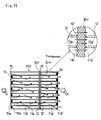
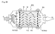
- a cylindrical wall flow type staggered seal DPF 10X is supported by a DPF holding mat 32 and fixed to a cylinder case 31 for introducing an exhaust gas G into all of the cells 11a, 11b from the total upstream surface of the DPF 10X.
- the exhaust gas purification system 20X is devised to introduce the exhaust gas G evenly into all of the cells 11a, 11b of the DPF 10X by diffusing the exhaust gas G, however, the exhaust gas flow rate tends to increase in the central portion of the DPF 10X and, also, the outer peripheral side of the DPF 10X tends to be cooled down by heat radiation, decreasing the temperature towards the downstream, and thus lowering the temperature by heat radiation. Consequently, the amount of accumulation increases in the outer peripheral passage portion, and the downstream portion of the central portion of the exhaust gas inflow cross-section of the DPF 10X.
- the DPF temperature exceeds the heat resistance temperature (about 1450 C°) of the cordierite or the like forming the DPF, melting damage is generated locally and partially. If the melding damage is generated, not only the PM collecting ability lowers, but also the portion susceptible to the PM accumulation moves around the melting damage portion, and the temperature of the peripheral portion increased consecutively to expand the melting damage portion, causing a considerable problem for the exhaust gas purification system.
- the thermal stress increases if the DPF temperature distribution is uneven, and the repeat of this thermal stress generates the fatigue destruction of the DPF, decreasing its life, or the catalyst endurance temperature being exceeded, the catalyst deteriorates abnormally.
- the exhaust gas flow rate is high in the central portion, the exhaust gas is hot and the PM can burn relatively easily in the exhaust gas while, downstream, the exhaust gas temperature lowers due to heat radiation or others, the PM can be collected easily without burning and accumulated downstream, and the clogging proceeds from the downstream to the upstream.
- the exhaust gas upstream the central portion, the exhaust gas is relatively hot and the PM can burn easily as oxygen for its combustion is supplied abundantly. Consequently, if the PM burns upstream, the heat generated by its combustion heats the exhaust gas moving downstream and, at the same time, the heat propagated from members of the DPF heats the downstream portion of the DPF, increasing the temperature of the DPF in its downstream portion.
- the temperature elevation promotes the PM combustion, increasing the temperature all the more. This is repeated consecutively towards the downstream, the temperature of DPF and exhaust gas temperature increases towards the downstream in the central portion, increasing the downstream temperature in particular.
- the present invention has an object to provide an exhaust gas purification system of excellent endurance capable of avoiding DPF melting damage or breakage, by equalizing the heat distribution of the diesel particulate filter (DPF) and preventing an abnormally high temperature from generating partially.
- DPF diesel particulate filter
- the structure of portions where particulate matter (the PM) accumulates easily and the temperature raises is partially modified, strong and weak catalyst oxidation power is used, the disposition of the exhaust gas communication passage is devised, and so on.
- exhaust gas passage prevention structure heat absorber, and heat diffusion portion of high heat conductivity are disposed in the portions of the DPF where the PM accumulates easily and the temperature raises easily.
- the catalyst oxidation power to be disposed in the DPF is composed so as to decrease in order, step-wise or continuously, from the upstream to the downstream of the DPF, or, from the outer periphery towards the center of the DPF.
- the exhaust gas temperature is raised by accelerating the oxidation of NO or other components in the exhaust gas by a strong oxidizing catalyst, in the outer peripheral passage where the exhaust gas cools downs by heat radiation and, at the same time, the exhaust gas temperature elevation is limited by controlling the oxidation of NO or other components in the exhaust gas by a weak oxidizing catalyst, in the central passage where exhaust gas tends to become hot.
- the DPF is heated or kept warm by the exhaust gas, by circulating the total amount of exhaust gas through the outer periphery and the central portion of the DPF, and the DPF is kept hot by the heat-retention effect, to promote the PM combustion.
- composition is as follows.
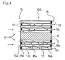
- the wall flow type DPF used for the exhaust gas purification system of the first and the second embodiments, as shown in FIG 1 to FIG 4, has a number of exhaust gas passages 11a, 11b whose periphery is formed of porous wall surface 12 and, at the same time, is formed by stop sealing in zigzag 13 an inlet side 15 and an outlet side 16 of the exhaust gas passages (cells) 11 a, 11 b, and is used by incorporating in an exhaust gas purification systems 1A, 1B, 1C or others as shown in FIG. 32 to FIG. 34.
- it is composed by installing an exhaust gas passage prevention structure, against the exhaust gas passages 11a, 11b in the central portion of the exhaust gas inflow portion of the DPF 10A, 10B.
- the exhaust gas passage prevention structure is installed, against thirteen exhaust gas passages 11 a, 11b in the central portion.
- the exhaust gas passage prevention structure is composed by stop sealing 13A both the upstream side and the downstream side of the cell 11a, 11b of the central portion C of the DPF 10A, so that the exhaust gas G cannot enter in the cells 11 a, 11b of the central portion C thereof.
- the obstruction of the passage of the exhaust gas G makes the exhaust gas G flowing toward the central portion C is directed around the central portion C of the stop seal 13A, the whole exhaust gas G can be filtered by making it pass through a wall face 12 having the filtering function of the DPF 10A.
- an exhaust gas passage prevention structure is installed by forming the central portion C of the DPF 10B with a solid structure 17, and composing so that the exhaust gas passage be absent in the central portion C.
- the formation of the solid structure 17 increases the heat capacity, allowing to absorb and accumulate by the solid portion C heat generated through combustion of PM accumulated around the central portion C and also to diffuse by heat conduction, hence, a local high temperature around the central portion C is prevented.
- the solid portion 17 has heat accumulating function and heat conducting function, and acts in a temporal and spatial homogenization direction of the DPF temperature, by conducting accumulated heat to the upstream side and the surrounding wall face, thus allowing to promote the combustion of PM in the exhaust gas G and collected PM.
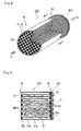
- the DPF for the exhaust gas purification system of third to fifth embodiments shown in FIG. 5 to FIG. 7 is composed by installing a heat absorbers 17C, 17D, 17E in the central portion C of the exhaust gas inflow portion and in the surrounding portion of the central portion C, of the DPFs 10C, 10D, 10E.
- a heat absorber 17C formed by increasing the wall thickness of the porous wall face 12 is provided in a well curb shape, surrounding the central portion C of the exhaust gas inflow face of the DPF 10C, namely portion where the temperature tends to raised, when the oxidation of accumulated particulate matter has started, during the regeneration mode operation or others.
- the temperature of the DPF 10C is directed to a temporal and spatial homogenization direction, allowing to promote the combustion of particulate matter in the exhaust gas and the combustion of collected particulate matter during the normal operation. Consequently, the amount of accumulation of particulate matter decreased, the regeneration mode operation interval becomes longer, allowing to improved the durability and the life.
- a heat absorber 17D is provided cylindrically surrounding the central portion C of the DPF 10D.
- the heat absorber 17D is made of the same material as the porous wall face 12 and formed similarly, but heat accumulating function and heat conducting function are improved compared to the porous wall face 12, by increasing the wall face thickness.
- a heat absorber 17E is provided crossing at the central portion C of the DPF 10E.
- the heat absorber 17E is made of the same material as the porous wall face 12 and formed similarly, but heat accumulating function and heat conducting function thereof are improved compared to the porous wall face 12, by increasing the wall thickness.
- the heat generated through combustion of PM accumulated around the central portion C cab be absorbed and accumulated by the heat absorber 17E and diffused by the heat transmission, thereby preventing the surrounding of the central portion C from heating locally.
- the heat absorber 17E has heat accumulating function and heat conducting function, and acts in a temporal and spatial homogenization direction of the DPF temperature, by conducting accumulated heat to the upstream side and the surrounding porous wall face, thus allowing to promote the combustion of PM in the exhaust gas G and collected PM.
- the heat absorber 17C, 17D, 17E is made of the same material as the porous wall face 12; however, it may also made of other material, for instance, stainless steel of metal material or ceramic material. In addition, concerning the shape, it may be molded integrally, or may be formed separately and then integrated by assembly.
- heat absorber 17C, 17D, 17E is not limited to well curb, lattice, concentric, ring or radical form, but it may also be disposed in another form or in a combined form.
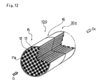
- the DPF of the exhaust gas purification system of the sixth to eighth embodiment shown in FIG. 8 to FIG. 16 is composed by providing a heat diffusion member 30F to 30L, against the downstream side of the DPF 10F, 10G.
- the heat diffusing member to be used for the exhaust gas purification system of the sixth embodiment is an aeration member 30F such as aerating heat resistant metal mesh or porous flat plate using alloy of aluminum, aluminum titanate or other metals, silicone carbide, alumina or others ceramics as material, abutted to the face of the downstream side 16 of the DPF 10F. It may bonded by an adhesive, but it may also be disposed so as to come into contact. Namely, it is so disposed to improve the efficiency of heat conduction.
- the heat diffusion member 30F may be a single plate, but a plurality of members may also be laminated. Especially, in the case of metal mesh, it is laminated preferably in order to secure an appropriate heat conduction characteristic and heat capacity.
- the difference of heat expansion between the DPF 10F and the heat diffusion member 30F can be absorbed by the friction between planes each other.
- thermoelectric heat distribution As the heat can be diffused in a direction to uniform the DPF heat distribution, especially radial heat distribution, and, particulate matter (PM) collection speed and combustion speed, a temperature distribution as shown in FIG. 17 can be obtained.
- PM particulate matter
- the heat diffusing member to be used for the seventh embodiment is composed of a stop sealing plate 30G having a stop sealing protrusion 13B disposed in zigzag, using alloy of aluminum, aluminum titanate or other metals, silicone carbide, alumina or others ceramics as material.
- the stop sealing plate 30G is inserted and bonded from the downstream side 16 of the DPF 10G, and the outlet portion 16b of the downstream side 16 of the DPF 10G is sealed in zigzag with the stop sealing protrusion 13G.
- the bonding is realized by an adhesive 40, for absorbing the generation of gap due to the difference of heat expansion between the DPF 10G and the stop sealing plate 30G.
- the heat can be diffused in a direction to uniform the DPF heat distribution, especially radial heat distribution, and, particulate matter (PM) collection speed and combustion speed, by the stop sealing plate 30G.
- the heat diffusing member to be used for the eighth embodiment is composed by connection a wall flow type second DPF 30H, 30I, 30J formed by using aluminum alloy, aluminum titanate or other metals, silicone carbide, alumina or others ceramics as material, to the downstream side of a wall flow type first DPF 1 OF, 10G composed of cordierite.
- the downstream side 16 of the first DPF 10G is not stop sealed
- the second DPF 30H is composed of a mesh of cell same as the first DPF 10G
- the upstream side is not stop sealed
- the position of the downstream side well curb-like stop seal 13' is differentiated from the position of the upstream side stop seal 13 of the first DPF 10G. Namely, it is so composed that the upstream side cell 11 a of the first DPF 10G and the upstream side cell 11 a' of the second DPF 30H are connected.
- a first DPF 10F wherein an upstream side 15 and a downstream side 16 are stop sealed respectively, and a second DPF 30I wherein an upstream side and a downstream side are also stop sealed are bonded with an adhesive 40.
- the second DPF 30I is composed of a mesh of cell same as the first DPF 10G, and formed so that the position of the upstream side well curb-like stop seal 13' will be the same position as the position of the downstream side stop seal 13 of the first DPF 10G. Namely, it is so composed that the downstream side cell 11b of the first DPF 10G and the downstream side cell 11a' of the second DPF 30I are connected.
- FIG. 15 another composition shown in FIG. 15 is substantially same as the composition of FIG. 13, but an aeration member 30F which is a heat diffusion member is disposed between the first DPF 10F and the second DPF 30H. The radial heat conduction is promoted through the aeration member 30F.
- an aeration member 30F which is a heat diffusion member is disposed between the first DPF 10F and the second DPF 30H. The radial heat conduction is promoted through the aeration member 30F.
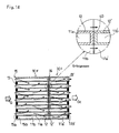
- Still another composition shown in FIG. 16 resembles to the composition in FIG 14, and a stop seal plate 30K wherein stop seal protrusions 13K, 13K' are formed in zigzag on both face sides is bonded by adhesive 40 with the downstream side 16 of the first DPF 10F and the upstream side of the second DPF 30J. There, the radial heat conduction is promoted through the stop seal plate 30K.
- the boding by means of the adhesive 40 absorbs the difference of heat conductivity between the first DPFs 10F, 10G and the second DPFs 30H, 30I, 30J, or the aeration member 30F, the stop seal plate 30K.
- the upstream side first DPF 10F, 10G being composed of cordierite or other material showing a low heat conductivity, an excellent heat retention, and, a low heat capacity and an excellent heat elevation, become hot relatively rapidly, allowing to promote the combustion of PM.
- the downstream side second DPFs 30H, 30I, 30J being composed of silicone carbide, alumina or other ceramic material presenting a high heat conductivity, an excellent diffusivity, and, a large heat capacity and a mediocre heat elevation, allows to diffuse and accumulate heat, in order to avoid an abnormally high temperature.
- an aeration member 30F or stop seal palte 30K which is a heat diffusion member between the first DPFs 10F, 10G and the second DPFs 30H, 30J, can promote the radial heat conduction.
- the wall flow type filter 10L. 10M, 10N has a number of exhaust gas passages (cells) 11 a, 11b whose periphery is formed of porous wall surface 12 and is formed by stop sealing in zigzag 13 the inlet side 15 and the outlet side 16 of the exhaust gas passage s11a, 11b.
- a catalyst 30a to 30d made of oxidation catalyst, or, oxidation catalyst and PM oxidation catalyst is applied to the wall surface of the exhaust gas passage 11a, 11b.
- the oxidation catalyst is formed with a rear metal such as platinum, and is a catalyst for oxidizing nitrogen monoxide (NO) into nitrogen monoxide (NO 2 ) with oxygen (O 2 ) in the exhaust gas, and oxidizes PM with the generated NO 2 .
- the PM oxidation catalyst formed of cerium dioxide or the like is a catalyst for directly oxidizing the PM by activating the oxide in the exhaust gas.
- the exhaust gas G enters the exhaust gas passage 11 a from the inlet side 15, passes through the porous wall face 12, enters the exhaust gas passage 11b, and discharged from the outlet side 16 as purified exhaust gas Gc.
- PM in the exhaust gas when it is hot, is purified through oxidation and combustion by the catalytic effect of the catalyst 30a to 30d applied to the porous wall surface 12.
- the collected PM is eliminated through oxidation and combustion by the catalytic effect of the catalyst 30a to 30d during the regeneration control operation.
- the oxidation power of the catalysts 30a, 30b to be disposed in the DPF 10L is composed so as to decrease in order and step-wise from the upstream to the downstream of the DPF 10L.
- the DPF 10L is divided into an upstream side zone ZA1, an central portion zone ZA2 and a downstream side zone ZA3, from upstream to downstream, a strong oxidation power catalyst 30a is disposed by coating in the upstream side zone ZA1, a weak oxidation power catalyst 30b in the central portion zone ZA2 respectively, while the downstream side zone (downstream end portion) ZA3 is not coated with catalyst, so as to decrease the oxidation power in three stages.
- the change of oxidation power of the catalyst 30a, 30b can be realized by changing the kind of catalyst, or even when the same catalyst is used, by changing the support concentration during the coating.
- the oxidation power of the catalysts 30a, 30b to be disposed in the DPF 10M is composed so as to decrease in order and step-wise, from the outer periphery towards the center of the DPF 10M.
- the DPF 10M is divided into a cylindrical outer peripheral side zone ZB1, an intermediate tubular zone ZB2 and a central side zone ZB3, from the outer peripheral side to the central side, a strong oxidation power catalyst 30a is disposed by coating in the cylindrical outer peripheral side zone ZB1, a weak oxidation power catalyst 30b in the intermediate tubular zone ZB2 respectively, while the central side zone (center portion) ZB3 is not coated with catalyst, so as to decrease the oxidation power in three stages.
- the oxidation power of the catalysts 30a-30d to be disposed in the DPF 10N is composed so as to decrease in order and step-wise from the outer peripheral portion B of the upstream end to the central portion C of the downstream end of the DPF 10N.
- the DPF 10N is divided into several zones ZC1 to ZC5 by division lines approximating a parabola which is convex at the upstream side, from the outer peripheral portion B of the upstream end to the central portion C of the downstream end, and strong oxidation power catalysts 30a to 30d are disposed by coating consecutively, from the zone ZC1 near the outer peripheral portion of the upstream end.
- the zone ZC5 of the central portion of the downstream end is not coated with catalyst, so as to decrease the oxidation power in multiple stages (5 stages).
- the DPF10L, 10M, 10N is used by incorporating in the exhaust gas purification system 1B, 1C or the like as shown in FIG. 33 or FIG. 34, according to the kinds of catalyst 30a to 30d.
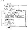
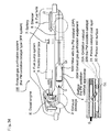
- the DPF regeneration control is performed according to a regeneration control flow as shown in FIG. 25.
- the regeneration control flow is shown as a control flow to be executed in parallel with a main control flow for controlling the engine, or others. Consequently, when the engine operation is started, the flow is called from the main control flow to start, and the execution thereof is stopped, by interruption, at the same time at the engine operation stop command such as stopping the engine or others, it returns and goes back to the main control flow. It should be noted that the execution suspension portion by the interruption is not illustrated in the regeneration control flow of FIG. 25.
- the normal operation is performed for a predetermined period of time in the step S11, before going to the step S12, it is judged if the filter requires the regeneration control or not, and if unnecessary, it returns to the normal operation of the step S11.
- step S12 If it is judged that the filter regeneration control is required by the judgment in the step S12, it proceeds to the step S20 to perform the regeneration control operation.
- the downstream exhaust gas temperature Tc of the DPF is monitored to judge if it is lower than the set temperature Tc0 which would provoke DPF melting damage or destruction, and catalyst deterioration.
- the exhaust gas heat-up control for filter regeneration is performed for a certain period of time and, in the judgment of the step S21, in case where the downstream exhaust gas temperature Tc of the DPF is lower than the set temperature Tc0, the exhaust gas heat-up control is set in the step S22 and it proceeds to the step S24, while in case where the exhaust gas temperature Tc exceeds the set temperature Tc0, the exhaust gas heat-up suspension is set in the step S23 and it proceeds to the step S24.
- the regeneration control operation is performed for a certain period of time in the step S24 according to the setting of the step S22 or step S23, it is to terminate or not the regeneration control operation and, if to terminate, it returns to the normal operation of the step S11 and if not to terminate, it returns to the step S21, to continue the regeneration control operation.
- portions where catalysts 30b to 30d of low oxidation power are disposed potion portion ZA2 of the downstream side (after-flow side), intermediate tubular zone ZB2, central portion side portions ZC2 to ZC4 of the downstream side) through heat conduction or others from the heated up exhaust gas, the upstream side or the outer peripheral side, even the catalysts 30b to 30d of low oxidation power and weak oxidation activate sufficiently, and the oxidation of PM is performed.
- an exhaust gas purification system 120A in the case of application to a continuous regeneration type DPF system 1 U of NO 2 regeneration type DPF system shown in FIG. 32 shall be described.
- the exhaust gas purification system 120A shown in the FIG. 22 is a purifier using oxidation of particulate matter (PM) by NO 2 , comprising an upstream oxidation catalyst converter 3Aa and a downstream wall flow type DPF 110A, wherein NO in the exhaust gas is oxidized by the upstream oxidation catalyst converter 3Aa and PM collected by the downstream DPF 110A is oxidized by the generated NO 2 into CO 2, to eliminate PM.
- PM particulate matter
- the oxidation catalyst converter 3Aa is the one supporting an oxidation catalyst 32A (32As, 32Aw) in the exhaust gas passage of a honeycomb structure made of cordierite or ceramics, formed in a tubular shape where the exhaust gas G enters the upstream end portion and exits from the downstream end portion.
- an outer peripheral side passage portion Z1 (hatched portion) of the oxidation catalyst converter 3Aa supports a strong oxidation catalyst 32As made of rear metal system oxidation catalyst or the like, while a central side passage portion Z2 (non hatched portion) supports a weak oxidation catalyst 32Aw made of oxide system oxidation catalyst or the like.
- the cross-section area of the outer peripheral side passage portion Z1 supporting the strong oxidation catalyst 32As is set to 0.5 to 1.0 times of the cross-section area of the central side passage portion Z2 supporting the weak oxidation catalyst 32Aw in order to keep a good temperature distribution formation in the downstream side DPF 110 A, oxidation efficiency by the catalyst effect, thermal retention countermeasures or others in a good state.
- the DPF 110A is also formed in a tubular shape where the exhaust gas G enters the upstream end portion and exits from the downstream end portion.
- the DPF 110A is made of a wall flow type filter 10X or others as shown in FIG. 35.
- the wall flow type filter 10X made of cordierite or ceramics, comprises a number of exhaust gas passages (cell) whose periphery is formed of porous wall surface 12 and an inlet side 15b and an outlet side 16b of the exhaust gas passage 11 a, 11b stop sealed in zigzag.
- the exhaust gas purification system 120A of the composition in the normal operation mode, as the outer peripheral side passage portion Z1 where the exhaust gas temperature tends to lower easily by heat radiation or others supports the strong oxidation catalyst, in the upstream side oxidation catalyst converter 3Aa, and therefore, the oxidation effect is enhanced, the oxidation reaction of PM or NO components or others contained in the exhaust gas is promoted, resulting in the elevation of the exhaust gas temperature.
- the global temperature distribution of the oxidation catalyst converter 3Aa and the downstream side DPF 110A is equalized, in a way to enlarge the combustion area of PM in the exhaust gas, in the normal engine operation.
- the temperature distribution in the DPF 110A is made uniform wholly and the abnormal high temperature parts is not caused during the regeneration mode operation, so the melting of the filter can be avoided.
- an exhaust gas purification system 120B in the case of application to a continuous regeneration type DPF system 1V of NO 2 regeneration type DPF system shown in FIG. 33 shall be described.
- the exhaust gas purification system 120B shown in the FIG. 24 is a purifier wherein oxidation catalyst 32A (32As, 32Aw) is applied to the wall surface of the wall flow type filter with catalyst 110B to achieve oxidation of NO in the exhaust gas and PM oxidation by NO 2 generated by the oxidation, on the wall surface.
- oxidation catalyst 32A 32As, 32Aw
- a strong oxidation catalyst 32As made of rear metal system oxidation catalyst or the like and a weak oxidation catalyst 32Aw made of oxide system oxidation catalyst or the like are prepared, and as shown in FIG. 24, an outer peripheral side passage portion Z1 of the DPF 110B supports the strong oxidation catalyst 32As, while a central side passage portion Z2 supports the weak oxidation catalyst 32Aw respectively.
- the cross-section area of the outer peripheral side passage portion Z1 supporting the strong oxidation catalyst 32As is set to 0.5 to 1.0 times of the cross-section area of the central side passage portion Z2 supporting the weak oxidation catalyst 32Aw in order to keep a good temperature distribution formation in the DPF 110 B, oxidation efficiency by the catalyst effect, or others in a good state.
- the exhaust gas purification system 120B of the composition in the normal operation mode, as the outer peripheral side passage portion Z1 supports the strong oxidation catalyst 32As, the oxidation reaction of components such as NO or others contained in the exhaust gas in the DPF 110B is promoted, resulting in the elevation of the exhaust gas temperature, while in the central side passage portion Z2 supporting the weak oxidation catalyst 32Aw, the oxidation reaction and the elevation exhaust gas temperature are reduced, and consequently, the global temperature distribution of the DPF 110B is equalized,.
- the oxidation reaction of PM collected by DPF 110B is promoted in the outer peripheral side passage portion Z1 supporting the strong oxidation catalyst 32As and raises the filter temperature, while the oxidation reaction of collected PM is slow in the central side passage portion Z2 supporting the weak oxidation catalyst 32Aw, and consequently, the global temperature distribution of the DPF 110B is equalized.
- the filter melting damage due to an abnormally high temperature combustion that can happen easily during the regeneration operation can be prevented.
- an exhaust gas purification system 120C in the case of application to a continuous regeneration type DPF system 1W of NO 2 regeneration type DPF system shown in FIG. 34 shall be described.
- the exhaust gas purification system 120C shown in the FIG. 25 is a purifier wherein oxidation catalyst 32A (32As, 32Aw) and PM oxidation catalyst 32B are applied to the wall surface of the wall flow type filter with PM oxidation catalyst 110C to achieve oxidation of PM from a temperature lower than the wall surface.
- the PM oxidation catalyst 32B is a catalyst for oxidizing PM directly with O 2 in the exhaust gas and is made of cerium dioxide or others.
- PM is oxidized with NO 2 using a reaction to oxidize NO of the oxidation catalyst 32A into NO 2 , mainly, in the low temperature oxidation area (about 350 C° to 450 C°), PM is oxidized using a reaction to oxidize PM directly with O 2 in the exhaust gas O 2 of the PM oxidation catalyst 32B in the middle temperature oxidation area (about 400 C° to 600 C°), while PM is oxidized with O 2 in the exhaust gas, in the high temperature oxidation area (equal or superior to about 600 C°) higher than the temperature at which PM burns with O 2 in the exhaust gas.
- the oxidation catalyst 32A is composed so that a strong oxidation catalyst 32As made of rear metal system oxidation catalyst or the like and a weak oxidation catalyst 32Aw made of oxide system oxidation catalyst or the like are prepared, and an outer peripheral side passage portion Z1 of the DPF 110 C supports the strong oxidation catalyst 32As and the PM oxidation catalyst 32B, while a central side passage portion Z2 supports the weak oxidation catalyst 32Aw and the PM oxidation catalyst 32B respectively.
- the cross-section area of the outer peripheral side passage portion Z1 supporting the strong oxidation catalyst 32As is set to 0.5 to 1.0 times of the cross-section area of the central side passage portion Z2 supporting the weak oxidation catalyst 32Aw in order to keep a good temperature distribution formation in the filter, oxidation efficiency by the catalyst effect or others in a good state.
- the temperature distribution of the DPF 110C can be equalized, and as a result, the filter melting damage can be avoided by preventing an abnormally high temperature from generating.
- DPFs 210A to 210F used for the exhaust gas purification system 20A to 20F is composed of a wall flow type filter having a number of exhaust gas passages 11a, 11b whose periphery is formed of porous wall surface 12 and an inlet side 15b and an outlet side 16b of cells 11a, 11b constituting the exhaust gas passage stop sealed in zigzag 13, to be used incorporated in an exhaust gas purification system 1U, 1V, 1W or others as shown in FIG. 32 to FIG. 34. Consequently, the DPF 210A to 210F may be a normal DPF, or a DPF with a catalyst such as oxidation catalyst, namely catalytic DPF.
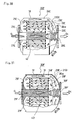
- a DPF 210A made of a wall flow type filter is formed into a tubular body such as cylindrical form or the like and an outer peripheral passage 24A is disposed at the outer peripheral portion of the tubular body and a central passage 27A in the central portion along the central axis respectively.
- an outside chamber 25A communicating the outer peripheral passage 24A and the upstream side cell 11a is installed, and moreover, an inside chamber 26A communicating the downstream side cell 11b and the central passage 27A is provided.
- a gas inlet passage 23A is provided outside the inside chamber 26A, to communicate the gas inlet 21A and the outer peripheral passage 24A.
- a gas diffusion member 22A is disposed at the gas inlet 21A, and composed to diffuse equally the inflow exhaust gas G in the outer peripheral passage 24A.
- an ash discharge port 34 is disposed in the downstream portion of the outside chamber 25A in order to discharge ash accumulated in the outside chamber 25A.
- the exhaust gas passage is composed so that the exhaust gas G passes through the gas inlet 21A, gas diffusion member 22a, gas inlet passage 23A, outer peripheral passage 24A, outside chamber 25A, cell 11a, 11b, inside chamber 26A, central passage 27A, and gas outlet passage 28A in the order.
- the outer peripheral side of the DPF 210A can be heated or kept warm by the exhaust gas G, by flowing the total amount of exhaust gas G through the outer peripheral passage 24A and then through the cells 11a, 11b of the DPF 210A, contributing to a further homogenization of the temperature distribution of the DPF 210A both in the engine normal mode operation and the DPF regeneration mode operation.
- the outer peripheral passage 24A is formed as a passage between the outer periphery of the DPF 210A and a case 31 of the exhaust gas purification system 20A, as a passage provided outside the DPF 210A.
- the outer peripheral side of the DPF 210A is fixedly supported by an inner wall 26a continuous to an inner chamber 26A through a DPF holding mat 32.
- the filter portion more vulnerable than the other portions can be protected, and the expensive filter portion will not be damaged during transportation or installation of the exhaust gas purification system 20A, even if the outside or the exhaust gas purification system 20A is damaged.
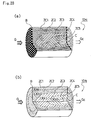
- the outer peripheral passage 24B can be formed by removing stop seals before and after several layers of cells 11a', 11b' in an inside area along the outer periphery of the tubular body of the DPF 210B.
- the composition of removing the stop seal 13 can be formed relatively easily, because it can be molded into a shape from which the stop seal 13 is taken out during the molding of the DPF 210B. In the case, the outer peripheral side of the DPF 210B comes to be held through the DPF holding mat 32.
- an oxidation catalyst is disposed in the outer peripheral passage 24B.
- the composition permits to heat the outer peripheral side of the DPF 210B with oxidation reaction heat by the oxidation catalyst. Also, the space for disposing the oxidation catalyst can be economized.
- oxidation catalyst on the outer peripheral passage 24B, it may be supported by the porous wall face 12 around the cell 11a', 11b' from which the stop seal 13 is taken out as shown in FIG. 27, or a porous support layer supporting the oxidation catalyst may be laminated on the porous wall face 12.
- the outer peripheral passage 24C is formed as a passage between the outer periphery of the DPF 210C and a case 31 of the exhaust gas purification system 20C, and in the passage 24C, the oxidation catalyst is supported by a ceramic or metal honeycomb structure 41 formed separately from the DPF 210C, and the honeycomb structure 41 is disposed through insertion into the outer peripheral passage 24C.
- the oxidation support step can be cut off from the molding step of the DPF 210C and, moreover, the oxidation catalyst can be disposed relatively easily in the outer peripheral passage 24C.
- central passages 27A, 27B, 27C as shown in FIG. 26 and FIG. 27, an area along the central axis of a tubular body is formed hollow, and the hollow portion is taken as the central passage 27A, 27B, or as shown in FIG. 28, the central passage 27C is formed by removing stop seals before and after cells 11 a", 11b" in an area along the central axis of the tubular body.
- central passages 27A, 27B, 27C are formed in a portion including the downstream side of the central portion where an extremely high temperate generates to create the DPF melting damage, in a DPF 10X of the prior art of FIG. 35, the melting damage which was encountered in the DPF 10X of the prior art can be avoided.
- compositions in FIG. 26 to FIG. 28 are nothing but exemplary, and the present invention is not limited to the combinations shown in these drawings.
- relief valves 33A, 33B, 33C are disposed so that the exhaust gas G bypasses the DPFs 210A, 210B, 210C, when the clogging of the DPFs 210A, 210B, 210C progresses and increases the pressure.
- the relief valves 33A, 33B, 33C are disposed, as shown in FIG. 26, on a passage wall 28w between an outside chamber 25A communicating the outer peripheral passage 24A and the upstream side cell 11a, and the gas outlet passage 28A, or, as shown in FIG. 27, on a passage wall 26w between an inside chamber 26B communicating the downstream side cell 11b and the central passage 27B and the gas inlet passage 23B. Otherwise, as shown in FIG. 28, it may be disposed in a portion inside the gas diffusion member 22C of the passage wall 26w between an inside chamber 26C communicating the downstream side cell 11b and the central passage 27C, and the gas inlet passage 23C.
- the disposition of the relief valves 33A, 33B, 33C allows to avoid an excessive elevation of the engine exhaust pressure, by bypassing the filtration portion, when the DPFs 210A, 210B, 210C are clogged excessively by an abnormal accumulation of particulate matter.
- the piping for arranging the relief valves 33A, 33B, 33C becomes unnecessary, making the exhaust gas purification system more compact.
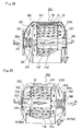
- a wall flow type DPF 210D is formed into a tubular body such as cylindrical form or the like and an outer peripheral passage 24D is disposed at the outer peripheral portion of the tubular body and a central passage 27D in the central portion along the central axis respectively.
- an inside chamber 26D communicating the central passage 27D and the upstream side cell 11a is provided, and an outside chamber 25D communicating the downstream side cell 11b and the outer peripheral passage 24D is installed.
- a gas outlet passage 23D is provided outside the inside chamber 26D, to communicate the gas outlet 28D and the outer peripheral passage 24D.
- composition of the sixteenth embodiment is different from the composition of the fifteenth composition in that the exhaust gas G passes through the central passage 27D before the cells 11a, 11b, and then through the outer peripheral passage 24D, and, the portion where oxidation catalyst is disposed in the central passage 27D.
- the outer peripheral passage 24D is disposed outside the DPF 210D as a passage between the outer periphery of the DPF 210D and the case 31; however, the outer peripheral passage may also be formed be removing stop seals before and after the cell in the area along the outer periphery of the tubular body of the DPF, as is the case for the composition of FIG. 27.
- an area along the central axis of a tubular body may be formed hollow, and the hollow portion may be taken as central passage 27D, or though not shown, it can be formed by removing stop seals before and after cells in an area along the central axis of the tubular body.
- an oxidation catalyst is disposed in the central passage 27E.
- the oxidation catalyst is supported by a ceramic or metal honeycomb structure 42 formed separately from the DPF 210E, and the honeycomb 42 is disposed through insertion into the central passage 27E of the DPF 210E.
- the honeycomb 43 is disposed in connection with the member composing the gas inlet 21 F, and composed to be inserted into the central passage 27F of the DPF 210F during the assembly of the exhaust gas purification system 20F.
- the central passage may be formed by removing stop seals before and after cells in an area along the central axis of the tubular body, and the oxidation catalyst can be arranged in the central passage, by providing on the porous wall surface around the cell along the central axis of the tubular body, or, by laminating a porous support layer supporting oxidation catalyst on the porous wall surface.
- disposition of a thermal insulation layer 51 on the outer surface of the case 31 of the DPF 20F can enhance the thermal retention effect and, at the same time, prevent thermal damage of peripheral vehicle components disposed outside by the heat.
- the thermal insulation layer 51 having also a normal noise reduction effect can serve for prevention of noise.
- the central portion of the DPF 210E can be heated with heat of the exhaust gas G and heat generated by oxidation reaction of substances in the exhaust gas G.
- a relief valve is disposed, so that the exhaust gas G bypasses the DPFs 210D, 210E, 210F, when the clogging of the DPFs 210D, 210E, 210F progress and increases the pressure.
- the relief valves 33D, 33E, 33F are disposed, as shown in FIG. 29, on a passage wall 21w between an outside chamber 25D communicating the outer peripheral passage 24D and the downstream side cell 11b, and the gas inlet passage 21 D, or, as shown in FIG. 30, on a passage wall 26w between an inside chamber 26E communicating the upstream side cell 11 a and the central passage 27E, and the gas outlet passage 23E. Otherwise, as shown in FIG. 31, it may be disposed in a central portion of the passage wall 26w between an inside chamber 26F communicating the upstream side cell 11a and the central passage 27C, and the gas outlet passage 23F.
- the disposition of the relief valves 33D, 33E, 33F allows to avoid an excessive elevation of the engine exhaust pressure, by bypassing the filtration portion, when the DPF s210D, 210E, 210F are clogged excessively by an abnormal accumulation of particulate matter.
Landscapes
- Engineering & Computer Science (AREA)
- Chemical & Material Sciences (AREA)
- Physics & Mathematics (AREA)
- Geometry (AREA)
- Chemical Kinetics & Catalysis (AREA)
- Combustion & Propulsion (AREA)
- Mechanical Engineering (AREA)
- General Engineering & Computer Science (AREA)
- Thermal Sciences (AREA)
- Materials Engineering (AREA)
- Organic Chemistry (AREA)
- Processes For Solid Components From Exhaust (AREA)
- Exhaust Gas After Treatment (AREA)
Applications Claiming Priority (12)
| Application Number | Priority Date | Filing Date | Title |
|---|---|---|---|
| JP2001351231A JP2003148141A (ja) | 2001-11-16 | 2001-11-16 | 排気ガス浄化装置 |
| JP2001351231 | 2001-11-16 | ||
| JP2001351235 | 2001-11-16 | ||
| JP2001351235A JP3951678B2 (ja) | 2001-11-16 | 2001-11-16 | 排気ガス浄化装置 |
| JP2001356222 | 2001-11-21 | ||
| JP2001356208 | 2001-11-21 | ||
| JP2001356208A JP2003155909A (ja) | 2001-11-21 | 2001-11-21 | ディーゼルパティキュレートフィルタ装置用フィルタ |
| JP2001356222A JP3826773B2 (ja) | 2001-11-21 | 2001-11-21 | ディーゼルパティキュレートフィルタ |
| JP2001356231 | 2001-11-21 | ||
| JP2001356231A JP2003155922A (ja) | 2001-11-21 | 2001-11-21 | ディーゼルパティキュレートフィルタ装置用フィルタ |
| JP2001362822A JP2003161138A (ja) | 2001-11-28 | 2001-11-28 | ディーゼルパティキュレートフィルタ |
| JP2001362822 | 2001-11-28 |
Publications (2)
| Publication Number | Publication Date |
|---|---|
| EP1312776A2 true EP1312776A2 (fr) | 2003-05-21 |
| EP1312776A3 EP1312776A3 (fr) | 2004-05-12 |
Family
ID=27555019
Family Applications (1)
| Application Number | Title | Priority Date | Filing Date |
|---|---|---|---|
| EP02025431A Withdrawn EP1312776A3 (fr) | 2001-11-16 | 2002-11-15 | Système pour la purification de gaz d'échappement |
Country Status (2)
| Country | Link |
|---|---|
| US (1) | US20030097834A1 (fr) |
| EP (1) | EP1312776A3 (fr) |
Cited By (22)
| Publication number | Priority date | Publication date | Assignee | Title |
|---|---|---|---|---|
| WO2004070178A1 (fr) * | 2003-01-07 | 2004-08-19 | Peugeot Citroen Automobiles Sa | Systeme d'aide a la regeneration d'un filtre a particules pour ligne d'echappement |
| FR2856108A1 (fr) * | 2003-06-16 | 2004-12-17 | Denso Corp | Epurateur de gaz d'echappement pour moteur a combustion interne avec filtre a particules comportant une zone d'absorption de chaleur |
| EP1536110A1 (fr) * | 2003-11-26 | 2005-06-01 | Delphi Technologies, Inc. | Filtre à particules comportant une couche catalytique pour gaz d'échappement |
| WO2005059324A1 (fr) * | 2003-12-16 | 2005-06-30 | Johnson Matthey Public Limited Company | Systeme d'echappement pour moteur a combustion interne a melange pauvre comprenant un filtre particulaire |
| FR2869072A1 (fr) * | 2004-04-19 | 2005-10-21 | Peugeot Citroen Automobiles Sa | Dispositif de purification de gaz d'echappement |
| EP1598111A1 (fr) * | 2004-05-15 | 2005-11-23 | Delphi Technologies, Inc. | Catalyseur à gradient de concentration susceptible d'être utilisé dans les filtres catalytiques |
| EP1679119A1 (fr) * | 2004-12-24 | 2006-07-12 | Cataler Corporation | Filtre catalyseur pour la purification de gaz d'échappement d'un moteur diesel et son procédé de production |
| EP1693554A1 (fr) * | 2003-11-06 | 2006-08-23 | Hitachi Metals, Ltd. | Filtre en nid d'abeille en ceramique, epurateur de gaz d'echappement et procede d'epuration des gaz d'echappement |
| EP1775010A2 (fr) * | 2005-10-14 | 2007-04-18 | Robert Bosch Gmbh | Canal interne d'un élément de filtration permettant une homogénéisation de la température et filtre pour traitement des rejets gazeux |
| FR2901308A1 (fr) * | 2006-05-18 | 2007-11-23 | Peugeot Citroen Automobiles Sa | Dispositif de traitement de gaz d'echappement d'un moteur thermique de vehicule automobile |
| WO2008052838A1 (fr) * | 2006-11-03 | 2008-05-08 | Robert Bosch Gmbh | Élément de filtrage notamment destiné à filtrer des gaz d'échappement d'un moteur à combustion interne |
| EP2184459A1 (fr) * | 2007-08-31 | 2010-05-12 | Honda Motor Co., Ltd. | Dispositif de purification des gaz d'échappement |
| EP2236783A1 (fr) * | 2009-03-24 | 2010-10-06 | NGK Insulators, Ltd. | Procédé de fabrication d'un dispositif de purification de gaz d'échappement et dispositif de purification de gaz d'échappement |
| EP2261475A1 (fr) * | 2009-06-10 | 2010-12-15 | J. Eberspächer GmbH & Co. KG | Dispositif de purification de gaz d'échappement |
| EP2329118A1 (fr) * | 2008-08-27 | 2011-06-08 | Vida Holdings Corp. Ltd. | Appareil convertisseur catalytique |
| WO2011098855A1 (fr) * | 2009-06-11 | 2011-08-18 | Agco Sa | Module de convertisseur catalytique |
| US8549847B2 (en) | 2008-08-11 | 2013-10-08 | Hitachi Construction Machinery Co., Ltd. | Exhaust gas purifying device |
| CN104196597A (zh) * | 2014-09-09 | 2014-12-10 | 西华大学 | 一种柴油机颗粒捕集器分区电加热再生装置 |
| US9169753B2 (en) | 2003-03-05 | 2015-10-27 | Johnson Matthey Public Limited Company | Diesel engine and a catalysed filter therefor |
| US9260999B2 (en) | 2012-07-19 | 2016-02-16 | Vida Fresh Air Corp. | Apparatus and method for engine backpressure reduction |
| US9964012B2 (en) | 2014-01-17 | 2018-05-08 | Vida Fresh Air Corp. | Method for sizing and positioning catalytic converter insulation |
| DE102018104140A1 (de) * | 2018-02-23 | 2019-08-29 | Volkswagen Aktiengesellschaft | Partikelfilter für einen Verbrennungsmotor sowie Verfahren zur Herstellung eines solchen Partikelfilters |
Families Citing this family (21)
| Publication number | Priority date | Publication date | Assignee | Title |
|---|---|---|---|---|
| JP4279497B2 (ja) * | 2002-02-26 | 2009-06-17 | 日本碍子株式会社 | ハニカムフィルタ |
| US20050056008A1 (en) * | 2003-09-10 | 2005-03-17 | O-Den Corporation | Particulate removing apparatus and diesel engine vehicle equipped with same |
| JP4403944B2 (ja) * | 2004-01-13 | 2010-01-27 | 株式会社デンソー | 内燃機関の排気浄化装置 |
| DE102004008415A1 (de) * | 2004-02-20 | 2005-09-01 | Arvin Technologies, Inc., Troy | Vorrichtung zum Reinigen von Fahrzeugabgasen, insbesondere Dieselrußfilter |
| JP4389606B2 (ja) * | 2004-02-27 | 2009-12-24 | 株式会社デンソー | 内燃機関の排気浄化装置 |
| JP2005344581A (ja) * | 2004-06-02 | 2005-12-15 | Hino Motors Ltd | パティキュレートフィルタ |
| US7621981B2 (en) * | 2006-12-29 | 2009-11-24 | Cummins Filtration Ip, Inc | Apparatus, system, and method for dispersing heat within a particulate filter |
| DE102007010189A1 (de) * | 2007-03-02 | 2008-09-04 | Robert Bosch Gmbh | Verfahren zur Regelung der Regeneration eines Partikelfilters |
| US20080314032A1 (en) * | 2007-05-15 | 2008-12-25 | Xuantian Li | Segmented Particulate Filter For An Engine Exhaust Stream |
| US8240138B2 (en) * | 2007-08-14 | 2012-08-14 | General Electric Company | System and method for reducing particulate matter emission in diesel exhaust gas |
| JP2009154124A (ja) * | 2007-12-27 | 2009-07-16 | Ngk Insulators Ltd | 部分目封止レスdpf |
| CN102046263A (zh) * | 2008-05-29 | 2011-05-04 | 康宁股份有限公司 | 部分壁流式过滤器和方法 |
| US8474249B2 (en) * | 2008-09-08 | 2013-07-02 | Ford Global Technologies, Llc | Optimization of soot distribution in a diesel particulate filter |
| US20100154393A1 (en) * | 2008-12-19 | 2010-06-24 | Ronald Graham Silver | Combination partial flow particulate filter and catalyst |
| US8940242B2 (en) * | 2009-04-17 | 2015-01-27 | Basf Corporation | Multi-zoned catalyst compositions |
| US20110067386A1 (en) * | 2009-09-22 | 2011-03-24 | Gm Global Technology Operations, Inc. | Oxidizing Particulate Filter |
| SE535454C2 (sv) * | 2010-11-16 | 2012-08-14 | Scania Cv Ab | Partikelfilter för ett avgassystem hos en förbränningsmotor |
| KR101261949B1 (ko) * | 2011-05-13 | 2013-05-13 | 현대자동차주식회사 | 촉매유닛 |
| EP2698189B1 (fr) * | 2012-08-17 | 2019-08-07 | Pall Corporation | Module de filtre et système de filtre le comprenant |
| FR3026961B1 (fr) * | 2014-10-10 | 2016-12-09 | Commissariat Energie Atomique | Dispositif de conversion catalytique presentant un temps d'activation reduit |
| US9932873B2 (en) * | 2015-09-18 | 2018-04-03 | Ngk Insulators, Ltd. | Exhaust gas purifying device |
Citations (7)
| Publication number | Priority date | Publication date | Assignee | Title |
|---|---|---|---|---|
| JPH0333419A (ja) * | 1989-06-29 | 1991-02-13 | Mitsubishi Motors Corp | 触媒コンバータ |
| US5089237A (en) * | 1989-07-20 | 1992-02-18 | Daimler-Benz Ag | Gas filter with catalytic coating and a gastight downstream region |
| US5248251A (en) * | 1990-11-26 | 1993-09-28 | Catalytica, Inc. | Graded palladium-containing partial combustion catalyst and a process for using it |
| WO1997024516A1 (fr) * | 1995-12-29 | 1997-07-10 | Sk Corporation | Dispositif eliminant des particules presentes dans les gaz d'echappement de vehicules a moteur diesel |
| JPH10244167A (ja) * | 1997-03-06 | 1998-09-14 | Hino Motors Ltd | 排気ガス浄化用触媒構造体 |
| JP2001263051A (ja) * | 2000-03-17 | 2001-09-26 | Nissan Diesel Motor Co Ltd | ディーゼルエンジンの排気浄化装置 |
| EP1217185A2 (fr) * | 2000-12-20 | 2002-06-26 | Corning Incorporated | Filtres de particules pour moteurs diesel |
Family Cites Families (7)
| Publication number | Priority date | Publication date | Assignee | Title |
|---|---|---|---|---|
| JPS647935A (en) * | 1987-06-30 | 1989-01-11 | Nissan Motor | Catalytic converter device |
| US5055274A (en) * | 1989-02-06 | 1991-10-08 | Tennessee Gas Pipeline Company | Catalytic converter and substrate support with one piece housing |
| US5465573A (en) * | 1992-07-29 | 1995-11-14 | Ngk Insulators, Ltd. | Multi-stage honeycomb heater |
| GB9621215D0 (en) * | 1996-10-11 | 1996-11-27 | Johnson Matthey Plc | Emission control |
| DE19923781C2 (de) * | 1999-05-22 | 2001-04-26 | Degussa | Verfahren und Vorrichtung zur Entfernung von Ruß aus dem Abgas eines Dieselmotors |
| US6669913B1 (en) * | 2000-03-09 | 2003-12-30 | Fleetguard, Inc. | Combination catalytic converter and filter |
| US6912847B2 (en) * | 2001-12-21 | 2005-07-05 | Engelhard Corporation | Diesel engine system comprising a soot filter and low temperature NOx trap |
-
2002
- 2002-11-15 EP EP02025431A patent/EP1312776A3/fr not_active Withdrawn
- 2002-11-18 US US10/295,984 patent/US20030097834A1/en not_active Abandoned
Patent Citations (7)
| Publication number | Priority date | Publication date | Assignee | Title |
|---|---|---|---|---|
| JPH0333419A (ja) * | 1989-06-29 | 1991-02-13 | Mitsubishi Motors Corp | 触媒コンバータ |
| US5089237A (en) * | 1989-07-20 | 1992-02-18 | Daimler-Benz Ag | Gas filter with catalytic coating and a gastight downstream region |
| US5248251A (en) * | 1990-11-26 | 1993-09-28 | Catalytica, Inc. | Graded palladium-containing partial combustion catalyst and a process for using it |
| WO1997024516A1 (fr) * | 1995-12-29 | 1997-07-10 | Sk Corporation | Dispositif eliminant des particules presentes dans les gaz d'echappement de vehicules a moteur diesel |
| JPH10244167A (ja) * | 1997-03-06 | 1998-09-14 | Hino Motors Ltd | 排気ガス浄化用触媒構造体 |
| JP2001263051A (ja) * | 2000-03-17 | 2001-09-26 | Nissan Diesel Motor Co Ltd | ディーゼルエンジンの排気浄化装置 |
| EP1217185A2 (fr) * | 2000-12-20 | 2002-06-26 | Corning Incorporated | Filtres de particules pour moteurs diesel |
Non-Patent Citations (3)
| Title |
|---|
| PATENT ABSTRACTS OF JAPAN vol. 015, no. 168 (M-1107), 26 April 1991 (1991-04-26) & JP 03 033419 A (MITSUBISHI MOTORS CORP), 13 February 1991 (1991-02-13) * |
| PATENT ABSTRACTS OF JAPAN vol. 1998, no. 14, 31 December 1998 (1998-12-31) & JP 10 244167 A (HINO MOTORS LTD), 14 September 1998 (1998-09-14) * |
| PATENT ABSTRACTS OF JAPAN vol. 2000, no. 26, 1 July 2002 (2002-07-01) & JP 2001 263051 A (NISSAN DIESEL MOTOR CO LTD), 26 September 2001 (2001-09-26) * |
Cited By (37)
| Publication number | Priority date | Publication date | Assignee | Title |
|---|---|---|---|---|
| WO2004070178A1 (fr) * | 2003-01-07 | 2004-08-19 | Peugeot Citroen Automobiles Sa | Systeme d'aide a la regeneration d'un filtre a particules pour ligne d'echappement |
| US7328573B2 (en) | 2003-01-07 | 2008-02-12 | Peugeot Citroen Automobiles Sa | Aid system for regeneration of a particle filter for an exhaust line |
| EP1599660B1 (fr) * | 2003-03-05 | 2018-05-23 | Johnson Matthey PLC | Moteur diesel avec un filtre catalysé |
| US9169753B2 (en) | 2003-03-05 | 2015-10-27 | Johnson Matthey Public Limited Company | Diesel engine and a catalysed filter therefor |
| US7159390B2 (en) | 2003-06-16 | 2007-01-09 | Denso Corporation | Exhaust gas cleaner for internal combustion engine with particulate filter having heat-absorbing area |
| FR2856108A1 (fr) * | 2003-06-16 | 2004-12-17 | Denso Corp | Epurateur de gaz d'echappement pour moteur a combustion interne avec filtre a particules comportant une zone d'absorption de chaleur |
| EP1693554A1 (fr) * | 2003-11-06 | 2006-08-23 | Hitachi Metals, Ltd. | Filtre en nid d'abeille en ceramique, epurateur de gaz d'echappement et procede d'epuration des gaz d'echappement |
| EP1693554A4 (fr) * | 2003-11-06 | 2009-09-16 | Hitachi Metals Ltd | Filtre en nid d'abeille en ceramique, epurateur de gaz d'echappement et procede d'epuration des gaz d'echappement |
| EP1536110A1 (fr) * | 2003-11-26 | 2005-06-01 | Delphi Technologies, Inc. | Filtre à particules comportant une couche catalytique pour gaz d'échappement |
| WO2005059324A1 (fr) * | 2003-12-16 | 2005-06-30 | Johnson Matthey Public Limited Company | Systeme d'echappement pour moteur a combustion interne a melange pauvre comprenant un filtre particulaire |
| EP1589199A1 (fr) * | 2004-04-19 | 2005-10-26 | Peugeot Citroen Automobiles S.A. | Dispositif de purification de gaz d'échappement |
| FR2869072A1 (fr) * | 2004-04-19 | 2005-10-21 | Peugeot Citroen Automobiles Sa | Dispositif de purification de gaz d'echappement |
| EP1598111A1 (fr) * | 2004-05-15 | 2005-11-23 | Delphi Technologies, Inc. | Catalyseur à gradient de concentration susceptible d'être utilisé dans les filtres catalytiques |
| EP1859864A1 (fr) | 2004-12-24 | 2007-11-28 | Cataler Corporation | Catalyseur de filtre pour purification de gaz d'échappement d'un moteur diesel et son procédé de production |
| EP1679119A1 (fr) * | 2004-12-24 | 2006-07-12 | Cataler Corporation | Filtre catalyseur pour la purification de gaz d'échappement d'un moteur diesel et son procédé de production |
| EP1775010A3 (fr) * | 2005-10-14 | 2007-10-17 | Robert Bosch Gmbh | Canal interne d'un élément de filtration permettant une homogénéisation de la température et filtre pour traitement des rejets gazeux |
| EP1775010A2 (fr) * | 2005-10-14 | 2007-04-18 | Robert Bosch Gmbh | Canal interne d'un élément de filtration permettant une homogénéisation de la température et filtre pour traitement des rejets gazeux |
| FR2901308A1 (fr) * | 2006-05-18 | 2007-11-23 | Peugeot Citroen Automobiles Sa | Dispositif de traitement de gaz d'echappement d'un moteur thermique de vehicule automobile |
| WO2008052838A1 (fr) * | 2006-11-03 | 2008-05-08 | Robert Bosch Gmbh | Élément de filtrage notamment destiné à filtrer des gaz d'échappement d'un moteur à combustion interne |
| EP2184459A1 (fr) * | 2007-08-31 | 2010-05-12 | Honda Motor Co., Ltd. | Dispositif de purification des gaz d'échappement |
| EP2184459A4 (fr) * | 2007-08-31 | 2010-11-17 | Honda Motor Co Ltd | Dispositif de purification des gaz d'échappement |
| US8549847B2 (en) | 2008-08-11 | 2013-10-08 | Hitachi Construction Machinery Co., Ltd. | Exhaust gas purifying device |
| EP2329118A1 (fr) * | 2008-08-27 | 2011-06-08 | Vida Holdings Corp. Ltd. | Appareil convertisseur catalytique |
| CN105649727B (zh) * | 2008-08-27 | 2018-04-03 | 维达控股股份有限公司 | 用于内燃机的排气系统中的装置 |
| EP2329118A4 (fr) * | 2008-08-27 | 2013-05-29 | Vida Holdings Corp Ltd | Appareil convertisseur catalytique |
| US9926824B2 (en) | 2008-08-27 | 2018-03-27 | Vida Fresh Air Corp. | Catalytic converter apparatus |
| CN105649727A (zh) * | 2008-08-27 | 2016-06-08 | 维达控股股份有限公司 | 用于内燃机的排气系统中的装置 |
| EP2236783A1 (fr) * | 2009-03-24 | 2010-10-06 | NGK Insulators, Ltd. | Procédé de fabrication d'un dispositif de purification de gaz d'échappement et dispositif de purification de gaz d'échappement |
| EP2261475A1 (fr) * | 2009-06-10 | 2010-12-15 | J. Eberspächer GmbH & Co. KG | Dispositif de purification de gaz d'échappement |
| US8568661B2 (en) | 2009-06-10 | 2013-10-29 | Eberspächer Exhaust Technology GmbH & Co. KG | Exhaust gas treatment device |
| WO2011098855A1 (fr) * | 2009-06-11 | 2011-08-18 | Agco Sa | Module de convertisseur catalytique |
| US9260999B2 (en) | 2012-07-19 | 2016-02-16 | Vida Fresh Air Corp. | Apparatus and method for engine backpressure reduction |
| US9964012B2 (en) | 2014-01-17 | 2018-05-08 | Vida Fresh Air Corp. | Method for sizing and positioning catalytic converter insulation |
| CN104196597A (zh) * | 2014-09-09 | 2014-12-10 | 西华大学 | 一种柴油机颗粒捕集器分区电加热再生装置 |
| CN104196597B (zh) * | 2014-09-09 | 2016-07-06 | 西华大学 | 一种柴油机颗粒捕集器分区电加热再生装置 |
| DE102018104140A1 (de) * | 2018-02-23 | 2019-08-29 | Volkswagen Aktiengesellschaft | Partikelfilter für einen Verbrennungsmotor sowie Verfahren zur Herstellung eines solchen Partikelfilters |
| US10918987B2 (en) | 2018-02-23 | 2021-02-16 | Volkswagen Aktiengesellschaft | Particulate filter for an internal combustion engine and method for producing such a particulate filter |
Also Published As
| Publication number | Publication date |
|---|---|
| US20030097834A1 (en) | 2003-05-29 |
| EP1312776A3 (fr) | 2004-05-12 |
Similar Documents
| Publication | Publication Date | Title |
|---|---|---|
| EP1312776A2 (fr) | Système pour la purification de gaz d'échappement | |
| EP1065352B1 (fr) | Pièges à particules pour moteur Diesel | |
| JP3876705B2 (ja) | ディーゼルエンジンの排気ガス浄化システム | |
| CN100443710C (zh) | 柴油发动机及其催化过滤器 | |
| US6802180B2 (en) | Exhaust gas purification system and method for controlling regeneration thereof | |
| JP2005507476A (ja) | 加熱装置を有する開放形の粒子濾過器 | |
| US20070266701A1 (en) | Exhaust particulate filter | |
| JP2000167329A (ja) | 排気ガス浄化装置の再生システム | |
| CN101801499A (zh) | 通过选择性堵塞来调整微粒过滤器性能以及使用多个微粒过滤器来减少排放并提高耐热性 | |
| JP2014520228A (ja) | 自動車用ディーゼルエンジンの運転方法 | |
| US7247185B2 (en) | Device for treatment of a gas flow | |
| JP2008540933A (ja) | 高効率を有する閉塞フリーのフィルタ装置 | |
| US6968681B2 (en) | Method and device for aftertreatment of exhaust gases from combustion engines | |
| JP2003161138A (ja) | ディーゼルパティキュレートフィルタ | |
| JPWO2005045207A1 (ja) | セラミックハニカムフィルタ、排気ガス浄化装置及び排気ガス浄化方法 | |
| JP3826773B2 (ja) | ディーゼルパティキュレートフィルタ | |
| US7716921B2 (en) | Exhaust particulate filter | |
| US20020168304A1 (en) | Devices for managing housing expansion in exhaust emission control devices | |
| JP2003148141A (ja) | 排気ガス浄化装置 | |
| JP3951678B2 (ja) | 排気ガス浄化装置 | |
| JP2008069727A (ja) | 排ガス浄化装置、排ガス浄化触媒用担体基材及び排ガス浄化触媒 | |
| KR100773268B1 (ko) | 디젤 배출가스 정화 장치 및 그 제어방법 | |
| JP2005000818A (ja) | 排気ガス浄化用フィルタ及び排気ガス浄化装置 | |
| JP4407285B2 (ja) | 排気ガス浄化システム | |
| JPH11236813A (ja) | 排気ガス浄化装置の再生システム |
Legal Events
| Date | Code | Title | Description |
|---|---|---|---|
| PUAI | Public reference made under article 153(3) epc to a published international application that has entered the european phase |
Free format text: ORIGINAL CODE: 0009012 |
|
| AK | Designated contracting states |
Designated state(s): AT BE BG CH CY CZ DE DK EE ES FI FR GB GR IE IT LI LU MC NL PT SE SK TR |
|
| AX | Request for extension of the european patent |
Extension state: AL LT LV MK RO SI |
|
| RIC1 | Information provided on ipc code assigned before grant |
Ipc: 7F 01N 3/022 A |
|
| PUAL | Search report despatched |
Free format text: ORIGINAL CODE: 0009013 |
|
| AK | Designated contracting states |
Kind code of ref document: A3 Designated state(s): AT BE BG CH CY CZ DE DK EE ES FI FR GB GR IE IT LI LU MC NL PT SE SK TR |
|
| AX | Request for extension of the european patent |
Extension state: AL LT LV MK RO SI |
|
| RIC1 | Information provided on ipc code assigned before grant |
Ipc: 7F 01N 3/035 B Ipc: 7F 01N 3/022 A |
|
| AKX | Designation fees paid | ||
| REG | Reference to a national code |
Ref country code: DE Ref legal event code: 8566 |
|
| STAA | Information on the status of an ep patent application or granted ep patent |
Free format text: STATUS: THE APPLICATION IS DEEMED TO BE WITHDRAWN |
|
| 18D | Application deemed to be withdrawn |
Effective date: 20041113 |