EP1312397B1 - Vorrichtung zum Fixieren eines Schuhs an einen Sportartikel - Google Patents
Vorrichtung zum Fixieren eines Schuhs an einen Sportartikel Download PDFInfo
- Publication number
- EP1312397B1 EP1312397B1 EP03001423A EP03001423A EP1312397B1 EP 1312397 B1 EP1312397 B1 EP 1312397B1 EP 03001423 A EP03001423 A EP 03001423A EP 03001423 A EP03001423 A EP 03001423A EP 1312397 B1 EP1312397 B1 EP 1312397B1
- Authority
- EP
- European Patent Office
- Prior art keywords
- boot
- coupling element
- ski
- sole
- heel
- Prior art date
- Legal status (The legal status is an assumption and is not a legal conclusion. Google has not performed a legal analysis and makes no representation as to the accuracy of the status listed.)
- Expired - Lifetime
Links
Images

Classifications
-
- A—HUMAN NECESSITIES
- A63—SPORTS; GAMES; AMUSEMENTS
- A63C—SKATES; SKIS; ROLLER SKATES; DESIGN OR LAYOUT OF COURTS, RINKS OR THE LIKE
- A63C9/00—Ski bindings
- A63C9/20—Non-self-releasing bindings with special sole edge holders instead of toe-straps
Definitions
- the present invention relates to a device for attaching a boot to a sports article such as a ski or a snowshoe, of the type comprising a coupling element for connection to the boot, intended to be attached to the boot.
- sport article which can be associated with a fastening element secured to the shoe in an area between the toe ends and the "metatarsal-phalangeal" joint, and which has a flexibility such that it can freely lift the heel of the shoe compared to the sporting article once the coupling is achieved.
- a fixation on the upper ski face allowing the pivoting of the boot around a hinge axis, so that the heel of said boot can be lifted freely relative to the ski.
- the axis of articulation of the shoe is normally located at the front end of the shoe, which causes a unnatural unwind when the heel is lifted from the ski, because the natural part of a foot is held between the tips of the toes and the so-called metatarsophalangeal joint. This results in excessive energy expenditure and premature fatigue of the skier. These adverse effects are particularly troublesome when practicing the so-called classic style where the skier unrolls his foot before the impulse.
- the WO 84/03225 proposes a combination of a bottom attachment and a shoe adapted to the latter in which the coupling element for the connection to the shoe is located in the area thereof corresponding to the eminence of the big toe.
- this known attachment has drawbacks in that the portion of the shoe in front of the connection zone loses contact with the ski each time the skier practices a stride. It is therefore only the coupling element to the shoe that must resume all efforts, either transverse or longitudinal, when the rear portion of the shoe is raised. This results in fatigue of the material in the connection zone, either on the fixing side or on the insole side.
- control and guidance of the ski during the lifting of the heel of the boot is therefore not optimal.
- the present invention therefore aims to provide an improved attachment device that improves the control of the sport article by the foot, while allowing the natural course of the foot of the user.
- the central idea of the invention is to improve the control of the sports article by the foot of the skier in a type of attachment known by the WO 84/03225 by creating a more effective cooperation between the sole of the shoe and the binding and the article of sport, in the zone of the shoe corresponding to the zone of the foot between the tip of the toes and the connection zone.
- the fixing device is provided with control means allowing permanent contact, direct or indirect, of the part of the sole of the shoe located in front of the connection area with the sport article when raising the heel of the shoe.
- the control means may comprise an abutment limiting the maximum vertical bending of the coupling element relative to the ski. This stop therefore limits the maximum angle formed by the sole of the boot and the upper surface of the ski.
- the control means may include transverse guidance of the coupling member to provide cross-directional control of the coupling member.
- the control means can also be formed by determining the bending curve of the coupling element, said bending curve ensuring a permanent contact of the part of the sole of the shoe located in front of the fitting point with the ski when you release the heel of the shoe.
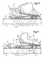
- FIG. 1 and 2 is represented the front of a shoe 1 which is connected to a sports article such as a cross-country ski or hiking 2 by means of a fastening device 3 according to the present invention.
- the fixing device 3 comprises a control device 4 of the opening-closure known type, which in the example described is based on the principle of a toggle. Such a controller is already described in the FR 2,638,974 in the name of the plaintiff. Rotation of a control lever 5 of the control member 4 causes translation, inside a hollow front portion 25 of a guide edge 25, 26, of a coupling element which the example described consists of a bent wire 6.
- the guide edge 25, 26, cooperates in a manner known per se with an associated groove 8a formed in the sole 8 of the shoe.
- the coupling element 6 may be constituted by any other elastic means such as for example by a leaf spring having a certain flexibility with respect to a flexion in a longitudinal and vertical plane with respect to the upper face. ski.
- This wire 6 is bent in the shape of a "U” and fixed on the control member 4, on the front side of the ski, by its free ends 19. It extends essentially parallel to the ski 2 to end in a bent section forming a hook 7.
- the length of the coupling element 6 is chosen such that the hook 7 is below an area of the sole 8 of the shoe 1 corresponding to a foot zone included between the tip of the toes and the so-called metatarsophalangeal part.
- the bending of the coupling element 6 corresponds to the natural unwinding of a foot.
- the outer sole 8 of the shoe is provided with a corresponding attachment means 9 adapted to the cooperation with the coupling element.
- This attachment means 9 may consist of a circular section axis, a rectangular section beam, a notch, etc.
- the attachment means is constituted by a metal axis 9 having a circular section.
- the boot 1 is placed on the upper face 10 of the ski so that the attachment pin 9 integral with the outer sole of the boot 1 is inserted into a transverse groove 11 of the guide edge 25, 26, of the 3.
- the bent wire 6 orthogonally crosses the bottom 13 of this groove 11.
- the hook 7 of the bent wire 6 is entirely withdrawn towards the rear of the ski, that is to say right in the drawing, in an associated housing 12 located in the rear zone 26 of the guide edge 25, 26.
- the operating lever 5 is actuated to thereby cause translation of the bent wire 6 and the hook 7 towards the front of the ski, that is to say say left on the drawing, thus leaving the hook 7 of the housing 12.
- the hook 7 is in the groove 11.
- the axis 9 of the sole 8 of the shoe 1 is then completely locked between the hook 7 and a wall 15 limiting the transverse groove 11 towards the front of the ski.
- the shoe 1 is then fixed to the ski 1 by means of the fastening device in this closed position of the control member 4.
- the axis 9 slides up the wall (ramp) 15 of the groove 11, said wall 15 having a shape corresponding essentially to an arc of a circle centered on the front 25a of the guide edge 25 corresponding to a zone "recess" of the bent wire 6.
- the bent wire 6 is bent upwardly within a housing 14 formed in the portion of the guide edge 25 extending from the groove 11 towards the front of the ski 1.
- This housing 14 has a ramp-like upper wall 14a extending from the front end 25a of the guide ramp up to the level of the groove 11, to allow bending and possibly guiding the wire bent 6 during heel lift.
- the upper wall 17 of the guide edge 25 closes the housing 14 upwards.
- the rear end of the upper wall 17 thus constitutes a stop 18 limiting the maximum bending towards the top of the wire 6, as shown in FIG. figure 3 .
- the maximum uplift of the heel of the boot 1 and thus the maximum angle between the sole of the boot 1 and the upper surface of the ski are thus limited by the stop 18, which allows improved control during the entire lifting phase.
- the abutment of the wire 6 against the abutment 18 allows the recovery of efforts, and thus relieves the attachment 19 of the wire 6 front side of the ski.
- the bent wire 6 in the example described is formed by two longitudinal and substantially parallel branches 20, 21, which are connected to one another by a bent crossbar forming the hook 7 in cross section ( Figures 1 to 3 ).
- each longitudinal branch 20, 21 is housed inside a separate housing 14 or 14 'respectively.
- the walls 22, 23, delimiting the housings 14, 14 ', inwards are inclined, upwardly, outwardly, so that the longitudinal branches 20, 21, connected to each other by the 7 are also bent outwardly of the ski in a plane substantially parallel to the ski surface during bending of the wire 6 upwards.
- the branches 20, 21, tend permanently to reach their initial position at the bottom of the housing 14, 14 ', and therefore a restoring force which tends to return the ski 1 or other sport article plated against the heel .
- the bending energy of the wire 6 is restored at the end of the pulse.
- the recessed wire 6 then serves both to conserve the return energy of the ski and to lock the axis 9 secured to the boot 1.
- the vertical walls of the housing 14, 14 ', furthermore form a transverse guide of the coupling element 6, which allows improved control of the ski or sports article during the entire heel lifting phase.
- transverse guidance of the coupling element 6 can be constituted by any other means having transverse guiding properties, such as grooves, tips, etc.
- the bending curve of the wire 6 is determined by factors, such as, for example, the shape of the housings 14, 14 ', particularly the shape and orientation of their internal walls 22, 23, the characteristics of the material of the wire 6, and the way it is fixed and guided in 19, 25.
- the bending of the wire 6 is defined by said parameters in such a way that the part 24 of the sole 8 of the boot 1 situated in front of the attachment means (axis) 9 remains constantly in direct or indirect contact with the when this effect can be obtained by a rounding 24a of said portion 24 of the shoe 1, which is adapted to the bending curve of the coupling element 6.
- control and referencing of the article of sport and in this case skiing which are improved compared to the prior art through the continuous cooperation between the front part of the sole and the surface skiing during all phases of a typical stride of cross-country skiing, both in classic skating.
- the sole 8 comprises a longitudinal groove cooperating with the guide edge 25, 26.
- the guide edge 25, 26 During the course of the portion 24 of the shoe, not only the axis 9 but also the guide edge 25, 26, take up transversal efforts.
Landscapes
- Footwear And Its Accessory, Manufacturing Method And Apparatuses (AREA)
- Massaging Devices (AREA)
- Holders For Apparel And Elements Relating To Apparel (AREA)
Claims (16)
- Bindungsvorrichtung (3) für einen Schuh (1) auf einem Sportartikel (2), welche ein Koppelelement (6) zum Anschluss an den Schuh (1) umfasst, welcher mit einem Befestigungselement (9) verbunden sein kann, welches in einer Zone, welche zwischen dem Ende der Zehen und dem Mittelfußzehenknochengelenk ist, fest verbunden ist, und welches eine Flexibilität hat, so dass man die Ferse und das Befestigungselement (9) des Schuhs heben kann, gekennzeichnet durch Steuermittel, welche einen direkten oder indirekten dauerhaften Kontakt eines Teils (24) der Sohle (8) des Schuhs (1), welcher vor der Anschlusszone durch das Koppelelement (6) angeordnet ist, mit dem Sportartikel (2), wenn man die Ferse des Schuhs (1) anhebt, ermöglichen.
- Vorrichtung nach Anspruch 1, dadurch gekennzeichnet, dass das Koppelelement (6) elastisch ist.
- Vorrichtung nach einem der Ansprüche 1 oder 2, dadurch gekennzeichnet, dass das Koppelelement (6) eine Rückstellkraft ausübt, welche dazu neigt, den Sportartikel gegen die Ferse wiederkehren zu lassen.
- Vorrichtung nach irgendeinem der vorhergehenden Ansprüche, dadurch gekennzeichnet, dass sie einen Anschlag für das Koppelelement (6) umfasst, um den maximalen Winkel zwischen der Schuhsohle und der oberen Oberfläche des Sportartikels zu begrenzen.
- Vorrichtung nach irgendeinem der vorhergehenden Ansprüche, dadurch gekennzeichnet, dass das Befestigungselement (9) des Schuhs in einer Nut (11) der Bindung aufgenommen wird.
- Vorrichtung nach irgendeinem der vorhergehenden Ansprüche, gekennzeichnet durch ein Positionierungselement (25, 26), welches anders ist als das Koppelelement und mit einem entsprechenden Element zusammenwirkt, welches in der Sohle vorgesehen ist, um den Schuh in Querrichtung zu führen.
- Vorrichtung nach Anspruch 6, dadurch gekennzeichnet, dass das Positionierungselement ein Führungsgrat (25, 26) ist.
- Vorrichtung nach der Kombination der Ansprüche 5 und 7, dadurch gekennzeichnet, dass die Nut (11) eine Quernut ist, welche in dem Führungsgrat (25, 26) angeordnet ist.
- Vorrichtung nach einem der Ansprüche 6 bis 8, dadurch gekennzeichnet, dass der vordere Abschnitt (25) des Führungsgrats andauernd in Kontakt mit dem Schuh während der Abrollphase ist.
- Vorrichtung nach irgendeinem der vorhergehenden Ansprüche, dadurch gekennzeichnet, dass das Koppelelement (6) flexibel ist.
- Vorrichtung nach irgendeinem der vorhergehenden Ansprüche, dadurch gekennzeichnet, dass die Steuermittel eine Querführung des Koppelelements (6) umfassen.
- Vorrichtung nach irgendeinem der vorhergehenden Ansprüche, dadurch gekennzeichnet, dass das Kopplungselement durch einen Metallgrat (6). gebildet wird.
- Vorrichtung nach irgendeinem der vorhergehenden Ansprüche, dadurch gekennzeichnet, dass das Kopplungselement durch eine Klinge gebildet wird.
- Vorrichtung nach irgendeinem der vorhergehenden Ansprüche, dadurch gekennzeichnet, dass sich das Koppelelement (6) im Wesentlichen parallel zu dem Sportartikel erstreckt, um in einem gebogenen Abschnitt in Form eines Hakens (7) abzuschließen.
- Vorrichtung nach irgendeinem der vorhergehenden Ansprüche, dadurch gekennzeichnet, dass das Koppelelement (6) mit dem Befestigungselement (9) des Schuhs (1) in der Weise eines Hakens (7) zusammenwirkt, welcher durch ein Steuerorgan (4) zur Öffnung/Schließung gesteuert wird.
- Vorrichtung nach irgendeinem der vorhergehenden Ansprüche, dadurch gekennzeichnet, dass der vordere Abschnitt (24) der Sohle (8) des Schuhs (1) abgerundet ist.
Applications Claiming Priority (3)
| Application Number | Priority Date | Filing Date | Title |
|---|---|---|---|
| FR9515017 | 1995-12-08 | ||
| FR9515017A FR2742060B1 (fr) | 1995-12-08 | 1995-12-08 | Dispositif de fixation d'une chaussure a un article de sport |
| EP96939153A EP0865306B1 (de) | 1995-12-08 | 1996-11-20 | Vorrichtung zum fixieren eines schuhs an einen sportartikel |
Related Parent Applications (1)
| Application Number | Title | Priority Date | Filing Date |
|---|---|---|---|
| EP96939153A Division EP0865306B1 (de) | 1995-12-08 | 1996-11-20 | Vorrichtung zum fixieren eines schuhs an einen sportartikel |
Publications (3)
| Publication Number | Publication Date |
|---|---|
| EP1312397A2 EP1312397A2 (de) | 2003-05-21 |
| EP1312397A3 EP1312397A3 (de) | 2003-08-06 |
| EP1312397B1 true EP1312397B1 (de) | 2009-01-07 |
Family
ID=9485623
Family Applications (2)
| Application Number | Title | Priority Date | Filing Date |
|---|---|---|---|
| EP96939153A Expired - Lifetime EP0865306B1 (de) | 1995-12-08 | 1996-11-20 | Vorrichtung zum fixieren eines schuhs an einen sportartikel |
| EP03001423A Expired - Lifetime EP1312397B1 (de) | 1995-12-08 | 1996-11-20 | Vorrichtung zum Fixieren eines Schuhs an einen Sportartikel |
Family Applications Before (1)
| Application Number | Title | Priority Date | Filing Date |
|---|---|---|---|
| EP96939153A Expired - Lifetime EP0865306B1 (de) | 1995-12-08 | 1996-11-20 | Vorrichtung zum fixieren eines schuhs an einen sportartikel |
Country Status (6)
| Country | Link |
|---|---|
| EP (2) | EP0865306B1 (de) |
| AT (2) | ATE239534T1 (de) |
| DE (2) | DE69637810D1 (de) |
| FR (1) | FR2742060B1 (de) |
| NO (1) | NO309364B1 (de) |
| WO (1) | WO1997021474A1 (de) |
Families Citing this family (16)
| Publication number | Priority date | Publication date | Assignee | Title |
|---|---|---|---|---|
| FR2742060B1 (fr) * | 1995-12-08 | 1998-01-09 | Salomon Sa | Dispositif de fixation d'une chaussure a un article de sport |
| EP0908204A3 (de) * | 1997-10-10 | 1999-04-28 | Rottefella A/S | Touren-, Telemark- oder Langlauf-Skibindung |
| FR2782652B1 (fr) * | 1998-09-02 | 2000-10-06 | Salomon Sa | Dispositif de fixation d'une chaussure a un article de sport |
| US6986526B2 (en) | 2000-06-08 | 2006-01-17 | Rottefella A/S | Arrangement comprising a ski binding and a ski boot |
| DE10254471A1 (de) | 2002-11-21 | 2004-06-03 | Madsus A/S | Ski mit Bindungs-Montagehilfe, Verfahren zur Herstellung eines solchen Ski sowie entsprechende Montagehilfe |
| FR2859110B1 (fr) | 2003-09-03 | 2006-04-07 | Salomon Sa | Systeme de ski de fond avec surface laterale d'appui direct |
| DE102004024881A1 (de) | 2004-05-19 | 2005-07-14 | Rottefella As | Langlauf- oder Telemarkbindung |
| ATE426439T1 (de) | 2005-01-10 | 2009-04-15 | Rottefella As | Ski oder dergleichen schneegleitgerat mit bindungs-montagehilfe |
| FR2882658B1 (fr) | 2005-03-07 | 2007-05-04 | Salomon Sa | Dispositif de fixation a double commande |
| FR2890317B1 (fr) | 2005-09-08 | 2007-11-23 | Salomon Sa | Dispositif de fixation a ancrage perfectionne |
| FR2894836B1 (fr) | 2005-12-16 | 2008-02-22 | Salomon Sa | Ensemble ski de fond et dispositif de fixation de ski de fond |
| FR2899121B1 (fr) | 2006-03-29 | 2008-07-04 | Salomon Sa | Ensemble ski de fond et dispositif de fixation de ski de fond |
| EP2111900B1 (de) | 2008-04-25 | 2011-12-14 | Rottefella AS | Federeinsatz für eine Skibindung |
| NO20101289A1 (no) | 2010-09-15 | 2012-03-16 | Rottefella As | Langrennsbinding, samt fremgangsmate for sammenstilling av nevnte langrennsbinding |
| FR2972642B1 (fr) * | 2011-03-18 | 2017-03-17 | Felisaz Sas Fixations Plum | Lame ressort- selecteur de position verrouillee/deverrouillee pour fixation de ski-alpinisme |
| FR3024374A1 (fr) * | 2014-07-29 | 2016-02-05 | Luc Jacques Marie Saillet | Dispositif de fixation d'une chaussure a un article de sport |
Citations (1)
| Publication number | Priority date | Publication date | Assignee | Title |
|---|---|---|---|---|
| WO1997021474A1 (fr) * | 1995-12-08 | 1997-06-19 | Salomon S.A. | Dispositif de fixation d'une chaussure a un article de sport |
Family Cites Families (5)
| Publication number | Priority date | Publication date | Assignee | Title |
|---|---|---|---|---|
| AT368707B (de) * | 1981-02-26 | 1982-11-10 | Tyrolia Freizeitgeraete | Sicherheitsskibindung |
| DE3306618A1 (de) * | 1983-02-25 | 1984-08-30 | Josef 7550 Rastatt Klagmann | Verfahren zum herstellen eines skilanglaufschuhes |
| IT1204195B (it) * | 1986-04-30 | 1989-03-01 | Nordica Spa | Dispositivo di collegamento calzatura-sci da fondo |
| FR2638974B1 (fr) | 1988-08-16 | 1990-09-21 | Salomon Sa | Fixation de ski de fond de type charniere |
| FR2719230B1 (fr) * | 1994-04-29 | 1996-06-28 | Salomon Sa | Dispositif de fixation d'une chaussure à un ski de fond. |
-
1995
- 1995-12-08 FR FR9515017A patent/FR2742060B1/fr not_active Expired - Fee Related
-
1996
- 1996-11-20 DE DE69637810T patent/DE69637810D1/de not_active Expired - Lifetime
- 1996-11-20 AT AT96939153T patent/ATE239534T1/de not_active IP Right Cessation
- 1996-11-20 WO PCT/FR1996/001833 patent/WO1997021474A1/fr not_active Ceased
- 1996-11-20 EP EP96939153A patent/EP0865306B1/de not_active Expired - Lifetime
- 1996-11-20 EP EP03001423A patent/EP1312397B1/de not_active Expired - Lifetime
- 1996-11-20 DE DE69628030T patent/DE69628030T2/de not_active Expired - Lifetime
- 1996-11-20 AT AT03001423T patent/ATE419909T1/de not_active IP Right Cessation
-
1998
- 1998-06-03 NO NO982522A patent/NO309364B1/no not_active IP Right Cessation
Patent Citations (1)
| Publication number | Priority date | Publication date | Assignee | Title |
|---|---|---|---|---|
| WO1997021474A1 (fr) * | 1995-12-08 | 1997-06-19 | Salomon S.A. | Dispositif de fixation d'une chaussure a un article de sport |
Also Published As
| Publication number | Publication date |
|---|---|
| NO982522L (no) | 1998-06-03 |
| DE69628030T2 (de) | 2004-04-08 |
| EP1312397A2 (de) | 2003-05-21 |
| EP0865306A1 (de) | 1998-09-23 |
| EP1312397A3 (de) | 2003-08-06 |
| EP0865306B1 (de) | 2003-05-07 |
| FR2742060A1 (fr) | 1997-06-13 |
| WO1997021474A1 (fr) | 1997-06-19 |
| ATE419909T1 (de) | 2009-01-15 |
| DE69637810D1 (de) | 2009-02-26 |
| FR2742060B1 (fr) | 1998-01-09 |
| NO982522D0 (no) | 1998-06-03 |
| ATE239534T1 (de) | 2003-05-15 |
| DE69628030D1 (de) | 2003-06-12 |
| NO309364B1 (no) | 2001-01-22 |
Similar Documents
| Publication | Publication Date | Title |
|---|---|---|
| EP1312397B1 (de) | Vorrichtung zum Fixieren eines Schuhs an einen Sportartikel | |
| FR2739788A1 (fr) | Ensemble de fixation d'une chaussure a un organe de glisse | |
| EP0086908B1 (de) | Skischuh | |
| EP0167462B1 (de) | Kombination bestehend aus einem Langlaufski, einer Langlaufskibindung und einem Langlauf schuh | |
| FR2770097A1 (fr) | Semelle de chaussure de sport | |
| CA2195499A1 (fr) | Chaussure de sport | |
| EP0095400B1 (de) | Skibindung für Langlaufski | |
| FR2522512A1 (fr) | Ensemble pour ski de fond | |
| EP0620711B1 (de) | Langlaufschischuh und kombination von schi, bindung und schuh | |
| FR2583272A1 (fr) | Chaussure de ski alpin | |
| FR2640516A1 (fr) | Fixation de securite pour ski destinee a maintenir, de facon declenchable, l'avant d'une chaussure montee sur le ski | |
| FR2595951A1 (fr) | Ensemble constitue par une chaussure de ski de fond ou de randonnee et un dispositif de retenue de l'avant de cette chaussure sur un ski | |
| EP1935461B1 (de) | Mit einem mindestens zwischen zwei Positionen hin und her schaltbaren, beweglichen Knopf ausgestatteter Artikel | |
| EP0984821B1 (de) | Vorrichtung zum verbinden eines schuhs mit einem sportartikel | |
| FR2540392A1 (fr) | Dispositif de fixation d'une chaussure a un ski de fond ou de randonnee | |
| FR2527932A1 (fr) | Ensemble de fixation d'une chaussure a un ski de fond ou de randonnee | |
| FR2771264A1 (fr) | Chaussure destinee a la pratique du ski de fond | |
| EP0332546B1 (de) | Bindung eines Schuhs auf einen Langlaufski | |
| FR2843311A1 (fr) | Dispositif de fixation a accrochage integre | |
| FR2617381A1 (fr) | Chaussure, notamment de ski alpin a tige articulee | |
| WO1998017356A1 (fr) | Dispositif de liaison entre une chaussure et un article de sport | |
| FR2711488A1 (fr) | Chaussure de ski de fond et ensemble ski-fixation-chaussure pour la pratique du ski de fond. | |
| EP1319424A1 (de) | Bindungsanlage für ein Schuh an ein Sportgerät ohne Hebung | |
| FR2577428A1 (fr) | Fixation de ski de fond | |
| EP1608444A2 (de) | Schuhbindung mit einem zweiteiligen verbindungsorgan |
Legal Events
| Date | Code | Title | Description |
|---|---|---|---|
| PUAI | Public reference made under article 153(3) epc to a published international application that has entered the european phase |
Free format text: ORIGINAL CODE: 0009012 |
|
| AC | Divisional application: reference to earlier application |
Ref document number: 0865306 Country of ref document: EP Kind code of ref document: P |
|
| AK | Designated contracting states |
Designated state(s): AT CH DE FI IT LI SE |
|
| PUAL | Search report despatched |
Free format text: ORIGINAL CODE: 0009013 |
|
| AK | Designated contracting states |
Designated state(s): AT CH DE FI IT LI SE |
|
| AKX | Designation fees paid | ||
| 17P | Request for examination filed |
Effective date: 20040106 |
|
| RBV | Designated contracting states (corrected) |
Designated state(s): AT CH DE FI IT LI SE |
|
| REG | Reference to a national code |
Ref country code: DE Ref legal event code: 8566 |
|
| 17Q | First examination report despatched |
Effective date: 20040922 |
|
| GRAP | Despatch of communication of intention to grant a patent |
Free format text: ORIGINAL CODE: EPIDOSNIGR1 |
|
| GRAS | Grant fee paid |
Free format text: ORIGINAL CODE: EPIDOSNIGR3 |
|
| GRAA | (expected) grant |
Free format text: ORIGINAL CODE: 0009210 |
|
| AC | Divisional application: reference to earlier application |
Ref document number: 0865306 Country of ref document: EP Kind code of ref document: P |
|
| AK | Designated contracting states |
Kind code of ref document: B1 Designated state(s): AT CH DE FI IT LI SE |
|
| REG | Reference to a national code |
Ref country code: CH Ref legal event code: EP |
|
| REF | Corresponds to: |
Ref document number: 69637810 Country of ref document: DE Date of ref document: 20090226 Kind code of ref document: P |
|
| PG25 | Lapsed in a contracting state [announced via postgrant information from national office to epo] |
Ref country code: FI Free format text: LAPSE BECAUSE OF FAILURE TO SUBMIT A TRANSLATION OF THE DESCRIPTION OR TO PAY THE FEE WITHIN THE PRESCRIBED TIME-LIMIT Effective date: 20090107 |
|
| PG25 | Lapsed in a contracting state [announced via postgrant information from national office to epo] |
Ref country code: SE Free format text: LAPSE BECAUSE OF FAILURE TO SUBMIT A TRANSLATION OF THE DESCRIPTION OR TO PAY THE FEE WITHIN THE PRESCRIBED TIME-LIMIT Effective date: 20090407 Ref country code: AT Free format text: LAPSE BECAUSE OF FAILURE TO SUBMIT A TRANSLATION OF THE DESCRIPTION OR TO PAY THE FEE WITHIN THE PRESCRIBED TIME-LIMIT Effective date: 20090107 |
|
| PLBE | No opposition filed within time limit |
Free format text: ORIGINAL CODE: 0009261 |
|
| STAA | Information on the status of an ep patent application or granted ep patent |
Free format text: STATUS: NO OPPOSITION FILED WITHIN TIME LIMIT |
|
| 26N | No opposition filed |
Effective date: 20091008 |
|
| REG | Reference to a national code |
Ref country code: CH Ref legal event code: PL |
|
| PG25 | Lapsed in a contracting state [announced via postgrant information from national office to epo] |
Ref country code: LI Free format text: LAPSE BECAUSE OF NON-PAYMENT OF DUE FEES Effective date: 20091130 Ref country code: CH Free format text: LAPSE BECAUSE OF NON-PAYMENT OF DUE FEES Effective date: 20091130 |
|
| PG25 | Lapsed in a contracting state [announced via postgrant information from national office to epo] |
Ref country code: IT Free format text: LAPSE BECAUSE OF FAILURE TO SUBMIT A TRANSLATION OF THE DESCRIPTION OR TO PAY THE FEE WITHIN THE PRESCRIBED TIME-LIMIT Effective date: 20090107 |
|
| PGFP | Annual fee paid to national office [announced via postgrant information from national office to epo] |
Ref country code: DE Payment date: 20121114 Year of fee payment: 17 |
|
| REG | Reference to a national code |
Ref country code: DE Ref legal event code: R119 Ref document number: 69637810 Country of ref document: DE Effective date: 20140603 |
|
| PG25 | Lapsed in a contracting state [announced via postgrant information from national office to epo] |
Ref country code: DE Free format text: LAPSE BECAUSE OF NON-PAYMENT OF DUE FEES Effective date: 20140603 |