EP1312283A1 - Couchette empilable et élément d'angle pour une telle couchette - Google Patents
Couchette empilable et élément d'angle pour une telle couchette Download PDFInfo
- Publication number
- EP1312283A1 EP1312283A1 EP02292757A EP02292757A EP1312283A1 EP 1312283 A1 EP1312283 A1 EP 1312283A1 EP 02292757 A EP02292757 A EP 02292757A EP 02292757 A EP02292757 A EP 02292757A EP 1312283 A1 EP1312283 A1 EP 1312283A1
- Authority
- EP
- European Patent Office
- Prior art keywords
- stackable
- berth
- corner element
- housing
- foot
- Prior art date
- Legal status (The legal status is an assumption and is not a legal conclusion. Google has not performed a legal analysis and makes no representation as to the accuracy of the status listed.)
- Granted
Links
- 239000004744 fabric Substances 0.000 claims description 17
- 238000006073 displacement reaction Methods 0.000 claims description 3
- 230000000295 complement effect Effects 0.000 claims 1
- 210000000056 organ Anatomy 0.000 description 6
- 239000002184 metal Substances 0.000 description 2
- 235000004443 Ricinus communis Nutrition 0.000 description 1
- 240000000528 Ricinus communis Species 0.000 description 1
- 241001080024 Telles Species 0.000 description 1
- 230000015572 biosynthetic process Effects 0.000 description 1
- 239000000470 constituent Substances 0.000 description 1
- 238000003780 insertion Methods 0.000 description 1
- 230000037431 insertion Effects 0.000 description 1
- 238000003754 machining Methods 0.000 description 1
- 238000004519 manufacturing process Methods 0.000 description 1
- 238000000034 method Methods 0.000 description 1
- 238000009958 sewing Methods 0.000 description 1
- 239000007787 solid Substances 0.000 description 1
- 238000003860 storage Methods 0.000 description 1
- 238000003466 welding Methods 0.000 description 1
Images

Classifications
-
- A—HUMAN NECESSITIES
- A47—FURNITURE; DOMESTIC ARTICLES OR APPLIANCES; COFFEE MILLS; SPICE MILLS; SUCTION CLEANERS IN GENERAL
- A47D—FURNITURE SPECIALLY ADAPTED FOR CHILDREN
- A47D7/00—Children's beds
-
- A—HUMAN NECESSITIES
- A47—FURNITURE; DOMESTIC ARTICLES OR APPLIANCES; COFFEE MILLS; SPICE MILLS; SUCTION CLEANERS IN GENERAL
- A47C—CHAIRS; SOFAS; BEDS
- A47C19/00—Bedsteads
- A47C19/20—Multi-stage bedsteads; Bedsteads stackable to multi-stage bedsteads
- A47C19/202—Stacking or nesting bedsteads
Definitions
- the present invention relates to a stackable berth, as well as an element corner for stackable berth.
- Stackable berths like this are often used in nurseries, nurseries and nursery schools. They generally include a canvas stretched in a generally rectangular frame formed by longitudinal elements and transverse connected to each other by corner elements.
- Each corner element is on its underside provided with a foot, and on its upper face provided with a recess aligned on this foot and constituting a housing receiving a similar foot from another bunk stacking on the first berth.
- the feet have an overall shape cylindrical and the housings also have a generally cylindrical shape and have a slight clearance relative to the contour of the feet to allow stacking easy berths on top of each other.
- the housing for receiving a foot of a upper bunk stacked on the bunk is essentially formed by the foot hollow in the lower part open upwards and through a hole in the part upper aligned with the rest of the housing.
- a disadvantage of this type of berth is that the areas corner have a gap or even an elongated hole formed between the fabric and the corner elements. This is also to be avoided for the same reasons as those invoked above.
- the object of the invention is to propose a berth and a corner element which overcome the disadvantages of known berths and which in addition allow a cheaper manufacturing since without machining parts and without inserts usually required for mounting.
- the invention allows also a simplified assembly of the constituent elements of the berth.
- the subject of the invention is a stackable berth comprising a stretched fabric between elongated longitudinal and transverse elements connected to each other by corner elements, each corner element being provided with two holes horizontal receiving and fixing said longitudinal elements and transverse to form together a generally rectangular frame, each corner element being on its lower face provided with a foot, and on its upper face provided with a vertical recess aligned with said foot and constituting a housing for reception of a similar foot from another berth of the same kind piling up on said berth, each corner element having an upper part and a lower part connected to each other, characterized in that said housing reception of a foot is formed in said upper part and that it comprises a lateral opening in the form of a vertical slot opening outwards and extending over substantially the entire height of said housing opening upwards.
- the subject of the invention is also a corner element for a berth. stackable, comprising on its underside a foot, and on its upper face a vertical recess aligned with said foot and constituting a housing for receiving a similar foot of another corner element of the same kind, and two horizontal holes for receiving and fixing elongated longitudinal and transverse elements (3, 4) to form a frame, said corner element having an upper part and a lower part connected to each other, characterized in that said housing is formed in said upper part and that it has a lateral opening under form of a vertical slot opening outwards and extending over substantially the entire height of said housing opening upwards.
- the berth 1 comprises corner elements 2 interconnected by longitudinal and transverse elements 3, 4 which generally consist of metal tubes. These elements together form a framework overall rectangular on which a canvas 5 is stretched as will be described later in reference to figure 7.
- the berth is thus provided with four corner elements 2.
- Each element angle has on its underside a foot 6 and on its upper face a vertical receiving housing 7 aligned with this foot in order to receive a shaped foot corresponding on a similar bunk stacking on the berth immediately lower.
- Each corner element 2 further comprises two horizontal holes of receiving and fixing 8, 9 respectively intended to receive one end of a longitudinal element 3 and one end of a transverse element 4. These holes reception 8, 9 extend substantially perpendicular to each other in a plane horizontal.
- the corner elements are composed of an upper part 10 and a lower part 11.
- the upper part 10 and the lower part 11 may be in one piece and have the general appearance shown in FIG. 5, or be in at least two individual and separate rooms which are connected one to the other when assembling the berth, as will be explained in more detail later.
- the housing of reception 7 is integrally formed in the upper part 10 and comprises a lateral opening in the form of a vertical slot 12 opening outwards and extending over substantially the entire height of the housing 7, opening upwards.
- the width of the lateral opening 12 is such that a foot of an upper berth is kept laterally immobilized in the housing 7 without the possibility of moving outward.
- the housing 7 has a cylindrical shape in the embodiment illustrated on the figures and is performed in a body 13 also cylindrical.
- This body 13 constitutes a male organ (see FIG. 2) able to cooperate with a recess 14 (see Figure 3) on the upper face of the lower part constituting a female member.
- This female organ 14 follows the shape of the male organ 13 and also comprises a lateral opening 15 corresponding to the lateral opening 12 of the part upper 10.
- These male and female organs here have a preferably circular shape.
- the foot 6 is hollow and the male member 13 of the part upper 10 is at its lower end provided with a transverse element 16 forming the bottom and which closes the foot 6 upwards when the upper parts and lower are assembled (see figure 5).
- the end of the member male 13 is provided with a protrusion 17 of reduced section received in a recess 18 at the lower end of the female member 14 when the two parts upper and lower are assembled.
- This protuberance 17 is on its outer face advantageously provided with longitudinal ribs 19 cooperating with the wall of the recess 18 in order to retain therein this protuberance.
- the upper and lower parts 10, 11 of the corner element 2 have a upper lip 20 respectively a lower lip 21 able to be disposed of on either side of the fabric 5 in a corner area 22 (see Figures 8 and 9).
- Means retaining cloth are formed on the underside of the upper lip 20 and on the upper face of the lower lip 21. These retaining means are advantageously formed by the lips themselves and to obtain a force of improved tightening, the upper lip 20 is inclined towards the lower lip 21 of so that these lips form a jaw.
- these means for retaining the fabric 5 are constituted by lugs arranged on the upper face of the lower lip 21 and cooperating with recesses made on the underside of the upper lip 20 or vice versa.
- the upper part 10 further comprises a skirt 23 extending on either side of the lateral opening 12 of the housing 7.
- This skirt constitutes a guide means during the assembly of the two parts 10, 11 of the corner element 2 by sliding against the external face of the lower part 11 in same time as the male organ 13 of the upper part enters the organ female 14 of the lower part 11.
- the skirt also serves as a protection hiding the plane of joint between these two parts when the corner element is made in two parts as shown in figure 6.
- each receiving and fixing hole 8, 9 is formed by a groove 8A, 9A carried out on the upper face of the lower part 11 and arranged opposite a respective analogous groove 8B, 9B made on the underside of the part upper 10 (see Figure 6).
- pairs transverse bushings 24, 25 extend from the bottoms of the grooves 8A, 8B respectively 9A, 9B.
- the sockets of each pair of sockets 24, 25 pass through opposite fixing holes 26 made in the longitudinal elements and transverse.
- the sockets of each pair of sockets 24, 25 are arranged facing each other to allow the introduction of a fixing screw 27 through a fixing hole 28 by which the sockets of the lower part open down.
- the foot 6 of the corner element 2 advantageously has a central hole 29 constituting a fixing hole for a caster 30 by simply snap-fastening the axis of the roulette in this hole.
- the casters remain removable and can advantageously have a brake.
- the fabric 5 is first cut to obtain the desired shape allowing obtaining tubular flanges 31 by folding and welding or sewing. Each angle canvas is cut to receive a corner element 2.
- the fabric 5 is turned over and the longitudinal and lateral elements 3, 4 are introduced into the corresponding tubular flanges 31.
- the ends of each element protrudes from both sides of the tubular rim to allow insertion of the sockets 25 of the upper parts 10 into the holes 26 of the elements longitudinal and lateral 3, 4 which thus remain blocked.
- the lower parts 11 of corner elements are thus closed on the upper parts 10 by introducing the corresponding sockets 24 in the holes on the longitudinal and lateral elements 3, 4.
- the fixing screws 27 are then introduced through the holes 28 on the face lower part of the lower part 11 of the corner element to join it to the part upper 10 by being screwed into the sockets 25.
- the assembly of the berth is thus particularly easy and quick to implement and we no longer need metal inserts in order to stretch the canvas of a side.
- the berth obtained is shown in Figure 8. It is very solid and the longitudinal and lateral elements 3, 4 are entirely blocked in the holes of fixing 8, 9 of the corner elements and can never let go.
- the berth assembly is similar.
- the sockets 25, 26 to the interior of the receiving and fixing holes 8, 9 of the longitudinal elements and transverse 3, 4 have been removed and replaced by more fixing means conventional simply with a fixing screw passing through a hole transverse communicating with the interior of the receiving holes 8, 9 to rest directly against the corresponding element 3, 4 or still crossing a planned turn in the wall of it.
- FIG. 9 shows several berths according to the invention stacked one on the other on others. You no longer need a specially designed storage accessory for stacking since the stack obtained is completely rigid and can additionally easily be moved if the lower berth is fitted with castors 30. This the latter can also be used without difficulty if the casters are fitted with brakes to immobilize it.
Landscapes
- Buffer Packaging (AREA)
- Stackable Containers (AREA)
- Bedding Items (AREA)
- Mattresses And Other Support Structures For Chairs And Beds (AREA)
- Special Chairs (AREA)
- Invalid Beds And Related Equipment (AREA)
- Magnetic Resonance Imaging Apparatus (AREA)
- Basic Packing Technique (AREA)
- Load-Engaging Elements For Cranes (AREA)
- Storage Of Web-Like Or Filamentary Materials (AREA)
- Pens And Brushes (AREA)
- Dowels (AREA)
- Stacking Of Articles And Auxiliary Devices (AREA)
- Rigid Containers With Two Or More Constituent Elements (AREA)
- Chairs Characterized By Structure (AREA)
- Cultivation Of Plants (AREA)
- Purses, Travelling Bags, Baskets, Or Suitcases (AREA)
- Packaging Of Machine Parts And Wound Products (AREA)
- Mutual Connection Of Rods And Tubes (AREA)
Abstract
Description
- la largeur de ladite ouverture latérale est telle qu'un pied d'une couchette supérieure soit maintenu latéralement immobilisé dans ledit logement (7) sans possibilité de déplacement vers l'extérieur ;
- ladite partie supérieure et ladite partie inférieure sont en une seule pièce ;
- ladite partie supérieure et ladite partie inférieure sont en deux pièces séparées reliées l'une à l'autre lors de l'assemblage de la couchette ;
- ledit logement de réception est effectué dans un organe mâle de ladite partie supérieure coopérant par complémentarité de forme avec un organe femelle de ladite partie inférieure comportant une ouverture latérale correspondant à l'ouverture latérale dudit logement ;
- ledit pied est creux, et ledit organe mâle de la partie supérieure est à son extrémité inférieure pourvu d'un élément transversal formant fond refermant ledit pied vers le haut lorsque lesdites parties supérieure et inférieure sont assemblées ;
- ladite partie supérieure et ladite partie inférieure comportent une lèvre supérieure respectivement une lèvre inférieure disposées de part et d'autre de la toile dans une zone d'angle ;
- la lèvre supérieure comporte sur sa face inférieure des moyens de retenue de ladite toile coopérant avec des moyens de retenue disposés sur la face supérieure de ladite lèvre inférieure ;
- la lèvre supérieure est inclinée vers la lèvre inférieure de manière à former avec cette dernière lesdits moyens de retenue de ladite toile lorsque les première et deuxième parties sont assemblées ;
- ladite partie supérieure comporte une jupe s'étendant de part et d'autre de ladite ouverture latérale dudit logement de manière à constituer un moyen de guidage lors de l'assemblage des deux parties, et un moyen de protection lorsque les deux parties sont assemblées ;
- lesdites parties supérieure et inférieure dudit élément d'angle sont fixées l'une à l'autre par des moyens de liaison par vissage ;
- chaque pied comporte à son extrémité libre un trou de fixation d'une roulette.
- ledit logement est effectué dans un organe mâle de ladite partie supérieure coopérant par complémentarité de forme avec un organe femelle de ladite partie inférieure comportant une ouverture latérale correspondant à l'ouverture latérale dudit logement.
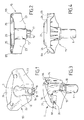
- la figure 1 est une vue de devant en perspective de la partie supérieure d'un élément d'angle selon l'invention ;
- la figure 2 est une vue de derrière latérale de la partie supérieure de la figure 1;
- la figure 3 est une vue de devant en perspective de la partie inférieure d'un élément d'angle selon l'invention ;
- la figure 4 est une vue de derrière latérale de la partie inférieure de la figure 1 ;
- la figure 5 est une vue de devant en perspective de l'élément d'angle selon l'invention ;
- la figure 6 est une vue de derrière en perspective de l'élément d'angle selon l'invention, après assemblage des parties supérieure et inférieure ;
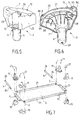
- la figure 7 est une vue schématique en perspective illustrant l'assemblage d'une couchette selon l'invention ;
- la figure 8 est une vue en perspective d'une couchette selon l'invention, après assemblage ;
- la figure 9 est une vue partielle en perspective illustrant l'empilage de plusieurs couchettes selon l'invention, dont la couchette tout en bas est pourvue de roulettes.
Claims (22)
- Couchette empilable comportant une toile (5) tendue entre des éléments allongés longitudinaux et transversaux (3, 4) reliés les uns aux autres par des éléments d'angle (2), chaque élément d'angle étant pourvu de deux trous de réception et de fixation desdits éléments longitudinaux et transversaux (3, 4) pour former ensemble un cadre globalement rectangulaire, chaque élément d'angle (2) étant sur sa face inférieure pourvu d'un pied (6), et sur sa face supérieure pourvu d'un évidement vertical (7) aligné sur ledit pied et constituant un logement de réception d'un pied similaire (6) d'une autre couchette (1) du même genre venant s'empiler sur ladite couchette, chaque élément d'angle (2) présentant une partie supérieure (10) et une partie inférieure (11) reliées l'une à l'autre, caractérisée par le fait que ledit logement de réception d'un pied (7) est formé dans ladite partie supérieure (10) et qu'il comporte une ouverture latérale (12) sous forme d'une fente verticale débouchant vers l'extérieur et s'étendant sur sensiblement toute la hauteur dudit logement (7) en s'ouvrant vers le haut.
- Couchette empilable selon la revendication 1, caractérisée par le fait que la largeur de ladite ouverture latérale (12) est telle qu'un pied (6) d'une couchette supérieure soit maintenu latéralement immobilisé dans ledit logement (7) sans possibilité de déplacement vers l'extérieur.
- Couchette empilable selon la revendication 1 ou 2, caractérisée par le fait que ladite partie supérieure (10) et ladite partie inférieure (11) sont en une seule pièce.
- Couchette empilable selon la revendication 1 ou 2, caractérisée par le fait que ladite partie supérieure (10) et ladite partie inférieure (11) sont en deux pièces séparées reliées l'une à l'autre lors de l'assemblage de la couchette.
- Couchette empilable selon la revendication 4, caractérisée par 1e fait que ledit logement (7) est effectué dans un organe mâle (13) de ladite partie supérieure (10) coopérant par complémentarité de forme avec un organe femelle (14) de ladite partie inférieure (11) comportant une ouverture latérale (15) correspondant à l'ouverture latérale (12) dudit logement (7).
- Couchette empilable selon la revendication 5, dans laquelle ledit pied (6) est creux, caractérisée par le fait que ledit organe mâle (13) de la partie supérieure (10) est à son extrémité inférieure pourvu d'un élément transversal (16) formant fond refermant ledit pied (6) vers le haut lorsque lesdites parties supérieure et inférieure (10, 11) sont assemblées.
- Couchette empilable selon l'une quelconque des revendications 2 à 6, caractérisée par le fait que ladite partie supérieure (10) et ladite partie inférieure (11) comportent une lèvre supérieure (20) respectivement une lèvre inférieure (21) disposées de part et d'autre de la toile (5) dans une zone d'angle (22).
- Couchette empilable selon la revendication 7, caractérisée par le fait que la lèvre supérieure (20) comporte sur sa face inférieure des moyens de retenue de ladite toile (5) coopérant avec des moyens de retenue disposés sur 1a face supérieure de ladite lèvre inférieure (21).
- Couchette empilable selon la revendication 8, caractérisée par le fait que la lèvre supérieure (20) est inclinée vers la lèvre inférieure (21) de manière à former avec cette dernière lesdits moyens de retenue de ladite toile (5) lorsque les première et deuxième parties (10, 11) sont assemblées.
- Couchette empilable selon l'une quelconque des revendications 4 à 9, caractérisée par le fait que ladite partie supérieure (10) comporte une jupe (23) s'étendant de part et d'autre de ladite ouverture latérale (12) dudit logement (7) de manière à constituer un moyen de guidage lors de l'assemblage des deux parties (10, 11), et un moyen de protection lorsque les deux parties sont assemblées.
- Couchette empilable selon l'une quelconque des revendications 3 à 10, caractérisée par le fait que lesdites parties supérieure et inférieure (10, 11) dudit élément d'angle (2) sont fixées l'une à l'autre par des moyens de liaison par vissage (27).
- Couchette empilable selon l'une quelconque des revendications précédentes, caractérisée par le fait que chaque pied comporte à son extrémité libre un trou de fixation (29) d'une roulette (30).
- Elément d'angle pour couchette empilable, comportant sur sa face inférieure un pied (6), et sur sa face supérieure un évidement vertical (7) aligné sur ledit pied et constituant un logement de réception d'un pied similaire (6) d'un autre élément d'angle (2) du même genre, et deux trous horizontaux de réception et de fixation d'éléments allongés longitudinaux et transversaux (3, 4) pour former un cadre, ledit élément d'angle présentant une partie supérieure (10) et une partie inférieure (11) reliées l'une à l'autre, caractérisé par le fait que ledit logement (7) est formé dans ladite partie supérieure (10) et qu'il comporte une ouverture latérale (12) sous forme d'une fente verticale débouchant vers l'extérieur et s'étendant sur sensiblement toute la hauteur dudit logement (7) en s'ouvrant vers le haut.
- Elément d'angle pour couchette empilable selon la revendication 13, caractérisé par le fait que la largeur de ladite ouverture latérale (12) est telle qu'un pied (6) d'un autre élément d'angle (2) soit maintenu latéralement immobilisé dans ledit logement (7) sans possibilité de déplacement vers l'extérieur.
- Elément d'angle pour couchette empilable selon la revendication 13 ou 14, caractérisé par le fait que ladite partie supérieure (10) et ladite partie inférieure (11) sont en une seule pièce.
- Elément d'angle pour couchette empilable selon la revendication 13 ou 14, caractérisé par le fait que ladite partie supérieure (10) et ladite partie inférieure (11) sont en deux pièces séparées reliées l'une à l'autre lors de l'assemblage de la couchette.
- Elément d'angle pour couchette empilable selon la revendication 13 ou 14, caractérisé par le fait que ledit logement de réception (7) est effectué dans un organe mâle (13) de ladite partie supérieure (10) coopérant par complémentarité de forme avec un organe femelle (14) de ladite partie inférieure (11) comportant une ouverture latérale (15) correspondant à l'ouverture latérale (12) dudit logement (7).
- Elément d'angle pour couchette empilable selon l'une quelconque des revendications 13 à 17, caractérisé par le fait que ladite partie supérieure (10) et ladite partie inférieure (11) comportent une lèvre supérieure (20) respectivement une lèvre inférieure (21) aptes à être disposées de part et d'autre d'une toile (5).
- Elément d'angle pour couchette empilable selon la revendication 18, caractérisé par le fait que la lèvre supérieure (20) comporte sur sa face inférieure des moyens de retenue de ladite toile (5) coopérant avec des moyens de retenue disposés sur la face supérieure de ladite lèvre inférieure (21).
- Elément d'angle pour couchette empilable selon la revendication 19, caractérisé par le fait que la lèvre supérieure (20) est inclinée vers la lèvre inférieure (21) de manière à former avec cette dernière lesdits moyens de retenue de ladite toile (5) lorsque les première et deuxième parties (10, 11) sont assemblées.
- Elément d'angle pour couchette empilable selon l'une quelconque des revendications 13 à 20, caractérisé par le fait que ladite partie supérieure (10) comporte une jupe (23) s'étendant de part et d'autre de ladite ouverture latérale (12) dudit logement (7) de manière à constituer un moyen de guidage lors de l'assemblage des deux parties, et un moyen de protection lorsque les deux parties (10, 11) sont assemblées.
- Elément d'angle pour couchette empilable selon l'une quelconque des revendications 13 à 21, caractérisé par le fait que le pied (6) comporte à son extrémité libre un trou de fixation (29) d'une roulette (30).
Applications Claiming Priority (2)
| Application Number | Priority Date | Filing Date | Title |
|---|---|---|---|
| FR0114701A FR2832043B1 (fr) | 2001-11-14 | 2001-11-14 | Couchette empilable et element d'angle pour une telle couchette |
| FR0114701 | 2001-11-14 |
Publications (2)
| Publication Number | Publication Date |
|---|---|
| EP1312283A1 true EP1312283A1 (fr) | 2003-05-21 |
| EP1312283B1 EP1312283B1 (fr) | 2004-08-25 |
Family
ID=8869372
Family Applications (1)
| Application Number | Title | Priority Date | Filing Date |
|---|---|---|---|
| EP02292757A Expired - Lifetime EP1312283B1 (fr) | 2001-11-14 | 2002-11-06 | Couchette empilable et élément d'angle pour une telle couchette |
Country Status (10)
| Country | Link |
|---|---|
| US (1) | US6701548B2 (fr) |
| EP (1) | EP1312283B1 (fr) |
| JP (1) | JP4095882B2 (fr) |
| CN (1) | CN1232207C (fr) |
| AT (1) | ATE274318T1 (fr) |
| DE (1) | DE60201061T2 (fr) |
| DK (1) | DK1312283T3 (fr) |
| ES (1) | ES2227409T3 (fr) |
| FR (1) | FR2832043B1 (fr) |
| PT (1) | PT1312283E (fr) |
Cited By (2)
| Publication number | Priority date | Publication date | Assignee | Title |
|---|---|---|---|---|
| WO2018069556A1 (fr) * | 2016-10-14 | 2018-04-19 | Poveda Rosa Salvador Jose | Lit ou hamac |
| FR3091479A1 (fr) | 2019-01-07 | 2020-07-10 | Wesco | couchette notamment empilable |
Families Citing this family (28)
| Publication number | Priority date | Publication date | Assignee | Title |
|---|---|---|---|---|
| CA2413675C (fr) * | 2002-12-06 | 2010-07-13 | Wellmaster Pipe And Supply Inc. | Corniere monopiece |
| CA2435453C (fr) * | 2003-07-16 | 2008-08-05 | Robert James Hunter | Ensemble de conversion d'un lit pliant a pieds croises en lit pliant etage |
| US7313835B1 (en) * | 2003-12-18 | 2008-01-01 | Elizabeth Hodges | Port-a-cot |
| US7086100B1 (en) * | 2005-05-11 | 2006-08-08 | Lo Feng-Jung | Joining assembly for child's bed |
| US7296310B2 (en) * | 2005-08-22 | 2007-11-20 | Milliken & Company | Adjustable mattress foundation |
| KR200452056Y1 (ko) | 2008-12-08 | 2011-02-01 | 문성수 | 조립식 침대 |
| TW201036575A (en) * | 2009-04-03 | 2010-10-16 | Zhong-Ji Wei | Assembled bed |
| TW201110918A (en) * | 2009-09-25 | 2011-04-01 | Zhong-Ji Wei | Safety assembly bed |
| US8739333B2 (en) | 2010-04-05 | 2014-06-03 | Central City Concern | Bedbug infestation-resistant bed |
| US8468713B2 (en) * | 2010-08-23 | 2013-06-25 | Karen Marie Evans | Contact lens case drying and storage rack assembly |
| US8919284B2 (en) * | 2012-04-20 | 2014-12-30 | Starmark Pet Products, Inc. | Animal bed |
| US9009887B2 (en) * | 2013-07-08 | 2015-04-21 | Delsun Co., Ltd. | Travel cot |
| US20150059089A1 (en) * | 2013-08-28 | 2015-03-05 | Matthew Falkiner | Portable Cot Apparatus for Hands and Legs Free Inflight Sleeping |
| USD731199S1 (en) * | 2013-12-03 | 2015-06-09 | Chih-Chi Wei | Children's cot without corner gaps |
| USD747116S1 (en) | 2014-07-21 | 2016-01-12 | Foundations Worldwide, Inc. | Cot |
| US9398815B2 (en) * | 2014-07-21 | 2016-07-26 | Foundations Worldwide, Inc. | Cot |
| US10045629B2 (en) * | 2014-10-14 | 2018-08-14 | Wood Designs | Stackable leg |
| KR101598721B1 (ko) * | 2014-12-19 | 2016-02-29 | 서기곤 | 높이조절장치 및 이를 이용한 야전침대 |
| USD787873S1 (en) * | 2015-06-18 | 2017-05-30 | ECR4Kids, L.P. | Corner leg for cot |
| CA2960350C (fr) * | 2017-03-09 | 2024-05-21 | BATRIK Medical Manufacturing Inc. | Escabeau dote d'une protection antimicrobienne |
| JP6766725B2 (ja) * | 2017-03-27 | 2020-10-14 | 豊田合成株式会社 | 発泡樹脂成形体 |
| US10898006B2 (en) * | 2017-08-03 | 2021-01-26 | The Pet Cot Company | Cot and corner connector therefor |
| US10610723B2 (en) * | 2018-04-10 | 2020-04-07 | Balanced Body, Inc. | Ultra classic reformer apparatus |
| JP7197885B2 (ja) * | 2018-06-11 | 2022-12-28 | グローバル電子株式会社 | 体動検知ベッド |
| US20210337975A1 (en) * | 2020-04-30 | 2021-11-04 | Holt Sales and Service, LLC | Modular, Compact, Stackable Beds And Associated Systems And Methods |
| KR102439068B1 (ko) * | 2020-12-17 | 2022-09-01 | 주식회사 에코브 | 가구 프레임용 연결부재 및 이를 이용한 프레임 조립체 |
| JP2024063691A (ja) * | 2022-10-26 | 2024-05-13 | コクヨ株式会社 | ソファ |
| USD1116756S1 (en) * | 2024-07-09 | 2026-03-10 | Zhejiang Potential Toy Co., Ltd | Foot of bed |
Citations (4)
| Publication number | Priority date | Publication date | Assignee | Title |
|---|---|---|---|---|
| US2863568A (en) * | 1954-03-04 | 1958-12-09 | Paltier Corp | Bearing supports for pallet stacking |
| US2924830A (en) * | 1953-07-02 | 1960-02-16 | Long Ruth Nash De | Nesting furniture structure |
| US4958390A (en) * | 1988-11-04 | 1990-09-25 | Holbrook-Patterson, Inc. | Rest cot assembly |
| EP1219209A1 (fr) * | 2000-12-27 | 2002-07-03 | Interdidak, S.L. | Pied pour lit empilable |
Family Cites Families (1)
| Publication number | Priority date | Publication date | Assignee | Title |
|---|---|---|---|---|
| US6513178B1 (en) * | 2000-05-15 | 2003-02-04 | Agi, Llc | Cot assembly |
-
2001
- 2001-11-14 FR FR0114701A patent/FR2832043B1/fr not_active Expired - Fee Related
-
2002
- 2002-11-06 DE DE60201061T patent/DE60201061T2/de not_active Expired - Lifetime
- 2002-11-06 DK DK02292757T patent/DK1312283T3/da active
- 2002-11-06 ES ES02292757T patent/ES2227409T3/es not_active Expired - Lifetime
- 2002-11-06 PT PT02292757T patent/PT1312283E/pt unknown
- 2002-11-06 AT AT02292757T patent/ATE274318T1/de active
- 2002-11-06 EP EP02292757A patent/EP1312283B1/fr not_active Expired - Lifetime
- 2002-11-13 CN CN02150491.1A patent/CN1232207C/zh not_active Expired - Fee Related
- 2002-11-14 JP JP2002331004A patent/JP4095882B2/ja not_active Expired - Fee Related
- 2002-11-14 US US10/293,352 patent/US6701548B2/en not_active Expired - Lifetime
Patent Citations (4)
| Publication number | Priority date | Publication date | Assignee | Title |
|---|---|---|---|---|
| US2924830A (en) * | 1953-07-02 | 1960-02-16 | Long Ruth Nash De | Nesting furniture structure |
| US2863568A (en) * | 1954-03-04 | 1958-12-09 | Paltier Corp | Bearing supports for pallet stacking |
| US4958390A (en) * | 1988-11-04 | 1990-09-25 | Holbrook-Patterson, Inc. | Rest cot assembly |
| EP1219209A1 (fr) * | 2000-12-27 | 2002-07-03 | Interdidak, S.L. | Pied pour lit empilable |
Cited By (4)
| Publication number | Priority date | Publication date | Assignee | Title |
|---|---|---|---|---|
| WO2018069556A1 (fr) * | 2016-10-14 | 2018-04-19 | Poveda Rosa Salvador Jose | Lit ou hamac |
| US10154735B2 (en) | 2016-10-14 | 2018-12-18 | Salvador Jose POVEDA ROSA | Bed or hammock |
| FR3091479A1 (fr) | 2019-01-07 | 2020-07-10 | Wesco | couchette notamment empilable |
| WO2020144422A1 (fr) | 2019-01-07 | 2020-07-16 | Wesco | Couchette notamment empilable |
Also Published As
| Publication number | Publication date |
|---|---|
| PT1312283E (pt) | 2004-12-31 |
| DE60201061D1 (de) | 2004-09-30 |
| JP2003159157A (ja) | 2003-06-03 |
| ES2227409T3 (es) | 2005-04-01 |
| EP1312283B1 (fr) | 2004-08-25 |
| CN1418590A (zh) | 2003-05-21 |
| DK1312283T3 (da) | 2005-02-28 |
| US6701548B2 (en) | 2004-03-09 |
| ATE274318T1 (de) | 2004-09-15 |
| JP4095882B2 (ja) | 2008-06-04 |
| FR2832043B1 (fr) | 2005-06-10 |
| FR2832043A1 (fr) | 2003-05-16 |
| US20030088914A1 (en) | 2003-05-15 |
| CN1232207C (zh) | 2005-12-21 |
| DE60201061T2 (de) | 2005-09-29 |
| HK1054849A1 (en) | 2003-12-19 |
Similar Documents
| Publication | Publication Date | Title |
|---|---|---|
| EP1312283B1 (fr) | Couchette empilable et élément d'angle pour une telle couchette | |
| FR2587576A1 (fr) | Coffret pour loger des cartes de circuits | |
| FR2533123A1 (fr) | Dispositif formant ossature notamment pour meuble de rangement, par exemple un rayonnage | |
| CH650315A5 (fr) | Organe d'assemblage et dispositif d'assemblage comportant au moins deux organes d'assemblage. | |
| FR2717665A1 (fr) | Balancelle pliante. | |
| BE1001456A3 (fr) | Jouet en forme d'arche de noe. | |
| FR2528100A1 (fr) | Charniere pour siege de toilettes | |
| BE1013074A3 (fr) | Structure de balancelle autoportante pour jardin. | |
| FR3125401A3 (fr) | Dispositif d’adaptation d’un pied d’arbre de Noël | |
| FR2734463A3 (fr) | Ensemble de cadre pour un tableau | |
| FR2666241A1 (fr) | Joueur pour baby-foot. | |
| EP1876928B1 (fr) | Embout de lattes tripode a debattement hautement stabilise | |
| FR2468018A1 (fr) | Element d'assemblage extensible pour elements tubulaires | |
| WO1981002970A1 (fr) | Assemblage elastique par exemple bracelet ou bague | |
| CA2107418A1 (fr) | Element cadre articule pour mobilier modulable et charniere pour l'articulation de deux elements cadre entre eux | |
| FR2578298A1 (fr) | Elements assemblables pour la realisation de meubles de rangement | |
| EP0291433A1 (fr) | Chaise pliante | |
| EP0721069A1 (fr) | Pièce d'assemblage pour la fixation de barreaux sans partie saillante | |
| WO2010023404A2 (fr) | Ensemble modulaire de construction | |
| EP0335810B1 (fr) | Assemblage de coin pour table de découpe | |
| EP0011546B1 (fr) | Meubles pliants et gerbables | |
| FR3100698A1 (fr) | Article de puériculture, adapté à recevoir un enfant | |
| FR2627218A1 (fr) | Serrure a combinaison | |
| BE1017338A6 (fr) | Structure de decor. | |
| FR2756158A3 (fr) | Articulation pour parc a enfants pliable |
Legal Events
| Date | Code | Title | Description |
|---|---|---|---|
| PUAI | Public reference made under article 153(3) epc to a published international application that has entered the european phase |
Free format text: ORIGINAL CODE: 0009012 |
|
| AK | Designated contracting states |
Designated state(s): AT BE BG CH CY CZ DE DK EE ES FI FR GB GR IE IT LI LU MC NL PT SE SK TR |
|
| AX | Request for extension of the european patent |
Extension state: AL LT LV MK RO SI |
|
| 17P | Request for examination filed |
Effective date: 20031118 |
|
| AKX | Designation fees paid |
Designated state(s): AT BE BG CH CY CZ DE DK EE ES FI FR GB GR IE IT LI LU MC NL PT SE SK TR |
|
| AXX | Extension fees paid |
Extension state: RO Payment date: 20031118 |
|
| GRAP | Despatch of communication of intention to grant a patent |
Free format text: ORIGINAL CODE: EPIDOSNIGR1 |
|
| GRAS | Grant fee paid |
Free format text: ORIGINAL CODE: EPIDOSNIGR3 |
|
| GRAA | (expected) grant |
Free format text: ORIGINAL CODE: 0009210 |
|
| AK | Designated contracting states |
Kind code of ref document: B1 Designated state(s): AT BE BG CH CY CZ DE DK EE ES FI FR GB GR IE IT LI LU MC NL PT SE SK TR |
|
| AX | Request for extension of the european patent |
Extension state: RO |
|
| PG25 | Lapsed in a contracting state [announced via postgrant information from national office to epo] |
Ref country code: TR Free format text: LAPSE BECAUSE OF FAILURE TO SUBMIT A TRANSLATION OF THE DESCRIPTION OR TO PAY THE FEE WITHIN THE PRESCRIBED TIME-LIMIT Effective date: 20040825 Ref country code: EE Free format text: LAPSE BECAUSE OF FAILURE TO SUBMIT A TRANSLATION OF THE DESCRIPTION OR TO PAY THE FEE WITHIN THE PRESCRIBED TIME-LIMIT Effective date: 20040825 Ref country code: BG Free format text: LAPSE BECAUSE OF FAILURE TO SUBMIT A TRANSLATION OF THE DESCRIPTION OR TO PAY THE FEE WITHIN THE PRESCRIBED TIME-LIMIT Effective date: 20040825 Ref country code: CZ Free format text: LAPSE BECAUSE OF FAILURE TO SUBMIT A TRANSLATION OF THE DESCRIPTION OR TO PAY THE FEE WITHIN THE PRESCRIBED TIME-LIMIT Effective date: 20040825 Ref country code: SK Free format text: LAPSE BECAUSE OF FAILURE TO SUBMIT A TRANSLATION OF THE DESCRIPTION OR TO PAY THE FEE WITHIN THE PRESCRIBED TIME-LIMIT Effective date: 20040825 Ref country code: CY Free format text: LAPSE BECAUSE OF FAILURE TO SUBMIT A TRANSLATION OF THE DESCRIPTION OR TO PAY THE FEE WITHIN THE PRESCRIBED TIME-LIMIT Effective date: 20040825 |
|
| REG | Reference to a national code |
Ref country code: GB Ref legal event code: FG4D Free format text: NOT ENGLISH |
|
| REG | Reference to a national code |
Ref country code: CH Ref legal event code: EP |
|
| REG | Reference to a national code |
Ref country code: IE Ref legal event code: FG4D Free format text: FRENCH |
|
| REF | Corresponds to: |
Ref document number: 60201061 Country of ref document: DE Date of ref document: 20040930 Kind code of ref document: P |
|
| REG | Reference to a national code |
Ref country code: SE Ref legal event code: TRGR |
|
| PG25 | Lapsed in a contracting state [announced via postgrant information from national office to epo] |
Ref country code: MC Free format text: LAPSE BECAUSE OF NON-PAYMENT OF DUE FEES Effective date: 20041130 |
|
| REG | Reference to a national code |
Ref country code: GR Ref legal event code: EP Ref document number: 20040403920 Country of ref document: GR |
|
| REG | Reference to a national code |
Ref country code: PT Ref legal event code: SC4A Free format text: AVAILABILITY OF NATIONAL TRANSLATION Effective date: 20041108 |
|
| LTIE | Lt: invalidation of european patent or patent extension |
Effective date: 20040825 |
|
| REG | Reference to a national code |
Ref country code: DK Ref legal event code: T3 |
|
| REG | Reference to a national code |
Ref country code: ES Ref legal event code: FG2A Ref document number: 2227409 Country of ref document: ES Kind code of ref document: T3 |
|
| PLBE | No opposition filed within time limit |
Free format text: ORIGINAL CODE: 0009261 |
|
| STAA | Information on the status of an ep patent application or granted ep patent |
Free format text: STATUS: NO OPPOSITION FILED WITHIN TIME LIMIT |
|
| 26N | No opposition filed |
Effective date: 20050526 |
|
| PG25 | Lapsed in a contracting state [announced via postgrant information from national office to epo] |
Ref country code: CH Free format text: LAPSE BECAUSE OF NON-PAYMENT OF DUE FEES Effective date: 20061130 Ref country code: LI Free format text: LAPSE BECAUSE OF NON-PAYMENT OF DUE FEES Effective date: 20061130 |
|
| REG | Reference to a national code |
Ref country code: CH Ref legal event code: PL |
|
| REG | Reference to a national code |
Ref country code: FR Ref legal event code: PLFP Year of fee payment: 14 |
|
| REG | Reference to a national code |
Ref country code: FR Ref legal event code: PLFP Year of fee payment: 15 |
|
| REG | Reference to a national code |
Ref country code: FR Ref legal event code: PLFP Year of fee payment: 16 |
|
| PGFP | Annual fee paid to national office [announced via postgrant information from national office to epo] |
Ref country code: GR Payment date: 20171114 Year of fee payment: 16 |
|
| PGFP | Annual fee paid to national office [announced via postgrant information from national office to epo] |
Ref country code: EE Payment date: 20181126 Year of fee payment: 17 Ref country code: DK Payment date: 20181122 Year of fee payment: 17 |
|
| PG25 | Lapsed in a contracting state [announced via postgrant information from national office to epo] |
Ref country code: GR Free format text: LAPSE BECAUSE OF NON-PAYMENT OF DUE FEES Effective date: 20190605 |
|
| REG | Reference to a national code |
Ref country code: FI Ref legal event code: MAE |
|
| REG | Reference to a national code |
Ref country code: DK Ref legal event code: EBP Effective date: 20191130 |
|
| REG | Reference to a national code |
Ref country code: SE Ref legal event code: EUG |
|
| PG25 | Lapsed in a contracting state [announced via postgrant information from national office to epo] |
Ref country code: FI Free format text: LAPSE BECAUSE OF NON-PAYMENT OF DUE FEES Effective date: 20191106 |
|
| PG25 | Lapsed in a contracting state [announced via postgrant information from national office to epo] |
Ref country code: SE Free format text: LAPSE BECAUSE OF NON-PAYMENT OF DUE FEES Effective date: 20191107 |
|
| PG25 | Lapsed in a contracting state [announced via postgrant information from national office to epo] |
Ref country code: DK Free format text: LAPSE BECAUSE OF NON-PAYMENT OF DUE FEES Effective date: 20191130 |
|
| PGFP | Annual fee paid to national office [announced via postgrant information from national office to epo] |
Ref country code: NL Payment date: 20201125 Year of fee payment: 19 |
|
| PGFP | Annual fee paid to national office [announced via postgrant information from national office to epo] |
Ref country code: LU Payment date: 20201118 Year of fee payment: 19 Ref country code: FR Payment date: 20201120 Year of fee payment: 19 Ref country code: GB Payment date: 20201120 Year of fee payment: 19 Ref country code: AT Payment date: 20201119 Year of fee payment: 19 Ref country code: DE Payment date: 20201119 Year of fee payment: 19 Ref country code: IT Payment date: 20201124 Year of fee payment: 19 Ref country code: PT Payment date: 20201029 Year of fee payment: 19 Ref country code: IE Payment date: 20201120 Year of fee payment: 19 |
|
| PGFP | Annual fee paid to national office [announced via postgrant information from national office to epo] |
Ref country code: BE Payment date: 20201125 Year of fee payment: 19 |
|
| PGFP | Annual fee paid to national office [announced via postgrant information from national office to epo] |
Ref country code: ES Payment date: 20210122 Year of fee payment: 19 |
|
| REG | Reference to a national code |
Ref country code: DE Ref legal event code: R119 Ref document number: 60201061 Country of ref document: DE |
|
| REG | Reference to a national code |
Ref country code: NL Ref legal event code: MM Effective date: 20211201 |
|
| REG | Reference to a national code |
Ref country code: AT Ref legal event code: MM01 Ref document number: 274318 Country of ref document: AT Kind code of ref document: T Effective date: 20211106 |
|
| GBPC | Gb: european patent ceased through non-payment of renewal fee |
Effective date: 20211106 |
|
| PG25 | Lapsed in a contracting state [announced via postgrant information from national office to epo] |
Ref country code: PT Free format text: LAPSE BECAUSE OF NON-PAYMENT OF DUE FEES Effective date: 20220506 Ref country code: LU Free format text: LAPSE BECAUSE OF NON-PAYMENT OF DUE FEES Effective date: 20211106 Ref country code: BE Free format text: LAPSE BECAUSE OF NON-PAYMENT OF DUE FEES Effective date: 20211130 |
|
| REG | Reference to a national code |
Ref country code: BE Ref legal event code: MM Effective date: 20211130 |
|
| PG25 | Lapsed in a contracting state [announced via postgrant information from national office to epo] |
Ref country code: AT Free format text: LAPSE BECAUSE OF NON-PAYMENT OF DUE FEES Effective date: 20211106 |
|
| PG25 | Lapsed in a contracting state [announced via postgrant information from national office to epo] |
Ref country code: NL Free format text: LAPSE BECAUSE OF NON-PAYMENT OF DUE FEES Effective date: 20211201 |
|
| PG25 | Lapsed in a contracting state [announced via postgrant information from national office to epo] |
Ref country code: IE Free format text: LAPSE BECAUSE OF NON-PAYMENT OF DUE FEES Effective date: 20211106 Ref country code: GB Free format text: LAPSE BECAUSE OF NON-PAYMENT OF DUE FEES Effective date: 20211106 Ref country code: DE Free format text: LAPSE BECAUSE OF NON-PAYMENT OF DUE FEES Effective date: 20220601 |
|
| PG25 | Lapsed in a contracting state [announced via postgrant information from national office to epo] |
Ref country code: FR Free format text: LAPSE BECAUSE OF NON-PAYMENT OF DUE FEES Effective date: 20211130 |
|
| PG25 | Lapsed in a contracting state [announced via postgrant information from national office to epo] |
Ref country code: PT Free format text: LAPSE BECAUSE OF EXPIRATION OF PROTECTION Effective date: 20221116 Ref country code: IT Free format text: LAPSE BECAUSE OF NON-PAYMENT OF DUE FEES Effective date: 20211106 |
|
| REG | Reference to a national code |
Ref country code: ES Ref legal event code: FD2A Effective date: 20230207 |
|
| PG25 | Lapsed in a contracting state [announced via postgrant information from national office to epo] |
Ref country code: ES Free format text: LAPSE BECAUSE OF NON-PAYMENT OF DUE FEES Effective date: 20211107 |
|
| PG25 | Lapsed in a contracting state [announced via postgrant information from national office to epo] |
Ref country code: PT Free format text: LAPSE BECAUSE OF NON-PAYMENT OF DUE FEES Effective date: 20211108 |
|
| PG25 | Lapsed in a contracting state [announced via postgrant information from national office to epo] |
Ref country code: PT Free format text: LAPSE BECAUSE OF NON-PAYMENT OF DUE FEES Effective date: 20211108 |