EP1310942A2 - Ultraschallsensor mit einem topfförmigen Gehäuse und zugehöriges Herstellungsverfahren - Google Patents
Ultraschallsensor mit einem topfförmigen Gehäuse und zugehöriges Herstellungsverfahren Download PDFInfo
- Publication number
- EP1310942A2 EP1310942A2 EP02020785A EP02020785A EP1310942A2 EP 1310942 A2 EP1310942 A2 EP 1310942A2 EP 02020785 A EP02020785 A EP 02020785A EP 02020785 A EP02020785 A EP 02020785A EP 1310942 A2 EP1310942 A2 EP 1310942A2
- Authority
- EP
- European Patent Office
- Prior art keywords
- membrane
- ultrasonic sensor
- wall
- foamed
- volume piece
- Prior art date
- Legal status (The legal status is an assumption and is not a legal conclusion. Google has not performed a legal analysis and makes no representation as to the accuracy of the status listed.)
- Granted
Links
- 238000004519 manufacturing process Methods 0.000 title claims abstract description 5
- 238000000034 method Methods 0.000 title claims description 14
- 239000012528 membrane Substances 0.000 claims abstract description 108
- 239000000463 material Substances 0.000 claims description 18
- 238000005187 foaming Methods 0.000 claims description 8
- 238000012545 processing Methods 0.000 claims description 4
- 239000007769 metal material Substances 0.000 claims description 3
- 239000002184 metal Substances 0.000 abstract 1
- 238000002604 ultrasonography Methods 0.000 description 7
- 239000000919 ceramic Substances 0.000 description 5
- 238000003801 milling Methods 0.000 description 2
- 238000012805 post-processing Methods 0.000 description 2
- 238000002360 preparation method Methods 0.000 description 2
- 239000011343 solid material Substances 0.000 description 2
- 238000007514 turning Methods 0.000 description 2
- XAGFODPZIPBFFR-UHFFFAOYSA-N aluminium Chemical compound [Al] XAGFODPZIPBFFR-UHFFFAOYSA-N 0.000 description 1
- 229910052782 aluminium Inorganic materials 0.000 description 1
- 239000003795 chemical substances by application Substances 0.000 description 1
- 238000013016 damping Methods 0.000 description 1
- 238000001514 detection method Methods 0.000 description 1
- 238000005516 engineering process Methods 0.000 description 1
- 239000006260 foam Substances 0.000 description 1
- 239000011440 grout Substances 0.000 description 1
- 230000001771 impaired effect Effects 0.000 description 1
- 238000003754 machining Methods 0.000 description 1
- 238000013017 mechanical damping Methods 0.000 description 1
- 229920001296 polysiloxane Polymers 0.000 description 1
- 238000007789 sealing Methods 0.000 description 1
- 239000002689 soil Substances 0.000 description 1
- 238000003856 thermoforming Methods 0.000 description 1
Images
Classifications
-
- G—PHYSICS
- G10—MUSICAL INSTRUMENTS; ACOUSTICS
- G10K—SOUND-PRODUCING DEVICES; METHODS OR DEVICES FOR PROTECTING AGAINST, OR FOR DAMPING, NOISE OR OTHER ACOUSTIC WAVES IN GENERAL; ACOUSTICS NOT OTHERWISE PROVIDED FOR
- G10K11/00—Methods or devices for transmitting, conducting or directing sound in general; Methods or devices for protecting against, or for damping, noise or other acoustic waves in general
- G10K11/002—Devices for damping, suppressing, obstructing or conducting sound in acoustic devices
-
- G—PHYSICS
- G10—MUSICAL INSTRUMENTS; ACOUSTICS
- G10K—SOUND-PRODUCING DEVICES; METHODS OR DEVICES FOR PROTECTING AGAINST, OR FOR DAMPING, NOISE OR OTHER ACOUSTIC WAVES IN GENERAL; ACOUSTICS NOT OTHERWISE PROVIDED FOR
- G10K9/00—Devices in which sound is produced by vibrating a diaphragm or analogous element, e.g. fog horns, vehicle hooters or buzzers
- G10K9/12—Devices in which sound is produced by vibrating a diaphragm or analogous element, e.g. fog horns, vehicle hooters or buzzers electrically operated
- G10K9/122—Devices in which sound is produced by vibrating a diaphragm or analogous element, e.g. fog horns, vehicle hooters or buzzers electrically operated using piezoelectric driving means
Definitions
- the invention relates to an ultrasonic sensor with a cup-shaped membrane, which has a vibratory Membrane bottom and a membrane bottom at least Having partially surrounding membrane wall.
- ultrasonic sensors are found, for example Close-range detection systems of motor vehicles Use.
- the invention also relates to a method for Production of such an ultrasonic sensor.
- Known ultrasonic sensors also have Decoupling media between the membrane and a the Membrane receiving housing on.
- the individual components of the ultrasonic sensor individually produced and joined together by nesting.
- the positioning of the membrane is subject unwanted due to component tolerances Tolerance variations.
- decoupling media required that the vibration of the diaphragm against the Decouple housing.
- the present invention is based on the object to provide an ultrasonic sensor in which a exact positioning of the membrane is possible and the has as few components.
- the Membrane wall at least in sections a foam-like Structure has.
- Decoupling media between the membrane or the membrane wall and a housing, if one such is provided are not required.
- the membrane wall can be a foam-like Possess structure that has a reduced ability too has swinging.
- Such a membrane wall takes over the function of the known from the prior art Decoupling media.
- the decoupling media not required are, a component reduction is achieved.
- the membrane bottom has no foam-like structure. This ensures that the membrane bottom its retains and maintains vibrational properties of ultrasound can be used.
- Another embodiment of the invention provides that the membrane wall and the membrane bottom at least partially have a foam-like structure. This allows the areas of the membrane bottom that are not to be used for generating ultrasound, a have reduced vibrational ability. Such areas are particularly necessary when ultrasonic lobes to be generated with a defined geometry.
- Another advantageous embodiment of the invention is characterized by the fact that the membrane bottom a having defoamed structure. It is conceivable that the membrane bottom is initially formed like a foam and then, for example, by compressing the foam-like section that is to form the membrane bottom, is defoamed.
- the membrane bottom has the same Material like the membrane wall on.
- the membrane bottom can but also from the same material as the membrane wall exist, the diaphragm bottom then not foamed and then defoamed, but solid Material exists.
- the Membrane bottom made of a different material like the Membrane wall.
- the membrane floor can hereby for example, from particularly suitable material, such as for example, be a metallic material.
- the membrane wall is, for example made of a foamed material that is a foamy Owns structure.
- the ultrasonic sensor has no housing.
- the Outside of the membrane wall preferably completely has a foamed structure, looks here Tightening agent for placement on a component ago.
- One Such component may in particular a bumper of a Be a vehicle.
- Such an embodiment of the invention has the advantage that neither a decoupling medium nor a extra housing is required.
- the from the foamy Structure existing membrane wall thus includes the Decoupling medium and the housing. Because of the achieved Component reduction may be the ultrasonic sensor positioned accurately positioned at the specified location become. Undesirable tolerance deviations resulting from the Individual tolerances of individual components according to the state of Technology results do not occur.
- For precise position Arrangement of the ultrasonic sensor to the component can be a point or line contact be provided.
- the object mentioned above is also by a Process for the preparation of an inventive Ultrasonic sensor dissolved, characterized thereby, that a base material foamed to a volume piece is and the volume piece at least partially the Membrane wall and / or the membrane bottom forms. areas the membrane, which is not capable of generating ultrasound Consequently, use does not exist Solid material, but of a foam-like structure, the has a reduced vibration ability.
- the volume piece before use as Membrane wall and / or membrane soil are processed.
- Deep-drawing the volume piece Through the thermoforming process can from a foamed, preferably cylindrical Volume piece, a cup-shaped membrane can be realized.
- the membrane wall is formed by the deep drawing process insignificantly impaired.
- the Membrane bottom during the deep drawing process advantageously defoamed, allowing him to generate ultrasound Can be used.
- a processing of the foamed volume piece and / or the deep drawn volume piece can advantageously also done sensational. It has turned out to be advantageous and turning Milling the foamed volume proved.
- the foaming takes place in a foaming mold.
- the foaming of the Volume piece controlled.
- Post-processing is not required.
- the foaming mold advantageously has this Internal dimensions on the outside dimensions of the membrane correspond. This has the advantage of being highly accurate Outside dimensions of the membrane can be realized without any post-processing of the outer surfaces is required. Tolerances can be kept very accurately become.
- the diaphragm bottom by a pickled, not to form foamed material.
- a membrane bottom may be for example of a metallic material.
- the membrane wall becomes a firm connection with the Membrane bottom preferably foamed to the membrane bottom. This has the advantage of having additional funds for Fix the membrane bottom on the membrane wall not required are.
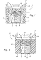
- FIG. 1 shows a known ultrasonic sensor 1 shown.
- the ultrasonic sensor 1 includes a Plastic housing 3 and a cup-shaped Membrane 5 made of aluminum, wherein between the housing 3 and the membrane 5 a rubbery, annular decoupling Medium 7, is present.
- the membrane 5 consists of a membrane bottom 9, the of a membrane wall 11 is included. On the inside the diaphragm bottom 9 is a piezo-ceramic disc 13 arranged. Via an electrical line 15, at the Piezo-ceramic disc 13 ends and another electrical Line 17, the side of the inside of the membrane. 5 caulked, the piezo-ceramic disc 13 with a be subjected to electrical voltage.
- the membrane 5 with a mechanical Damping material 19 filled.
- the damping material 19 has a cutout 21.
- Upper portion of the membrane 5, a rubber part 23 is provided.
- a Silicone grout 25 provided for sealing the upwardly open membrane 5 is a Silicone grout 25 provided. Further covers Housing cover 27, the upwardly open housing 3 from.
- the Housing 3 can via fastening means 29 on a component, for example, a bumper of a vehicle arranged become.
- the Ultrasonic sensor 41 according to the invention according to FIG. 2 a membrane 45 which has a membrane wall 51 of a having foam-like structure.
- the membrane wall 51 takes over the function of the membrane wall 11, the Decoupling medium 7 and the housing 3 a Ultrasonic transducer 1 according to FIG. 1
- FIG. 2 The components corresponding to FIG. 1 are shown in FIG. 2 provided with the corresponding reference numeral.
- the membrane bottom 49 of the membrane 45 has no foam-like, but one defoamed structure.
- Such a defoamed Structure can according to the figure 1 with a piezo ceramic disc 13 are vibrated.
- the ultrasonic sensor 41 according to FIG. 2 has opposite to FIG known ultrasonic sensor 1 according to Figure 1 the decisive advantage that it has fewer components.
- the areas of the diaphragm 45 that are not for vibration and thus used to generate ultrasound should feature a foamed structure, and thus a vibration-damped behavior.
- an ultrasonic transducer 41 for producing an ultrasonic transducer 41 according to FIG. 2 is advantageously a volume piece of a Base material foamed, the outside dimensions of the Membrane 45 has.
- foaming can advantageously take place in a AufMumform, the Has inner dimensions that match the outer dimensions of Diaphragm 45 correspond.
- the membrane bottom 49 for the production of the membrane bottom 49, the preferably cylindrical volume piece such are deep-drawn, that the cup-shaped membrane 51st arises.
- the membrane bottom 49 is thus through Compressing the part of the volume produced in vertical projection above the inner surface of the Membrane bottom 49 is located.
- the material of the membrane bottom 49 is therefore defoamed by the deep-drawing process. By such defoaming, the membrane bottom 49 a sufficient vibration behavior to produce Ultrasound on.
- a processing of the membrane 45 may further by a machining, in particular by turning or Milling, done.
- the membrane bottom can be made of a preferably metallic one Be material.
- Ultrasonic sensor can connect the membrane wall directly to the Membrane bottom are foamed.
- the resulting Membrane then has a membrane wall with a foamy structure and a membrane bottom with none foamy, but preferably a metallic one Structure on.
- the membrane wall and the membrane bottom one such membranes are therefore different Material.
- the ultrasonic sensor 41 shown in FIG. 2 can directly, i. without the provision of an extra housing a component, for example, to a bumper of a Vehicle, to be arranged.
- a Membrane wall made of foamed material becomes a sufficient decoupling ensured.
- the touch of the Outside of the membrane 45 to, for example, a Bumper may advantageously point or line respectively.
Landscapes
- Physics & Mathematics (AREA)
- Engineering & Computer Science (AREA)
- Acoustics & Sound (AREA)
- Multimedia (AREA)
- Measurement Of Velocity Or Position Using Acoustic Or Ultrasonic Waves (AREA)
- Transducers For Ultrasonic Waves (AREA)
- Casting Or Compression Moulding Of Plastics Or The Like (AREA)
Abstract
Description
- Figur 1
- einen Ultraschallsensor im Längsschnitt gemäß dem bekannten Stand der Technik; und
- Figur 2
- einen erfindungsgemäßen Ultraschallsensor im Längsschnitt.
Claims (17)
- Ultraschallsensor (41) mit einer topfförmigen Membrane (45), die einen schwingungsfähigen Membranboden (49) und eine den Membranboden (49) wenigstens abschnittsweise umgebende Membranwandung (51) aufweist, dadurch gekennzeichnet, dass die Membranwandung (51) wenigstens abschnittsweise eine schaumartige Struktur aufweist.
- Ultraschallsensor (41) nach Anspruch 1, dadurch gekennzeichnet, dass der Membranboden (49) keine schaumartige Struktur aufweist.
- Ultraschallsensor (41) nach Anspruch 1, dadurch gekennzeichnet, dass die Membranwandung (51) und der Membranboden (49) wenigstens abschnittsweise eine schaumartige Struktur aufweisen.
- Ultraschallsensor (41) nach Anspruch 3, dadurch gekennzeichnet, dass der Membranboden (49) eine entschäumte Struktur aufweist.
- Ultraschallsensor (41) nach einem der Ansprüche 1 bis 4, dadurch gekennzeichnet, dass der Membranboden (49) aus dem gleichen Material wie Membranwandung (51) ist.
- Ultraschallsensor nach einem der Ansprüche 1 bis 4, dadurch gekennzeichnet, dass der Membranboden (49) aus einem anderen Material wie die Membranwandung (51) ist.
- Ultraschallsensor (41) nach Anspruch 6, dadurch gekennzeichnet, dass der Membranboden (49) aus einem metallischen Material ist.
- Ultraschallsensor (41) nach einem der vorhergehenden Ansprüche, dadurch gekennzeichnet, dass die Außenseite der Membranwandung (51) Befestigungsmittel (29) zur Anordnung an ein Bauteil, beispielsweise an einen Stoßfänger eines Fahrzeuges, aufweist.
- Verfahren zur Herstellung eines Ultraschallsensors (41) nach einem der vorhergehenden Ansprüche, dadurch gekennzeichnet, dass ein Basismaterial zu einem Volumenstück aufgeschäumt wird und das Volumenstück wenigstens abschnittsweise die Membranwandung (51) und/oder den Membranboden (49) bildet.
- Verfahren nach Anspruch 9, dadurch gekennzeichnet, dass das Volumenstück vor der Verwendung als Membranwandung (51) und/oder Membranboden (49) bearbeitet wird.
- Verfahren nach Anspruch 10, dadurch gekennzeichnet, dass das aufgeschäumte Volumenstück bei der Bearbeitung wenigstens abschnittsweise tiefgezogen wird.
- Verfahren nach Anspruch 11, dadurch gekennzeichnet, dass das aufgeschäumte Volumenstück bei der Bearbeitung zur Realisierung des Membranbodens (49) entschäumt wird.
- Verfahren nach Anspruch 12, dadurch gekennzeichnet, dass die Entschäumung durch Tiefziehen erfolgt.
- Verfahren nach einem der Ansprüche 9 bis 13, dadurch gekennzeichnet, dass das aufgeschäumte Volumenstück und/oder ggf. das tiefgezogene Volumenstück wenigstens abschnittsweise spanend bearbeitet wird.
- Verfahren nach einem der Ansprüche 9 bis 14, dadurch gekennzeichnet, dass das Aufschäumen in einer Aufschäumform erfolgt.
- Verfahren nach Anspruch 15, dadurch gekennzeichnet, dass die Aufschäumform Innenabmessungen aufweist, die den Außenabmessungen der Membrane (45) entsprechen.
- Verfahren nach einem der Ansprüche 9 bis 16, dadurch gekennzeichnet, dass der Membranboden (49) durch ein eingelegtes, nicht geschäumtes Material gebildet wird.
Applications Claiming Priority (2)
| Application Number | Priority Date | Filing Date | Title |
|---|---|---|---|
| DE10156259 | 2001-11-09 | ||
| DE10156259A DE10156259A1 (de) | 2001-11-09 | 2001-11-09 | Ultraschallsensor und Verfahren zur Herstellung eines Ultraschallsensors |
Publications (3)
| Publication Number | Publication Date |
|---|---|
| EP1310942A2 true EP1310942A2 (de) | 2003-05-14 |
| EP1310942A3 EP1310942A3 (de) | 2008-07-30 |
| EP1310942B1 EP1310942B1 (de) | 2018-07-25 |
Family
ID=7705945
Family Applications (1)
| Application Number | Title | Priority Date | Filing Date |
|---|---|---|---|
| EP02020785.8A Expired - Lifetime EP1310942B1 (de) | 2001-11-09 | 2002-09-17 | Ultraschallsensor mit einem topfförmigen Gehäuse und zugehöriges Herstellungsverfahren |
Country Status (3)
| Country | Link |
|---|---|
| US (1) | US6792810B2 (de) |
| EP (1) | EP1310942B1 (de) |
| DE (1) | DE10156259A1 (de) |
Cited By (4)
| Publication number | Priority date | Publication date | Assignee | Title |
|---|---|---|---|---|
| WO2008025608A3 (de) * | 2006-08-29 | 2008-05-29 | Bosch Gmbh Robert | Haltevorrichtung für einen ultraschallwandler |
| DE102004036215B4 (de) * | 2004-06-11 | 2010-07-08 | Continental Automotive Gmbh | Sensoranordnung |
| WO2013107542A1 (de) * | 2012-01-17 | 2013-07-25 | Robert Bosch Gmbh | Ultraschallsensor |
| DE102015106044A1 (de) | 2015-04-21 | 2016-10-27 | Valeo Schalter Und Sensoren Gmbh | Ultraschallsensor für ein Kraftfahrzeug aus hochgefülltem Kunststoff, Fahrerassistenzsystem, Kraftfahrzeug sowie Verfahren |
Families Citing this family (17)
| Publication number | Priority date | Publication date | Assignee | Title |
|---|---|---|---|---|
| JP2005308639A (ja) * | 2004-04-23 | 2005-11-04 | Denso Corp | 超音波センサ |
| WO2005104615A1 (ja) * | 2004-04-26 | 2005-11-03 | Murata Manufacturing Co., Ltd. | 超音波センサ |
| JP4306561B2 (ja) | 2004-08-11 | 2009-08-05 | 株式会社デンソー | 超音波センサ |
| DE102005002626A1 (de) * | 2005-01-12 | 2006-07-20 | Valeo Schalter Und Sensoren Gmbh | Sensor für ein Nahbereichserkennungs- beziehungsweise Einparkhilfesystem eines Fahrzeugs und Kontaktdraht hierfür |
| JP2006203563A (ja) * | 2005-01-20 | 2006-08-03 | Nippon Soken Inc | 超音波センサ |
| JP2007183185A (ja) * | 2006-01-06 | 2007-07-19 | Denso Corp | 超音波センサ |
| DE102006028211A1 (de) * | 2006-06-14 | 2007-12-20 | Valeo Schalter Und Sensoren Gmbh | Ultraschallsensor mit Membran |
| DE102006050037A1 (de) * | 2006-10-24 | 2008-04-30 | Robert Bosch Gmbh | Ultraschallwandler |
| ITMO20110053A1 (it) | 2011-03-07 | 2012-09-08 | Meta System Spa | Procedimento per la realizzazione di un dispositivo sensore, in particolare di un dispositivo sensore impiegabile in sistemi di assistenza al parcheggio per veicoli |
| US8256076B1 (en) | 2011-11-19 | 2012-09-04 | Murray F Feller | Method of making an ultrasonic transducer |
| US8676438B2 (en) | 2012-07-31 | 2014-03-18 | Ford Global Technologies | Method and system for implementing ultrasonic sensor signal strength calibrations |
| US8682523B2 (en) | 2012-07-31 | 2014-03-25 | Ford Global Technologies | Method and system for implementing ultrasonic sensor signal strength calibrations |
| CN103713290A (zh) | 2012-10-05 | 2014-04-09 | 福特全球技术公司 | 降低驾驶辅助特征中物体报告错误的方法、系统及装置 |
| DE102013022063A1 (de) * | 2013-12-23 | 2015-06-25 | Valeo Schalter Und Sensoren Gmbh | Verfahren zum Herstellen eines Ultraschallsensors für ein Kraftfahrzeug |
| DE102017221618A1 (de) * | 2017-10-27 | 2019-05-02 | Continental Automotive Gmbh | Ultraschallwandler mit zumindest einem piezo-elektrischen Oszillator |
| CN112948943B (zh) * | 2021-03-22 | 2022-11-18 | 西南交通大学 | 格栅式地下连续墙基础的OpenSees软件的前、后处理方法 |
| DE102022203361A1 (de) * | 2022-04-05 | 2023-10-05 | Continental Autonomous Mobility Germany GmbH | Ultraschallsensor für ein Kraftfahrzeug |
Citations (1)
| Publication number | Priority date | Publication date | Assignee | Title |
|---|---|---|---|---|
| US4556814A (en) | 1984-02-21 | 1985-12-03 | Ngk Spark Plug Co., Ltd. | Piezoelectric ultrasonic transducer with porous plastic housing |
Family Cites Families (13)
| Publication number | Priority date | Publication date | Assignee | Title |
|---|---|---|---|---|
| GB2059717B (en) * | 1979-09-25 | 1984-04-04 | Victor Company Of Japan | Speaker diaphragm assembly and a method of manufacturing the same |
| US4536673A (en) * | 1984-01-09 | 1985-08-20 | Siemens Aktiengesellschaft | Piezoelectric ultrasonic converter with polyurethane foam damper |
| JPS62254600A (ja) * | 1986-04-28 | 1987-11-06 | Fuji Electric Co Ltd | 超音波センサ |
| JPH057835Y2 (de) * | 1986-06-10 | 1993-02-26 | ||
| DE3832947C2 (de) * | 1988-09-28 | 1996-04-11 | Siemens Ag | Ultraschall-Wandler |
| DE4114180C2 (de) * | 1991-05-01 | 2003-04-03 | Microsonic Ges Fuer Mikroelekt | Ultraschallwandler |
| DE4230773C2 (de) * | 1992-09-15 | 2000-05-04 | Endress Hauser Gmbh Co | Ultraschallwandler |
| DE19507650A1 (de) * | 1995-03-06 | 1996-09-12 | Gregor Verpoorten | Ultraschallsensor mit segmentierter Membrane |
| DE19538696C2 (de) * | 1995-10-17 | 1997-09-25 | Endress Hauser Gmbh Co | Anordnung zur Überwachung eines vorbestimmten Füllstands einer Flüssigkeit in einem Behälter |
| DE19538678C2 (de) * | 1995-10-17 | 1998-12-10 | Endress Hauser Gmbh Co | Anordnung zur Überwachung eines vorbestimmten Füllstands einer Flüssigkeit in einem Behälter |
| DE19620133C2 (de) * | 1996-05-18 | 2001-09-13 | Endress Hauser Gmbh Co | Schall- oder Ultraschallsensor |
| DE19754891C1 (de) * | 1997-12-10 | 1999-07-15 | Fraunhofer Ges Forschung | Ultraschallwandler |
| US6587564B1 (en) * | 1999-05-25 | 2003-07-01 | Ronald Y. Cusson | Resonant chamber sound pick-up |
-
2001
- 2001-11-09 DE DE10156259A patent/DE10156259A1/de not_active Withdrawn
-
2002
- 2002-09-17 EP EP02020785.8A patent/EP1310942B1/de not_active Expired - Lifetime
- 2002-11-04 US US10/286,782 patent/US6792810B2/en not_active Expired - Lifetime
Patent Citations (1)
| Publication number | Priority date | Publication date | Assignee | Title |
|---|---|---|---|---|
| US4556814A (en) | 1984-02-21 | 1985-12-03 | Ngk Spark Plug Co., Ltd. | Piezoelectric ultrasonic transducer with porous plastic housing |
Cited By (6)
| Publication number | Priority date | Publication date | Assignee | Title |
|---|---|---|---|---|
| DE102004036215B4 (de) * | 2004-06-11 | 2010-07-08 | Continental Automotive Gmbh | Sensoranordnung |
| WO2008025608A3 (de) * | 2006-08-29 | 2008-05-29 | Bosch Gmbh Robert | Haltevorrichtung für einen ultraschallwandler |
| US8276445B2 (en) | 2006-08-29 | 2012-10-02 | Robert Bosch Gmbh | Holding device for an ultrasonic transducer |
| WO2013107542A1 (de) * | 2012-01-17 | 2013-07-25 | Robert Bosch Gmbh | Ultraschallsensor |
| CN104040619A (zh) * | 2012-01-17 | 2014-09-10 | 罗伯特·博世有限公司 | 超声传感器 |
| DE102015106044A1 (de) | 2015-04-21 | 2016-10-27 | Valeo Schalter Und Sensoren Gmbh | Ultraschallsensor für ein Kraftfahrzeug aus hochgefülltem Kunststoff, Fahrerassistenzsystem, Kraftfahrzeug sowie Verfahren |
Also Published As
| Publication number | Publication date |
|---|---|
| US20030089172A1 (en) | 2003-05-15 |
| EP1310942B1 (de) | 2018-07-25 |
| DE10156259A1 (de) | 2003-05-22 |
| EP1310942A3 (de) | 2008-07-30 |
| US6792810B2 (en) | 2004-09-21 |
Similar Documents
| Publication | Publication Date | Title |
|---|---|---|
| EP1310942B1 (de) | Ultraschallsensor mit einem topfförmigen Gehäuse und zugehöriges Herstellungsverfahren | |
| EP2082258B1 (de) | Ultraschallwandler | |
| DE2802896C2 (de) | Gummilager mit hydraulischer Dämpfung | |
| DE102006040344B4 (de) | Haltevorrichtung für einen Ultraschallwandler | |
| EP1111228B1 (de) | Filter, insbesondere Ansaugfilter | |
| EP2842832B1 (de) | Baugruppe zur Abdichtung eines Lenksäulendurchbruches | |
| DE69502682T2 (de) | Verbesserungen an vibrationsdämpfenden, hydraulischen Stützen | |
| DE19624886A1 (de) | Flüssigkeitsdämpfungsvorrichtung mit großen Federsteifigkeitswerten in zwei zueinander senkrechten Richtungen | |
| DE2753957A1 (de) | Befestigung von karosserieteilen an einem fahrzeugrahmen | |
| WO2007144063A2 (de) | Ultraschallsensor mit membran | |
| DE19927797C1 (de) | Ultraschallwandler und Verfahren zu seiner Herstellung | |
| DE102020132631A1 (de) | Ultraschallsensor für ein kraftfahrzeug und kraftfahrzeug | |
| EP1260965A2 (de) | Verfahren zur Herstellung eines Ultraschallsensors sowie Ultraschallsensor | |
| WO1995006937A1 (de) | Druckdichter wandler für kraftfahrzeuge | |
| EP3320363A1 (de) | Ultraschallsensor für ein kraftfahrzeug, kraftfahrzeug sowie verfahren zum herstellen eines ultraschallsensors | |
| DE69407326T2 (de) | Schwingungsisolierende Einrichtung mit Flüssigkeit | |
| EP1431957A2 (de) | Ultraschallsensor und Herstellungsverfahren | |
| EP1316942A2 (de) | Ultraschallsensoreinheit und Verfahren zur Herstellung | |
| EP1283516B1 (de) | Ultraschallwandler mit einer zur Schwingung anregbaren Membran und mit einem auf der Membranfläche angeordneten Piezoschwinger | |
| DE19826177B4 (de) | Verfahren und Vorrichtung zur aktiven Beeinflussung und Dämmung von Schwingungen, die von einem zumindest mittelbar motorisch angetriebenen Fahrzeug ausgehen | |
| DE19956254C2 (de) | Passives Element zum Betrieb zusammen mit einem aktiven Schallwandler eines Lautsprechers | |
| DE102016217487A1 (de) | Elektrischer Schwingungserreger zur Schallerzeugung | |
| DE29803675U1 (de) | Schallschutzabschirmung | |
| DE10237720B4 (de) | Sensoreinbauvorrichtung | |
| WO2023072595A1 (de) | Sensorvorrichtung, fahrzeug, fertigungsverfahren und montageverfahren |
Legal Events
| Date | Code | Title | Description |
|---|---|---|---|
| PUAI | Public reference made under article 153(3) epc to a published international application that has entered the european phase |
Free format text: ORIGINAL CODE: 0009012 |
|
| AK | Designated contracting states |
Designated state(s): AT BE BG CH CY CZ DE DK EE ES FI FR GB GR IE IT LI LU MC NL PT SE SK TR |
|
| AX | Request for extension of the european patent |
Extension state: AL LT LV MK RO SI |
|
| RIN1 | Information on inventor provided before grant (corrected) |
Inventor name: KUPFERNAGEL, UWE Inventor name: GOTZIG, HEINRICH, DR. |
|
| PUAL | Search report despatched |
Free format text: ORIGINAL CODE: 0009013 |
|
| AK | Designated contracting states |
Kind code of ref document: A3 Designated state(s): AT BE BG CH CY CZ DE DK EE ES FI FR GB GR IE IT LI LU MC NL PT SE SK TR |
|
| AX | Request for extension of the european patent |
Extension state: AL LT LV MK RO SI |
|
| 17P | Request for examination filed |
Effective date: 20081112 |
|
| AKX | Designation fees paid |
Designated state(s): DE ES FR IT |
|
| 17Q | First examination report despatched |
Effective date: 20090916 |
|
| GRAP | Despatch of communication of intention to grant a patent |
Free format text: ORIGINAL CODE: EPIDOSNIGR1 |
|
| INTG | Intention to grant announced |
Effective date: 20180220 |
|
| GRAS | Grant fee paid |
Free format text: ORIGINAL CODE: EPIDOSNIGR3 |
|
| GRAA | (expected) grant |
Free format text: ORIGINAL CODE: 0009210 |
|
| AK | Designated contracting states |
Kind code of ref document: B1 Designated state(s): DE ES FR IT |
|
| REG | Reference to a national code |
Ref country code: DE Ref legal event code: R096 Ref document number: 50216298 Country of ref document: DE |
|
| REG | Reference to a national code |
Ref country code: FR Ref legal event code: PLFP Year of fee payment: 17 |
|
| PG25 | Lapsed in a contracting state [announced via postgrant information from national office to epo] |
Ref country code: ES Free format text: LAPSE BECAUSE OF FAILURE TO SUBMIT A TRANSLATION OF THE DESCRIPTION OR TO PAY THE FEE WITHIN THE PRESCRIBED TIME-LIMIT Effective date: 20180725 |
|
| REG | Reference to a national code |
Ref country code: DE Ref legal event code: R097 Ref document number: 50216298 Country of ref document: DE |
|
| PG25 | Lapsed in a contracting state [announced via postgrant information from national office to epo] |
Ref country code: IT Free format text: LAPSE BECAUSE OF FAILURE TO SUBMIT A TRANSLATION OF THE DESCRIPTION OR TO PAY THE FEE WITHIN THE PRESCRIBED TIME-LIMIT Effective date: 20180725 |
|
| PLBE | No opposition filed within time limit |
Free format text: ORIGINAL CODE: 0009261 |
|
| STAA | Information on the status of an ep patent application or granted ep patent |
Free format text: STATUS: NO OPPOSITION FILED WITHIN TIME LIMIT |
|
| 26N | No opposition filed |
Effective date: 20190426 |
|
| PGFP | Annual fee paid to national office [announced via postgrant information from national office to epo] |
Ref country code: FR Payment date: 20210930 Year of fee payment: 20 |
|
| PGFP | Annual fee paid to national office [announced via postgrant information from national office to epo] |
Ref country code: DE Payment date: 20210908 Year of fee payment: 20 |
|
| REG | Reference to a national code |
Ref country code: DE Ref legal event code: R071 Ref document number: 50216298 Country of ref document: DE |
|
| P01 | Opt-out of the competence of the unified patent court (upc) registered |
Effective date: 20230528 |