EP1310444A1 - Device for collecting print products by insertion - Google Patents
Device for collecting print products by insertion Download PDFInfo
- Publication number
- EP1310444A1 EP1310444A1 EP01811077A EP01811077A EP1310444A1 EP 1310444 A1 EP1310444 A1 EP 1310444A1 EP 01811077 A EP01811077 A EP 01811077A EP 01811077 A EP01811077 A EP 01811077A EP 1310444 A1 EP1310444 A1 EP 1310444A1
- Authority
- EP
- European Patent Office
- Prior art keywords
- opening
- hub
- support member
- opening device
- separating member
- Prior art date
- Legal status (The legal status is an assumption and is not a legal conclusion. Google has not performed a legal analysis and makes no representation as to the accuracy of the status listed.)
- Granted
Links
Images


Classifications
-
- B—PERFORMING OPERATIONS; TRANSPORTING
- B65—CONVEYING; PACKING; STORING; HANDLING THIN OR FILAMENTARY MATERIAL
- B65H—HANDLING THIN OR FILAMENTARY MATERIAL, e.g. SHEETS, WEBS, CABLES
- B65H5/00—Feeding articles separated from piles; Feeding articles to machines
- B65H5/30—Opening devices for folded sheets or signatures
-
- B—PERFORMING OPERATIONS; TRANSPORTING
- B65—CONVEYING; PACKING; STORING; HANDLING THIN OR FILAMENTARY MATERIAL
- B65H—HANDLING THIN OR FILAMENTARY MATERIAL, e.g. SHEETS, WEBS, CABLES
- B65H39/00—Associating, collating, or gathering articles or webs
- B65H39/02—Associating,collating or gathering articles from several sources
- B65H39/04—Associating,collating or gathering articles from several sources from piles
- B65H39/055—Associating,collating or gathering articles from several sources from piles by collecting in juxtaposed carriers
-
- B—PERFORMING OPERATIONS; TRANSPORTING
- B65—CONVEYING; PACKING; STORING; HANDLING THIN OR FILAMENTARY MATERIAL
- B65H—HANDLING THIN OR FILAMENTARY MATERIAL, e.g. SHEETS, WEBS, CABLES
- B65H2301/00—Handling processes for sheets or webs
- B65H2301/40—Type of handling process
- B65H2301/43—Gathering; Associating; Assembling
- B65H2301/432—Gathering; Associating; Assembling in pockets, i.e. vertically
-
- B—PERFORMING OPERATIONS; TRANSPORTING
- B65—CONVEYING; PACKING; STORING; HANDLING THIN OR FILAMENTARY MATERIAL
- B65H—HANDLING THIN OR FILAMENTARY MATERIAL, e.g. SHEETS, WEBS, CABLES
- B65H2403/00—Power transmission; Driving means
- B65H2403/50—Driving mechanisms
- B65H2403/51—Cam mechanisms
-
- B—PERFORMING OPERATIONS; TRANSPORTING
- B65—CONVEYING; PACKING; STORING; HANDLING THIN OR FILAMENTARY MATERIAL
- B65H—HANDLING THIN OR FILAMENTARY MATERIAL, e.g. SHEETS, WEBS, CABLES
- B65H2404/00—Parts for transporting or guiding the handled material
- B65H2404/30—Chains
- B65H2404/31—Chains with auxiliary handling means
- B65H2404/312—Pockets, containers
-
- B—PERFORMING OPERATIONS; TRANSPORTING
- B65—CONVEYING; PACKING; STORING; HANDLING THIN OR FILAMENTARY MATERIAL
- B65H—HANDLING THIN OR FILAMENTARY MATERIAL, e.g. SHEETS, WEBS, CABLES
- B65H2406/00—Means using fluid
- B65H2406/30—Suction means
- B65H2406/34—Suction grippers
- B65H2406/345—Rotary suction grippers
- B65H2406/3454—Rotary suction grippers performing oscillating movement during rotation
Definitions
- the invention relates to a device for inserting Collect print products in one at a time from each other distant deflection wheels rotating conveyor in a row guided, extending transversely to the conveying direction and a loading opening at the upper end, pocket-like receptacles that are between a Feed station for printed products and a removal station of the inserted printed products a through a loading device Stationary printed products that are opening in front of the fold Has opening device.
- Devices of this type are also known as inserting machines and are primarily used in newspaper production used.
- an opening device which acts laterally on a rotatingly driven twin sprocket after a main product insertion station.
- this embodiment is for opening printed products only in conjunction with a drive or deflection wheel possible and with several opening stations along one Conveyor device associated with high costs.
- the object of the present invention is now a device to create, with which the disadvantages mentioned are eliminated and the demands of modern processing suffice.
- the object is achieved in that the Opening device in the direction of conveyance considered the first Deflection wheel is connected.
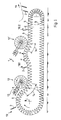
- the device 1 schematically shows a device 1 according to the invention for a plug-in collection of printed products 2 for printed products 3.
- the device 1 has a conveyor 4 from two endless conveyor chains running side by side 5, which extends transversely to the conveying direction F, pocket-like receptacle 6 are connected. Latter are formed at their upper end through a loading opening and start in the illustrated embodiment one end on a deflection wheel 7 about an axis 8.
- a deflection wheel 9 provided with a smaller diameter.
- One of the two Deflection wheels 7, 9 can be used as the drive wheel of the conveyor 4 be formed. Run between the deflection wheels 7, 9 the conveyor chains 5 in lateral guide rails, the are not shown in Fig. 1.
- the upper run of the revolving Conveyor chains 5 form a conveyor line that runs from the first Feed station 10 for a main product 2 to a removal station 11 is enough for the printed product 3.
- On the conveyor line further feed stations 10.1 and 10.2 are provided, which are indicated by an arrow.
- On the funding route of the printed products 2 are in the downstream distance to the Feeding stations 10, 10.1, 10.2, which are designed as so-called feeders are, opening devices 12, 12 'arranged, the open printed products 2 inserted into the receptacle 6. This opening process takes place during the transport of the Print products 2 and not in cooperation with the deflection wheel 7.
- Fig. 1 further conveys that the opening device 12 removable from the processing area when not in use is.
- the opening device 12 is on, for example attached a pivotable arm 13.
- a illustrated as a rotor opening device 12 whose opening effective scope with a conveyor 4 running in the same direction, a common about sectoral opening section 14, respectively. an opening route forms.
- a further feed station 10.1 is provided on the conveyor line, through which a so-called.
- Preproduct 2 folds ahead into that in a receiving container 6 inserted past main product 2 inserted becomes.
- a further preliminary product or To be able to insert a supplement by insert follows one Conveying section another opening device 12. So a common opening section arises, the runs Conveyor 4 in front of the opening device 12 is humped rising in a then sinking Course on the circumference of the further opening device 12.
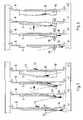
- FIG. 2 shows the course of the conveyor 4 and the opposite Opening device 12 to the opening area.
- the rotor respectively.
- the conveyor 4 arranged opening device 12 points to the free edge area of one in a receptacle 6 existing print product 2 acting Opening means.
- These essentially include: Gripping member 15, a separating member 16 which when performing its function can be supported by a support member 17.
- the Figure 2 shows the inserted printed products 2 on the Opening section through opening sequences. That one Receiving container 6 of the conveying device 4 supplied printed product 2 reaches the opening section in the closed state or the opening distance it is continuous passes.
- this is recorded as a suction device trained gripping member 15 on the printed product 2 the rear side in the conveying direction in the upper edge area, also called flower. So that in this process the upper one Edge area of the printed product 2 cannot dodge, an deliverable support member 17 is provided which before Printed product 2, positioned opposite the suction head 18 and so reliable detection of the rear Leg of the printed product 2 by the suction gripping member 15 guaranteed.
- an deliverable support member 17 is provided which before Printed product 2, positioned opposite the suction head 18 and so reliable detection of the rear Leg of the printed product 2 by the suction gripping member 15 guaranteed.
- the separator 16 between the leg of the printed product 2 executes an additional movement against the conveying direction F, the suction device respectively. Gripping device 15 from rear leg of the printed product released and in the starting position set back.
- the support member 17 also has reached its starting position removed from printed product 2 again. After the withdrawal of the support member 17, the front Leg of the printed product 2 at the top free edge of one Gripper 19 pressed against the front inner wall of the receptacle. As a result, the printed product is locked at least on one side and the opening process can be performed by the separating element 16 be ended.
- the printed product 2 is now open on the Fold in the receptacle 6 and can with a printed product respectively. Intermediate product 2 are loaded. In the sense of a favor the reliability of the opening process could be the front of the printed product 2 attacking area of the Support member 17 can be designed as a suction element.
- Fig. 3 illustrates the opening device 12 in cooperation with the conveyor 4 connected to conveyor chains 5 is suspended in lateral guideways 21.
- the opening device 12 has a hub 22 on which the mentioned Opening means 15, 16, 17 are arranged.
- the hub 22 in turn is on one along the axis of rotation 23 of the opening device 12 slidable sleeve 24 stored.
- the axis of rotation 23 in turn, through a transverse to the conveying direction F on one Frame 25 of the device 1 attached guide rod 26 is formed.
- a bracket 28 is fastened to which a hub 22 drive-connected motor 29 is screwed.
- the drive connection is done by a gear train 30, a gear on the motor shaft with a ring gear the hub 22 combs.
- the hub 22 is adjacent to the ring gear Storage devices 31, 32 for the deliverable separator 16 and support members 17.
- these Storage devices 31, 32 in which the lever-shaped Separating 16 and support members 17 are pivotally mounted, are the bearing devices 31, 32 for changing the mutual Distance adjustable. This arrangement is shown in Fig. 4, where the support member 17 directly is pivotable on the hub 22, while the separating member 16 and the gripping member 15 on one with respect to the support member 17 on the circumference the hub 22 rotatable bearing device 32 is arranged are.
- the support member 17 could also be opposite Partition 16 and gripping member 15 for the purpose of changing the distance be adjustable.
- Partition 16 and support member 17 have for actuation concentrically to the pivot axis 48 in each case a gear 33, 34 which mesh with a rack 35, 36.
- the racks 35, 36 which are longitudinally guided in the hub 22 are formed at one end with a control roller 37, 38, each to drive separator 16 and support member 17 in one order the axis of rotation 23 of the fixed control cam 37, 38 extends, such that the drive movements of the racks 35, 36 of Separating 16 and support member 17 directed approximately parallel to the axis of rotation 23 are.
- the control curves 37, 38 are with the sleeve 24 firmly connected, for which purpose a flange 39 on the sleeve 24 is provided.
- the hub 22 is formed in two parts, i.e. with a drive part 40 and an adjustment part 41, which rotate together, but are mutually rotatable.
- Separating 16 and support member 17 move viewed in plan view at a flat angle ⁇ or ⁇ to the transverse extent the receptacle 6, these angles mutually diverge.
- the support member 17 pivots in front of the separating member 16 from the rest position above the conveyor 4 through a recess 42 in the receptacle 6 into a upper side area of the printed product 2, on the front and lifts it from the inner wall of the receptacle 6 to then swivel in from the opposite direction Separator 16 to be opened (see also Fig. 5).
- the printed product part captured by the separating member 16 becomes so laid on the trailing inner wall of the receptacle 6 and by means of the front printed product part in the conveying direction Gripper 19 held on the receptacle 6 (see Fig. 2).
- the sequences designated a) to d) in FIG. 5 keep this process as already illustrated in Fig. 3 firmly.
- the trailing printed product part can be a Print product 2 are raised by means of suction head 18 and the Printed product parts can be swung in by the Separator 16 are separated from each other.
- the Separator 16 is separated from each other.
Landscapes
- Engineering & Computer Science (AREA)
- Mechanical Engineering (AREA)
- Inspection Of Paper Currency And Valuable Securities (AREA)
- Collation Of Sheets And Webs (AREA)
- Supplying Of Containers To The Packaging Station (AREA)
- Folding Of Thin Sheet-Like Materials, Special Discharging Devices, And Others (AREA)
- Sheets, Magazines, And Separation Thereof (AREA)
- Electric Connection Of Electric Components To Printed Circuits (AREA)
- Separation, Sorting, Adjustment, Or Bending Of Sheets To Be Conveyed (AREA)
- Auxiliary Devices For And Details Of Packaging Control (AREA)
- Specific Conveyance Elements (AREA)
Abstract
Description
Die Erfindung betrifft eine Einrichtung zum einsteckweisen Sammeln von Druckprodukten in an einer um zwei voneinander distanzierten Umlenkrädern umlaufenden Fördereinrichtung hintereinander geführten, quer zur Förderrichtung sich erstreckenden und am oberen Ende eine Beschickungsöffnung aufweisenden, taschenähnlichen Aufnahmebehältern, die zwischen einer Zuführstation für Druckprodukte und einer Entnahmestation der eingesteckten Druckprodukte eine die durch eine Beschickungsvorrichtung falzvoran zugeführten Druckprodukte öffnende, stationäre Oeffnungsvorrichtung aufweist.The invention relates to a device for inserting Collect print products in one at a time from each other distant deflection wheels rotating conveyor in a row guided, extending transversely to the conveying direction and a loading opening at the upper end, pocket-like receptacles that are between a Feed station for printed products and a removal station of the inserted printed products a through a loading device Stationary printed products that are opening in front of the fold Has opening device.
Einrichtungen dieser Art werden auch als Einsteckmaschinen bezeichnet und werden in erster Linie in der Zeitungsproduktion eingesetzt.Devices of this type are also known as inserting machines and are primarily used in newspaper production used.
Bei einer gattungsgleichen Einrichtung gemäss EP 0 336 062 B1
ist eine Oeffnungsvorrichtung seitlich an einem umlaufend angetriebenen
Zwillingskettenrad wirkend, nach einer Hauptprodukteinlegestation
vorgesehen.
Bei dieser Anordnungsweise können sich die zum Oeffnen zugeführten
Druckprodukte aufgrund der kurzen Wegstrecke bis zur
Oeffnungsvorrichtung nicht beruhigen, sodass der Oeffnungsvorgang
nicht zuverlässig durchführbar ist.In the case of a device of the same type according to EP 0 336 062 B1, an opening device is provided which acts laterally on a rotatingly driven twin sprocket after a main product insertion station.
With this arrangement, the printed products supplied for opening cannot settle due to the short distance to the opening device, so that the opening process cannot be carried out reliably.
Weiterhin ist diese Ausführungsform zum Oeffnen von Druckprodukten nur im Zusammenwirken mit einem Antriebs- oder Umlenkrad möglich und bei mehreren Oeffnungsstationen entlang einer Fördereinrichtung mit hohen Kosten verbunden.Furthermore, this embodiment is for opening printed products only in conjunction with a drive or deflection wheel possible and with several opening stations along one Conveyor device associated with high costs.
Aufgabe der vorliegenden Erfindung ist es nun, eine Einrichtung zu schaffen, mit der die erwähnten Nachteile behoben werden und die den Ansprüchen einer neuzeitlichen Verarbeitung genügen.The object of the present invention is now a device to create, with which the disadvantages mentioned are eliminated and the demands of modern processing suffice.
Erfindungsgemäss wird die Aufgabe dadurch gelöst, dass die Oeffnungsvorrichtung in Förderrichtung betrachtet dem ersten Umlenkrad nachgeschaltet ist.According to the invention the object is achieved in that the Opening device in the direction of conveyance considered the first Deflection wheel is connected.
Anschliessend wird die Erfindung unter Bezugnahme auf die Zeichnung, auf die bezüglich aller in der Beschreibung nicht näher erwähnten Einzelheiten verwiesen wird, anhand eines Ausführungsbeispiels erläutert. In der Zeichnung zeigen:
- Fig. 1
- eine schematische Darstellung der erfindungsgemässen Einrichtung,
- Fig. 2
- einen Ausschnitt aus der Darstellung in Fig. 1,
- Fig. 3
- einen Schnitt durch die Einrichtung gemäss der Linie III - III in Fig. 2,
- Fig. 4
- einen Schnitt durch die Einrichtung nach der Linie IV - IV in Fig. 3,
- Fig. 5
- eine ausschnittweise Draufsicht auf die Fördereinrichtung im Oeffnungsbereich und
- Fig. 6
- eine ausschnittweise Draufsicht auf die Fördereinrichtung in einem alternativ ausgestalteten Oeffnungsbereich.
- Fig. 1
- 1 shows a schematic representation of the device according to the invention,
- Fig. 2
- 1 shows a section of the illustration in FIG. 1,
- Fig. 3
- 3 shows a section through the device according to line III-III in FIG. 2,
- Fig. 4
- 3 shows a section through the device according to line IV-IV in FIG. 3,
- Fig. 5
- a partial plan view of the conveyor in the opening area and
- Fig. 6
- a partial plan view of the conveyor in an alternatively designed opening area.
Fig. 1 zeigt schematisch eine erfindungsgemässe Einrichtung 1
für ein einsteckweises Sammeln von Druckprodukten 2 zu Druckerzeugnissen
3. Die Einrichtung 1 weist eine Fördereinrichtung
4 aus zwei nebeneinander geführten, endlosen Förderketten
5 auf, die durch quer zur Förderrichtung F sich erstreckende,
taschenähnliche Aufnahmebehälter 6 verbunden sind. Letztere
sind an ihrem oberen Ende durch eine Beschickungsöffnung ausgebildet
und laufen beim dargestellten Ausführungsbeispiel an
dem einen Ende an einem Umlenkrad 7 um eine Achse 8 um. An dem
gegenüberliegenden Förderende der Einrichtung 1 ist ein Umlenkrad
9 mit kleinerem Durchmesser vorgesehen. Eines der beiden
Umlenkräder 7, 9 kann als Antriebsrad der Fördereinrichtung
4 ausgebildet sein. Zwischen den Umlenkrädern 7, 9 verlaufen
die Förderketten 5 in seitlichen Führungsschienen, die
in Fig. 1 nicht dargestellt sind. Der obere Trum der umlaufenden
Förderketten 5 bildet eine Förderstrecke, die von der ersten
Zuführstation 10 für ein Hauptprodukt 2 bis an eine Entnahmestation
11 für das Druckerzeugnis 3 reicht. An der Förderstrecke
sind weitere Zuführstationen 10.1 und 10.2 vorgesehen,
die durch einen Pfeil angedeutet sind. Auf dem Förderweg
der Druckprodukte 2 sind im nachgeschalteten Abstand zu den
Zuführstationen 10, 10.1, 10.2, die als sog. Anleger ausgebildet
sind, Oeffnungsvorrichtungen 12, 12' angeordnet, die die
in die Aufnahmebehälter 6 eingesteckten Druckprodukte 2 öffnen.
Dieser Oeffnungsvorgang erfolgt während dem Transport der
Druckprodukte 2 und nicht im Zusammenwirken mit dem Umlenkrad
7. Die Fig. 1 vermittelt weiter, dass die Oeffnungsvorrichtung
12 bei Nichtgebrauch aus dem Verarbeitungsbereich entfernbar
ist. Hierzu ist die Oeffnungsvorrichtung 12 beispielsweise an
einem hochschwenkbaren Arm 13 befestigt. Beim vorliegenden
Ausführungsbeispiel ist in Förderrichtung anschliessend an das
Umlenkrad 7, an dem ein Hauptprodukt 2 zugeführt wird, eine
als Rotor ausgebildete Oeffnungsvorrichtung 12 veranschaulicht,
deren öffnungswirksamer Umfang mit einem mit der
gleichsinnig verlaufenden Fördereinrichtung 4 einen gemeinsamen,
etwa sektoriellen Oeffnungsabschnitt 14 resp. eine Oeffnungsstrecke
bildet. Nach der Oeffnungsvorrichtung 12 ist an
der Förderstrecke eine weitere Zuführstation 10.1 vorgesehen,
durch die ein sog. Vorprodukt 2 falzvoran in das in einem Aufnahmebehälter
6 geöffnet vorbeigeführte Hauptprodukt 2 eingesteckt
wird. Um dem Vorprodukt 2 ein weiteres Vorprodukt oder
eine Beilage einsteckweise zuführen zu können, folgt nach einem
Förderabschnitt eine weitere Oeffnungsvorrichtung 12. Damit
ein gemeinsamer Oeffnungsabschnitt entsteht, verläuft die
Fördereinrichtung 4 vor der Oeffnungsvorrichtung 12 sich buckelförmig
erhebend in einem sich anschliessend absenkenden
Verlauf an den Umfang der weiteren Oeffnungsvorrichtung 12. 1 schematically shows a device 1 according to the invention
for a plug-in collection of printed
In den Fig. 2 und 3 ist das Zusammenwirken von Fördereinrichtung
4 und Oeffnungsvorrichtung 12 detailliert festgehalten.
Fig. 2 zeigt den Verlauf der Fördereinrichtung 4 und die gegenüberliegende
Oeffnungsvorrichtung 12 zum Oeffnungsbereich.
Die als Rotor resp. Trommel ausgebildete und über der Förderstrecke
der Fördereinrichtung 4 angeordnete Oeffnungsvorrichtung
12 weist auf den freien Randbereich eines in einem Aufnahmebehälter
6 sich befindenden Druckproduktes 2 einwirkende
Oeffnungsmittel auf. Zu diesen gehören im wesentlichen ein
Greiforgan 15, ein Trennorgan 16, die bei Ausübung ihrer Funktion
von einem Stützorgan 17 unterstützt werden können. Die
Figur 2 zeigt von den eingesteckten Druckprodukten 2 auf dem
Oeffnungsabschnitt durchlaufene Oeffnungssequenzen. Das einem
Aufnahmebehälter 6 der Fördereinrichtung 4 zugeführte Druckprodukt
2 erreicht in geschlossenem Zustand den Oeffnungsabschnitt
bzw. die Oeffnungsstrecke, die es kontinuierlich
durchläuft. In einem ersten Schritt erfasst das hier als Saugvorrichtung
ausgebildete Greiforgan 15 das Druckprodukt 2 an
der in Förderrichtung rückwärtigen Seite im oberen Randbereich,
auch Blume bezeichnet. Damit bei diesem Vorgang der obere
Randbereich des Druckproduktes 2 nicht ausweichen kann,
ist ein zustellbares Stützorgan 17 vorgesehen, das vor dem
Druckprodukt 2, gegenüberliegend von dem Saugkopf 18 positioniert
wird und so ein zuverlässiges Erfassen des hinteren
Schenkels des Druckproduktes 2 durch das saugende Greiforgan
15 gewährleistet. Durch eine Schwenkbewegung des Greiforgans
15 in eine zur Förderrichtung F entgegengesetzte Richtung werden
die Schenkel des Druckproduktes 2 voneinandergetrennt und
ein Trennorgan 16 der Oeffnungsvorrichtung 12 fährt in das geöffnete
Druckprodukt 2 ein. Sobald das Trennorgan 16 zwischen
die Schenkel des Druckproduktes 2 eingetaucht ist, indem es
eine zusätzliche Bewegung entgegen der Förderrichtung F ausführt,
wird die Saugvorrichtung resp. Greifvorrichtung 15 vom
hinteren Schenkel des Druckproduktes gelöst und in die Ausgangslage
zurückversetzt. Auch das benützte Stützorgan 17 hat
seine von Druckprodukt 2 entfernte Ausgangsposition wieder erreicht.
Nach dem Rückzug des Stützorgans 17 wird der vordere
Schenkel des Druckproduktes 2 am oberen freien Rand von einem
Greifer 19 an die vordere Innenwand des Aufnahmebehälters gepresst.
Dadurch ist das Druckprodukt wenigstens einseitig arretiert
und der Oeffnungsvorgang kann durch das Trennorgan 16
beendet werden. Das Druckprodukt 2 steht nun geöffnet auf dem
Falz im Aufnahmebehälter 6 und kann mit einem Druckprodukt
resp. Vorprodukt 2 beschickt werden. Im Sinne einer Begünstigung
der Zuverlässigkeit beim Oeffnungsvorgang könnte der an
der Vorderseite des Druckproduktes 2 angreifende Bereich des
Stützorgans 17 als Saugelement ausgebildet sein.2 and 3 is the interaction of the
Fig. 3 veranschaulicht die Oeffnungsvorrichtung 12 im Zusammenwirken
mit der Fördereinrichtung 4, die an Förderketten 5
in seitlichen Führungsbahnen 21 aufgehängt ist. Die Oeffnungsvorrichtung
12 weist eine Nabe 22 auf, an der die erwähnten
Oeffnungsmittel 15, 16, 17 angeordnet sind. Die Nabe 22 ihrerseits
ist an einer entlang der Drehachse 23 der Oeffnungsvorrichtung
12 verschiebbaren Muffe 24 gelagert. Die Drehachse 23
wiederum wird durch eine quer zur Förderrichtung F an einem
Gestell 25 der Einrichtung 1 befestigte Führungsstange 26 gebildet.
An der auf Achsiallagern 27 formatverstellbaren Muffe
24 ist eine Konsole 28 befestigt, an der ein mit der Nabe 22
antriebsverbundener Motor 29 festgeschraubt ist. Die Antriebsverbindung
erfolgt durch ein Zahnradvorgelege 30, wobei ein
auf der Motorwelle sitzendes Zahnrad mit einem Zahnkranz an
der Nabe 22 kämmt. Benachbart zum Zahnkranz weist die Nabe 22
am Umfang verteilt angeordnete Lagervorrichtungen 31, 32 für
die zustellbaren Trenn- 16 und Stützorgane 17 auf. Von diesen
Lagervorrichtungen 31, 32, in denen die hebelartig ausgebildeten
Trenn- 16 und Stützorgane 17 schwenkbar gelagert sind,
sind die Lagervorrichtungen 31, 32 zur Aenderung des gegenseitigen
Abstandes verstellbar ausgebildet. Diese Anordnungsweise
ist in Fig. 4 dargestellt, wobei dort das Stützorgan 17 direkt
an der Nabe 22 schwenkbar ist, während das Trennorgan 16 und
das Greiforgan 15 an einer gegenüber dem Stützorgan 17 am Umfang
der Nabe 22 verdrehbaren Lagervorrichtung 32 angeordnet
sind.Fig. 3 illustrates the
Selbstverständlich könnte auch das Stützorgan 17 gegenüber
Trenn- 16 und Greiforgan 15 zwecks Aenderung des Abstandes
verstellbar ausgebildet sein. Trenn- 16 und Stützorgan 17 weisen
zur Betätigung konzentrisch zur Schwenkachse 48 jeweils
ein Zahnrad 33, 34 auf, die mit einer Zahnstange 35, 36 kämmen.
Die in der Nabe 22 längsgeführten Zahnstangen 35, 36 sind
einenends mit einer Steuerrolle 37, 38 ausgebildet, die jeweils
zum Antrieb von Trenn- 16 und Stützorgan 17 in einer um
die Drehachse 23 fest angeordnete Steuerkurve 37, 38 verläuft,
derart, dass die Antriebsbewegungen der Zahnstangen 35, 36 von
Trenn- 16 und Stützorgan 17 etwa parallel zur Drehachse 23 gerichtet
sind. Die Steuerkurven 37, 38 sind mit der Muffe 24
fest verbunden, wozu endseitig ein Flansch 39 an der Muffe 24
vorgesehen ist. Zur gegenseitigen Veränderung des Abstandes
zwischen einem Trenn- 16 und einem diesen zugeordneten Stützorgan
17, die in Drehrichtung hintereinander angeordnet sind,
ist die Nabe 22 zweiteilig ausgebildet, d.h. mit einem Antriebsteil
40 und einem Verstellteil 41, die gemeinsam umlaufen,
jedoch gegenseitig verdrehbar sind. Of course, the
Trenn- 16 und Stützorgan 17 bewegen sich in Draufsicht betrachtet
in einem flachen Winkel β bzw. α zu der Quererstreckung
der Aufnahmebehälter 6, wobei diese Winkel gegenseitig
divergieren. Dabei schwenkt das Stützorgan 17 vor dem Trennorgan
16 aus der Ruhestellung oberhalb der Fördereinrichtung 4
durch eine Ausnehmung 42 in dem Aufnahmebehälter 6 in einen
oberen Seitenbereich des Druckproduktes 2, an dessen Vorderseite
und hebt es von der Innenwand des Aufnahmebehälters 6
ab, um anschliessend von dem aus der Gegenrichtung einschwenkenden
Trennorgan 16 geöffnet zu werden (siehe hierzu auch
Fig. 5). Der vom Trennorgan 16 erfasste Druckprodukteteil wird
so an die nachlaufende Innenwand des Aufnahmebehälters 6 verlegt
und der in Förderrichtung vordere Druckprodukteteil mittels
Greifer 19 an dem Aufnahmebehälter 6 festgehalten (siehe
Fig. 2). Die mit a) bis d) bezeichneten Sequenzen in Fig. 5
halten diesen Vorgang wie schon in Fig. 3 veranschaulicht
fest.Separating 16 and
Bei Verwendung eines zusätzlichen pneumatischen Greiforgans
15, das an einem mit dem Verstellteil 41 der Nabe 22 verbundenen
Ausleger 43 schwenkbar gelagert ist, verläuft eine an einem
mit einer schwenkbaren Welle 44 verbundenen Hebel 45 frei
drehbar befestigte Rolle 46 in einer Steuerbahn 47, die am Umfang
des Flansches 39 angeordnet ist.When using an additional
Gemäss Fig. 6 kann der nachlaufende Druckprodukteteil eines
Druckproduktes 2 mittels Saugkopf 18 angehoben werden und die
Druckprodukteteile können durch das anschliessend einschwenkende
Trennorgan 16 von einander getrennt werden. Anstelle eines
Stützorgans 17, wie in Fig. 5, übernimmt beim Vorgang nach
Fig. 6 die vordere Wand eines Aufnahmebehälters 6 die rückwärtige
Stützfunktion.6, the trailing printed product part can be a
Claims (19)
Priority Applications (7)
| Application Number | Priority Date | Filing Date | Title |
|---|---|---|---|
| AT01811077T ATE299831T1 (en) | 2001-11-08 | 2001-11-08 | DEVICE FOR COLLECTING PRINT PRODUCTS BY POCKET |
| EP01811077A EP1310444B1 (en) | 2001-11-08 | 2001-11-08 | Device for collecting print products by insertion |
| DE50106806T DE50106806D1 (en) | 2001-11-08 | 2001-11-08 | Device for the pick-up collection of printed products |
| DK01811077T DK1310444T3 (en) | 2001-11-08 | 2001-11-08 | Device for assembling print products by insertion |
| AU2002301060A AU2002301060B2 (en) | 2001-11-08 | 2002-09-17 | Device to assemble printed products by insertion |
| US10/287,699 US6820870B2 (en) | 2001-11-08 | 2002-11-05 | Device for opening and inserting printed products in a gathering line |
| NO20025338A NO323729B1 (en) | 2001-11-08 | 2002-11-07 | Device for collecting printed matter by insertion |
Applications Claiming Priority (1)
| Application Number | Priority Date | Filing Date | Title |
|---|---|---|---|
| EP01811077A EP1310444B1 (en) | 2001-11-08 | 2001-11-08 | Device for collecting print products by insertion |
Publications (2)
| Publication Number | Publication Date |
|---|---|
| EP1310444A1 true EP1310444A1 (en) | 2003-05-14 |
| EP1310444B1 EP1310444B1 (en) | 2005-07-20 |
Family
ID=8184229
Family Applications (1)
| Application Number | Title | Priority Date | Filing Date |
|---|---|---|---|
| EP01811077A Expired - Lifetime EP1310444B1 (en) | 2001-11-08 | 2001-11-08 | Device for collecting print products by insertion |
Country Status (7)
| Country | Link |
|---|---|
| US (1) | US6820870B2 (en) |
| EP (1) | EP1310444B1 (en) |
| AT (1) | ATE299831T1 (en) |
| AU (1) | AU2002301060B2 (en) |
| DE (1) | DE50106806D1 (en) |
| DK (1) | DK1310444T3 (en) |
| NO (1) | NO323729B1 (en) |
Cited By (3)
| Publication number | Priority date | Publication date | Assignee | Title |
|---|---|---|---|---|
| CH706457A1 (en) * | 2012-04-30 | 2013-10-31 | Ferag Ag | Method and apparatus for the insertion of objects into folded printed products. |
| WO2016044959A1 (en) * | 2014-09-25 | 2016-03-31 | Ferag Ag | Apparatus and method for separating product parts of a multipart product |
| EP1588971B2 (en) † | 2004-04-22 | 2019-06-19 | Ferag AG | Method and apparatus for handling of printed products |
Families Citing this family (3)
| Publication number | Priority date | Publication date | Assignee | Title |
|---|---|---|---|---|
| EP1657199B1 (en) * | 2004-11-12 | 2008-07-09 | Müller Martini Holding AG | Apparatus for handling of flat products, in particular print products |
| DE502006006239D1 (en) * | 2006-06-01 | 2010-04-08 | Mueller Martini Holding Ag | Device for processing printed products |
| CH701214A1 (en) * | 2009-06-03 | 2010-12-15 | Ferag Ag | Apparatus and method for processing printed products. |
Citations (3)
| Publication number | Priority date | Publication date | Assignee | Title |
|---|---|---|---|---|
| US4723770A (en) * | 1986-06-20 | 1988-02-09 | Graphic Management Associates, Inc. | Straight-line insert machine |
| EP0336062B1 (en) * | 1988-03-31 | 1992-03-18 | Grapha-Holding Ag | Insertion machine |
| EP0498935A1 (en) * | 1991-02-13 | 1992-08-19 | Graphic Management Associates, Inc. | Non-lap opener |
Family Cites Families (5)
| Publication number | Priority date | Publication date | Assignee | Title |
|---|---|---|---|---|
| US4046367A (en) * | 1975-11-10 | 1977-09-06 | American Newspaper Publishers Association, Incorporated | Modified high speed paper inserting apparatus and method |
| US5269504A (en) * | 1989-06-10 | 1993-12-14 | Idab Wamac Ab | Insertion of supplements into newspapers |
| US5112036A (en) * | 1990-08-27 | 1992-05-12 | Graphic Management Associates, Inc. | Opener for folder printed products |
| CH696637A5 (en) * | 1997-01-31 | 2007-08-31 | Ferag Ag | A method of inserting printed products into a folded main product. |
| EP0911289B2 (en) * | 1997-10-27 | 2007-03-21 | Grapha-Holding Ag | Method of producing printed documents by inserting components and/or inserts in a main product and device for carring out the method |
-
2001
- 2001-11-08 EP EP01811077A patent/EP1310444B1/en not_active Expired - Lifetime
- 2001-11-08 DE DE50106806T patent/DE50106806D1/en not_active Expired - Lifetime
- 2001-11-08 AT AT01811077T patent/ATE299831T1/en not_active IP Right Cessation
- 2001-11-08 DK DK01811077T patent/DK1310444T3/en active
-
2002
- 2002-09-17 AU AU2002301060A patent/AU2002301060B2/en not_active Ceased
- 2002-11-05 US US10/287,699 patent/US6820870B2/en not_active Expired - Fee Related
- 2002-11-07 NO NO20025338A patent/NO323729B1/en not_active IP Right Cessation
Patent Citations (3)
| Publication number | Priority date | Publication date | Assignee | Title |
|---|---|---|---|---|
| US4723770A (en) * | 1986-06-20 | 1988-02-09 | Graphic Management Associates, Inc. | Straight-line insert machine |
| EP0336062B1 (en) * | 1988-03-31 | 1992-03-18 | Grapha-Holding Ag | Insertion machine |
| EP0498935A1 (en) * | 1991-02-13 | 1992-08-19 | Graphic Management Associates, Inc. | Non-lap opener |
Cited By (3)
| Publication number | Priority date | Publication date | Assignee | Title |
|---|---|---|---|---|
| EP1588971B2 (en) † | 2004-04-22 | 2019-06-19 | Ferag AG | Method and apparatus for handling of printed products |
| CH706457A1 (en) * | 2012-04-30 | 2013-10-31 | Ferag Ag | Method and apparatus for the insertion of objects into folded printed products. |
| WO2016044959A1 (en) * | 2014-09-25 | 2016-03-31 | Ferag Ag | Apparatus and method for separating product parts of a multipart product |
Also Published As
| Publication number | Publication date |
|---|---|
| NO20025338D0 (en) | 2002-11-07 |
| US6820870B2 (en) | 2004-11-23 |
| ATE299831T1 (en) | 2005-08-15 |
| US20030085503A1 (en) | 2003-05-08 |
| DK1310444T3 (en) | 2005-10-31 |
| AU2002301060B2 (en) | 2010-01-28 |
| EP1310444B1 (en) | 2005-07-20 |
| DE50106806D1 (en) | 2005-08-25 |
| NO323729B1 (en) | 2007-07-02 |
| NO20025338L (en) | 2003-05-09 |
Similar Documents
| Publication | Publication Date | Title |
|---|---|---|
| DE3348034C2 (en) | ||
| EP0346578B1 (en) | Device for assembling, collating and inserting printing products | |
| DE3620945C5 (en) | Device for collecting folded printed sheets | |
| EP0208081B1 (en) | Method and device for opening eccentrically folded printing products | |
| DE2037006C3 (en) | Device for feeding and inserting rod-shaped or tubular winding cores of a support roller winding machine when changing laps | |
| EP0606550B1 (en) | Device for bringing flat products to a processing device for printed products | |
| DE2366378C2 (en) | Transfer device for the transfer of separated, aligned workpieces | |
| EP0529689B1 (en) | Device for transferring parallelepipedic packages | |
| DE102015108391A1 (en) | Device for transporting a container | |
| EP0251032A2 (en) | Packing or unpacking machine | |
| EP0218949B1 (en) | Method and apparatus for feeding conical bobbin tubes to a textile machine | |
| AT396908B (en) | DEVICE FOR PROCESSING PRINTED PRODUCTS | |
| EP1055620B1 (en) | Device for picking up and/or transporting flexible and flat products | |
| DE19916668A1 (en) | Conveyor for flat pieces comprises parallel conveyor belts running over deflection wheels, clamping elements, pick-up pieces and swivel axle | |
| EP1351873B1 (en) | Device for processing printing products | |
| EP0210494B1 (en) | Collecting device for folded printed sheets | |
| EP1310444A1 (en) | Device for collecting print products by insertion | |
| EP0967164B1 (en) | Method and device for feeding folded printed sheets astride on a gathering section | |
| EP2782836A1 (en) | Method and device for handling bags combined into bundles | |
| DE102017104266B4 (en) | Device for transporting elongated pieces to a receiving location and for depositing it at this location | |
| EP1016606B1 (en) | Feeder | |
| DE2530698B2 (en) | Method and device for the jam-free transfer of soap bars or the like that are mainly supplied at unequal distances | |
| DE2924407C2 (en) | Device for the continuous wrapping of sweets or similar small parts | |
| DE2415166B2 (en) | DEVICE FOR ALIGNING CONICAL SPOOL CASES AND FOR TRANSFERRING THE ALIGNED SPOOL CASES TO THE FEEDING DEVICE OF A SPINNING MACHINE O.DGL. | |
| DE10124712C2 (en) | Device for inserting sausages into a packaging |
Legal Events
| Date | Code | Title | Description |
|---|---|---|---|
| PUAI | Public reference made under article 153(3) epc to a published international application that has entered the european phase |
Free format text: ORIGINAL CODE: 0009012 |
|
| AK | Designated contracting states |
Designated state(s): AT BE CH CY DE DK ES FI FR GB GR IE IT LI LU MC NL PT SE TR |
|
| AX | Request for extension of the european patent |
Extension state: AL LT LV MK RO SI |
|
| 17P | Request for examination filed |
Effective date: 20030905 |
|
| 17Q | First examination report despatched |
Effective date: 20031211 |
|
| AKX | Designation fees paid |
Designated state(s): AT BE CH CY DE DK ES FI FR GB GR IE IT LI LU MC NL PT SE TR |
|
| GRAP | Despatch of communication of intention to grant a patent |
Free format text: ORIGINAL CODE: EPIDOSNIGR1 |
|
| GRAS | Grant fee paid |
Free format text: ORIGINAL CODE: EPIDOSNIGR3 |
|
| GRAA | (expected) grant |
Free format text: ORIGINAL CODE: 0009210 |
|
| AK | Designated contracting states |
Kind code of ref document: B1 Designated state(s): AT BE CH CY DE DK ES FI FR GB GR IE IT LI LU MC NL PT SE TR |
|
| PG25 | Lapsed in a contracting state [announced via postgrant information from national office to epo] |
Ref country code: TR Free format text: LAPSE BECAUSE OF FAILURE TO SUBMIT A TRANSLATION OF THE DESCRIPTION OR TO PAY THE FEE WITHIN THE PRESCRIBED TIME-LIMIT Effective date: 20050720 Ref country code: NL Free format text: LAPSE BECAUSE OF FAILURE TO SUBMIT A TRANSLATION OF THE DESCRIPTION OR TO PAY THE FEE WITHIN THE PRESCRIBED TIME-LIMIT Effective date: 20050720 Ref country code: ES Free format text: LAPSE BECAUSE OF FAILURE TO SUBMIT A TRANSLATION OF THE DESCRIPTION OR TO PAY THE FEE WITHIN THE PRESCRIBED TIME-LIMIT Effective date: 20050720 Ref country code: IE Free format text: LAPSE BECAUSE OF FAILURE TO SUBMIT A TRANSLATION OF THE DESCRIPTION OR TO PAY THE FEE WITHIN THE PRESCRIBED TIME-LIMIT Effective date: 20050720 Ref country code: FI Free format text: LAPSE BECAUSE OF FAILURE TO SUBMIT A TRANSLATION OF THE DESCRIPTION OR TO PAY THE FEE WITHIN THE PRESCRIBED TIME-LIMIT Effective date: 20050720 |
|
| REG | Reference to a national code |
Ref country code: GB Ref legal event code: FG4D Free format text: NOT ENGLISH |
|
| REG | Reference to a national code |
Ref country code: CH Ref legal event code: EP |
|
| REG | Reference to a national code |
Ref country code: IE Ref legal event code: FG4D Free format text: LANGUAGE OF EP DOCUMENT: GERMAN |
|
| REF | Corresponds to: |
Ref document number: 50106806 Country of ref document: DE Date of ref document: 20050825 Kind code of ref document: P |
|
| GBT | Gb: translation of ep patent filed (gb section 77(6)(a)/1977) |
Effective date: 20050912 |
|
| REG | Reference to a national code |
Ref country code: SE Ref legal event code: TRGR |
|
| PG25 | Lapsed in a contracting state [announced via postgrant information from national office to epo] |
Ref country code: GR Free format text: LAPSE BECAUSE OF FAILURE TO SUBMIT A TRANSLATION OF THE DESCRIPTION OR TO PAY THE FEE WITHIN THE PRESCRIBED TIME-LIMIT Effective date: 20051020 |
|
| REG | Reference to a national code |
Ref country code: DK Ref legal event code: T3 |
|
| PG25 | Lapsed in a contracting state [announced via postgrant information from national office to epo] |
Ref country code: AT Free format text: LAPSE BECAUSE OF NON-PAYMENT OF DUE FEES Effective date: 20051108 Ref country code: CY Free format text: LAPSE BECAUSE OF FAILURE TO SUBMIT A TRANSLATION OF THE DESCRIPTION OR TO PAY THE FEE WITHIN THE PRESCRIBED TIME-LIMIT Effective date: 20051108 |
|
| PG25 | Lapsed in a contracting state [announced via postgrant information from national office to epo] |
Ref country code: LU Free format text: LAPSE BECAUSE OF NON-PAYMENT OF DUE FEES Effective date: 20051130 Ref country code: MC Free format text: LAPSE BECAUSE OF NON-PAYMENT OF DUE FEES Effective date: 20051130 Ref country code: BE Free format text: LAPSE BECAUSE OF NON-PAYMENT OF DUE FEES Effective date: 20051130 |
|
| PG25 | Lapsed in a contracting state [announced via postgrant information from national office to epo] |
Ref country code: PT Free format text: LAPSE BECAUSE OF FAILURE TO SUBMIT A TRANSLATION OF THE DESCRIPTION OR TO PAY THE FEE WITHIN THE PRESCRIBED TIME-LIMIT Effective date: 20051221 |
|
| NLV1 | Nl: lapsed or annulled due to failure to fulfill the requirements of art. 29p and 29m of the patents act | ||
| REG | Reference to a national code |
Ref country code: IE Ref legal event code: FD4D |
|
| ET | Fr: translation filed | ||
| PLBE | No opposition filed within time limit |
Free format text: ORIGINAL CODE: 0009261 |
|
| STAA | Information on the status of an ep patent application or granted ep patent |
Free format text: STATUS: NO OPPOSITION FILED WITHIN TIME LIMIT |
|
| 26N | No opposition filed |
Effective date: 20060421 |
|
| BERE | Be: lapsed |
Owner name: GRAPHA-HOLDING A.G. Effective date: 20051130 |
|
| PGFP | Annual fee paid to national office [announced via postgrant information from national office to epo] |
Ref country code: FR Payment date: 20101209 Year of fee payment: 10 |
|
| PGFP | Annual fee paid to national office [announced via postgrant information from national office to epo] |
Ref country code: GB Payment date: 20101213 Year of fee payment: 10 Ref country code: IT Payment date: 20101120 Year of fee payment: 10 |
|
| GBPC | Gb: european patent ceased through non-payment of renewal fee |
Effective date: 20111108 |
|
| REG | Reference to a national code |
Ref country code: FR Ref legal event code: ST Effective date: 20120731 |
|
| PG25 | Lapsed in a contracting state [announced via postgrant information from national office to epo] |
Ref country code: IT Free format text: LAPSE BECAUSE OF NON-PAYMENT OF DUE FEES Effective date: 20111108 |
|
| PG25 | Lapsed in a contracting state [announced via postgrant information from national office to epo] |
Ref country code: GB Free format text: LAPSE BECAUSE OF NON-PAYMENT OF DUE FEES Effective date: 20111108 |
|
| PG25 | Lapsed in a contracting state [announced via postgrant information from national office to epo] |
Ref country code: FR Free format text: LAPSE BECAUSE OF NON-PAYMENT OF DUE FEES Effective date: 20111130 |
|
| PGFP | Annual fee paid to national office [announced via postgrant information from national office to epo] |
Ref country code: DE Payment date: 20151119 Year of fee payment: 15 Ref country code: DK Payment date: 20151123 Year of fee payment: 15 |
|
| PGFP | Annual fee paid to national office [announced via postgrant information from national office to epo] |
Ref country code: SE Payment date: 20151120 Year of fee payment: 15 |
|
| PGFP | Annual fee paid to national office [announced via postgrant information from national office to epo] |
Ref country code: CH Payment date: 20160222 Year of fee payment: 15 |
|
| REG | Reference to a national code |
Ref country code: DE Ref legal event code: R119 Ref document number: 50106806 Country of ref document: DE |
|
| REG | Reference to a national code |
Ref country code: DK Ref legal event code: EBP Effective date: 20161130 |
|
| REG | Reference to a national code |
Ref country code: CH Ref legal event code: PL |
|
| REG | Reference to a national code |
Ref country code: SE Ref legal event code: EUG |
|
| PG25 | Lapsed in a contracting state [announced via postgrant information from national office to epo] |
Ref country code: LI Free format text: LAPSE BECAUSE OF NON-PAYMENT OF DUE FEES Effective date: 20161130 Ref country code: CH Free format text: LAPSE BECAUSE OF NON-PAYMENT OF DUE FEES Effective date: 20161130 |
|
| PG25 | Lapsed in a contracting state [announced via postgrant information from national office to epo] |
Ref country code: SE Free format text: LAPSE BECAUSE OF NON-PAYMENT OF DUE FEES Effective date: 20161109 |
|
| PG25 | Lapsed in a contracting state [announced via postgrant information from national office to epo] |
Ref country code: DK Free format text: LAPSE BECAUSE OF NON-PAYMENT OF DUE FEES Effective date: 20161130 Ref country code: DE Free format text: LAPSE BECAUSE OF NON-PAYMENT OF DUE FEES Effective date: 20170601 |