EP1308658A2 - Mehrwegehahn - Google Patents
Mehrwegehahn Download PDFInfo
- Publication number
- EP1308658A2 EP1308658A2 EP02024137A EP02024137A EP1308658A2 EP 1308658 A2 EP1308658 A2 EP 1308658A2 EP 02024137 A EP02024137 A EP 02024137A EP 02024137 A EP02024137 A EP 02024137A EP 1308658 A2 EP1308658 A2 EP 1308658A2
- Authority
- EP
- European Patent Office
- Prior art keywords
- way valve
- valve according
- actuating
- connection point
- assigned
- Prior art date
- Legal status (The legal status is an assumption and is not a legal conclusion. Google has not performed a legal analysis and makes no representation as to the accuracy of the status listed.)
- Withdrawn
Links
Images

Classifications
-
- F—MECHANICAL ENGINEERING; LIGHTING; HEATING; WEAPONS; BLASTING
- F16—ENGINEERING ELEMENTS AND UNITS; GENERAL MEASURES FOR PRODUCING AND MAINTAINING EFFECTIVE FUNCTIONING OF MACHINES OR INSTALLATIONS; THERMAL INSULATION IN GENERAL
- F16K—VALVES; TAPS; COCKS; ACTUATING-FLOATS; DEVICES FOR VENTING OR AERATING
- F16K11/00—Multiple-way valves, e.g. mixing valves; Pipe fittings incorporating such valves
- F16K11/02—Multiple-way valves, e.g. mixing valves; Pipe fittings incorporating such valves with all movable sealing faces moving as one unit
- F16K11/08—Multiple-way valves, e.g. mixing valves; Pipe fittings incorporating such valves with all movable sealing faces moving as one unit comprising only taps or cocks
- F16K11/085—Multiple-way valves, e.g. mixing valves; Pipe fittings incorporating such valves with all movable sealing faces moving as one unit comprising only taps or cocks with cylindrical plug
- F16K11/0853—Multiple-way valves, e.g. mixing valves; Pipe fittings incorporating such valves with all movable sealing faces moving as one unit comprising only taps or cocks with cylindrical plug having all the connecting conduits situated in a single plane perpendicular to the axis of the plug
-
- A—HUMAN NECESSITIES
- A01—AGRICULTURE; FORESTRY; ANIMAL HUSBANDRY; HUNTING; TRAPPING; FISHING
- A01M—CATCHING, TRAPPING OR SCARING OF ANIMALS; APPARATUS FOR THE DESTRUCTION OF NOXIOUS ANIMALS OR NOXIOUS PLANTS
- A01M7/00—Special adaptations or arrangements of liquid-spraying apparatus for purposes covered by this subclass
- A01M7/005—Special arrangements or adaptations of the spraying or distributing parts, e.g. adaptations or mounting of the spray booms, mounting of the nozzles, protection shields
-
- A—HUMAN NECESSITIES
- A01—AGRICULTURE; FORESTRY; ANIMAL HUSBANDRY; HUNTING; TRAPPING; FISHING
- A01M—CATCHING, TRAPPING OR SCARING OF ANIMALS; APPARATUS FOR THE DESTRUCTION OF NOXIOUS ANIMALS OR NOXIOUS PLANTS
- A01M7/00—Special adaptations or arrangements of liquid-spraying apparatus for purposes covered by this subclass
- A01M7/0089—Regulating or controlling systems
-
- F—MECHANICAL ENGINEERING; LIGHTING; HEATING; WEAPONS; BLASTING
- F16—ENGINEERING ELEMENTS AND UNITS; GENERAL MEASURES FOR PRODUCING AND MAINTAINING EFFECTIVE FUNCTIONING OF MACHINES OR INSTALLATIONS; THERMAL INSULATION IN GENERAL
- F16K—VALVES; TAPS; COCKS; ACTUATING-FLOATS; DEVICES FOR VENTING OR AERATING
- F16K11/00—Multiple-way valves, e.g. mixing valves; Pipe fittings incorporating such valves
- F16K11/02—Multiple-way valves, e.g. mixing valves; Pipe fittings incorporating such valves with all movable sealing faces moving as one unit
- F16K11/06—Multiple-way valves, e.g. mixing valves; Pipe fittings incorporating such valves with all movable sealing faces moving as one unit comprising only sliding valves, i.e. sliding closure elements
- F16K11/072—Multiple-way valves, e.g. mixing valves; Pipe fittings incorporating such valves with all movable sealing faces moving as one unit comprising only sliding valves, i.e. sliding closure elements with pivoted closure members
- F16K11/076—Multiple-way valves, e.g. mixing valves; Pipe fittings incorporating such valves with all movable sealing faces moving as one unit comprising only sliding valves, i.e. sliding closure elements with pivoted closure members with sealing faces shaped as surfaces of solids of revolution
Definitions
- the invention relates to a multi-way valve consisting of a housing in which according to the number of ways Connections closed at an angle to each other Locations are provided and rotatable within the housing stored and actuated by an actuator Actuator.
- Such multi-way cocks are diverse, for example also used in agricultural field sprayers.
- the invention has for its object a multi-way valve, especially for use in agricultural To create sprayers that are simple and trained is reliable.
- connection point is not assigned to a valve element, and that this Connection point with a vacuum Line is connected.
- valve elements are designed as check valves. This will ensure if the vacuum on the Suction line drops that no more sucked liquid can flow back because the acting as check valves Valve elements automatically close the line. This also has the advantage of no separate check valves to be additionally arranged in the individual lines, rather, the check valves are already in the Multi-way valve integrated.
- the previously known multi-way valves have a limited one Flow cross section on, because the flow cross section in the rotatable closure element, for example one Ball located.
- Due to the inventive design of the Multi-way cock results in a compact design with directly integrated in the multi-way valve Check valves.
- the flow conditions are also this makes it easier, better and larger to interpret. Surrender it better flow conditions, which is particularly the case with the Use in suction lines is important.
- valve elements in the Multi-way valve are formed.
- the actuating means are resilient and acting in the direction of the valves.
- a simple design of the actuating means can be achieve that the actuating means slidable in the control element arranged and in the direction of Valve elements are spring loaded.
- control element in in the area assigned to a junction Spring back in the direction of the axis of rotation of the control elements Area.
- connection points and actuators achieve that the junctions and the Actuators distributed evenly arranged (same angular division from junction to Junction or of actuating means Actuating means - recessed area).
- a simple design of the actuating means achieve that the actuating means resilient pressure springs act on the control element support.
- control element made of resilient material and a cam is and in cross section than over an angular range with the Corresponding connection element provided, however, slightly enlarged sector is circular and the rest of the area is recessed.
- the recessed area is bevelled that the valve element in its open position to the beveled surface can be created.
- the control element is optimally designed in that the actuator is designed as a cam and the following curve is a shortened one Is epicycloid.
- the agricultural sprayer has one Liquid tank 1, a pump 2, a pressure control valve 3, a metering valve 4, the return line 5, the stirring line 6, and the spray lines 7.
- the connecting line 8 is connected.
- This connecting line 8 leads to the multi-way valve 9, the the suction line 10 of the pump 2 is connected.
- the filter 11 is arranged.
- the pump 2 is known and therefore not shown in detail from a power source, for example a PTO of a tractor or one Hydraulic pump driven.
- the multiway valve 9 still shows two further connecting lines 13 and 14.
- the one Connection line is connected to a suction hose 15, by means of which water from a tank or other Containers or storage media can be sucked.
- On the other connection 14 is the clear water tank 16 a corresponding line 17 connected.
- the multi-way valve 9 is a schematic Representation shown, in the respective view the wall of the housing of the Multi-way cock 9 removed to simplify the illustration is shown.
- the multi-way valve 9 consists of the housing 19, at which angled according to the number of paths four connection points 8, 10, 13, 14 offset from one another are provided.
- Each connection point 8, 10, 13, 14 has one Connection piece for connecting a line 8.
- To the The connection is the line leading to the container connected to the connection to pump 2 leading suction line 10 connected to connection 13 the filling hose 15 is arranged and at the connection 14 is the line 17 for the clear water tank 16 connected.
- actuatable actuator 18 rotatable sealed in the walls of the housing 21,22,23.
- the A valve element is assigned to lines 8, 13, 14, to close this respective junction or release.
- the actuating element 18 acts with this Valve elements 21,22,23 together, as below will be explained.
- valve elements 21, 22, 23 are as Valve flaps are formed and each with a joint 24 arranged pivotably on the housing 19. These valve elements 21,22,23 act as due to their arrangement Check valves.
- the adjusting element 18 has a number of Corresponding valve elements 21, 22, 23 and the valves 21,22,23 bringing and holding in the closed position Actuators 25, 26, 27. The actuator 18 is in the position shown in which the to the container 1st leading junction 8 is released so that Liquid is sucked out of the containers 1 by the pump 2 becomes.
- each would be an actuating means 25,26,27 act on one valve element and all Connection lines would be closed.
- the actuators 25, 26, 27 are arranged displaceably in the adjusting element 18. They are designed as plungers and in the direction of Valve elements 21, 22, 23 are spring-loaded via the compression springs 28 applied.
- the actuating element 18 points to one of the Area assigned in the direction of the connection points Axis of rotation 29 of the actuator 19 recessed area 30. on to allow itself to be in the appropriate Positions one valve element 21, 22, 23 from each Connection point can lift off and thus the connection point releases, as in the drawings for the valve element 21 is shown.
- connection points 8, 10, 13, 14 and the actuating elements 25, 26, 27 are evenly and / or uniformly distributed arranged. It is an equal angular division of Connection point to connection point or from actuating means to actuating means or recessed area intended.
- the spring actuating means 25,26,27 Compression springs 28 are supported on the actuating element 18. Of the to the pump 2 leading output line 10 of Multi-way valve 9 is not assigned a valve element.
- the recessed area 30 of the control element 18 is bevelled, the respective valve element in its open position on the sloping surface creates, as Fig. 2, 3 and 4 show.
- the actuator 19 is designed as a cam and its curve is a shortened epicycloid.
- the one on the suction side of the Field spray line system arranged multi-way valve 9 is as Suction cock trained.
- the operation of the multi-way valve 9 is the following:
- the multi-way valve 9 enables the necessary connections on the suction side of pump 2, namely the following functions, aspirate the spray liquid from the container 1, aspirate with the suction hose 15 of water for filling the Storage container 1, and suck clear water from the Clear water tank 16.
- the control lever 20 of the actuator 19 by the Multi-way valve 9 brought into the desired position.
- the control element 19 of the Multi-way cock 9 in the position to from the container 1st To be able to draw liquid from the pump 2.
- the beveled side 30 of the actuator 18 to this Suction port 8 rotated.
- the valve flap 21 becomes negative pressure via the suction line 10 open until it is on the beveled side 30 of the Adjustment element 18 abuts. This is the desired suction path open.
- the other two suction ports 13 and 14 are by the spring-loaded striker 25,27 which on the Flaps 22 and 23 and these in turn on the on the O-ring 31, which is attached to the housing in front of the connection point is tight, by means of the flaps 22 and 23 locked. If the vacuum on the suction line 10 should fall off and the liquid in opposite Attempted to flow direction is by the flow of this Liquid the flap 21 against the sealing surface 31 of the Housing or the O-ring 31 pressed so that the flap 21st closes this port 8. The valve flap thus acts 21 also as a check valve and prevents that Liquid flows back. The same applies to the others Valves 22 and 23 assigned to ports 13 and 14.
- the control element 18 via the operating lever 20th turned.
- the desired connection is changed. in this connection closes the actuating element 18 via the respective plunger 25, 26, 27, the respective junction in which the respective Valve flap 21, 22, 23 against the respective connection is pressed.
Landscapes
- Engineering & Computer Science (AREA)
- General Engineering & Computer Science (AREA)
- Life Sciences & Earth Sciences (AREA)
- Mechanical Engineering (AREA)
- Insects & Arthropods (AREA)
- Pest Control & Pesticides (AREA)
- Wood Science & Technology (AREA)
- Zoology (AREA)
- Environmental Sciences (AREA)
- Mechanically-Actuated Valves (AREA)
- Taps Or Cocks (AREA)
- Multiple-Way Valves (AREA)
Abstract
Description
- Fig. 1
- den Anschluss der verschiedenen Leitungen einer Feldspritze in schematischer Darstellungsweise,
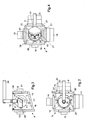
- Fig. 2
- den Dreiwegehahn in der Draufsicht,
- Fig. 3
- den Dreiwegehahn in der Vorderansicht und
- Fig. 4
- den Dreiwegehahn in der Unteransicht.
Claims (16)
- Mehrwegehahn (9) bestehend aus einem Gehäuse (19), an welchem entsprechend der Anzahl der Wege winklig zueinander versetzt Anschlussstellen (8,10,13,14) vorgesehen sind, und einen innerhalb des Gehäuses (19) drehbar gelagerten und von einem Betätigungselement (20) betätigbaren Stellelement (18), welches mit Ventilelementen (12,22,23), die zumindest einigen der Anschlussstellen (8,10,13,14)zugeordnet sind, um die zugeordnete Anschlussstelle (8,10,13,14)wahlweise zu verschließen oder freizugeben, zusammenwirken.
- Mehrwegehahn nach Anspruch 1, dadurch gekennzeichnet, dass einer Anschlussstelle (10) kein Ventilelement zugeordnet ist, dass diese Anschlussstelle (10) mit einer mit Unterdruck beaufschlagten Leitung (10) verbunden ist.
- Mehrwegehahn nach Anspruch 1, dadurch gekennzeichnet, dass die Ventilelemente (21,22,23) als Rückschlagventile ausgebildet sind.
- Mehrwegeeinheit nach einem oder mehreren der vorstehenden Ansprüche, dadurch gekennzeichnet, dass die Ventilelemente (21,22,23) als jeweils mit einem Gelenk (24) schwenkbar angeordnete Ventilklappen (21,22,23) ausgebildet sind.
- Mehrwegehahn nach einem oder mehreren der vorstehenden Ansprüche, dadurch gekennzeichnet, dass das Stellelement (18) eine der Anzahl der Ventilelemente (21,22,23) entsprechende und die Ventile (21,22,23) in Schließstellung bringende und haltende Betätigungsmittel (25,26,27) aufweist.
- Mehrwegehahn nach einem oder mehreren der vorstehenden Ansprüche, dadurch gekennzeichnet, dass die Betätigungsmittel (25,26,27) in der Nullstellung des Stellelementes (18) jeweils auf ein Ventilelement (21,22,23) einwirken.
- Mehrwegehahn nach einem oder mehreren der vorstehenden Ansprüche, dadurch gekennzeichnet, dass die Betätigungsmittel (25,26,27) federnd und in Richtung der Ventile (21,22,23) wirkende Elemente sind.
- Mehrwegehahn nach einem oder mehreren der vorstehenden Ansprüche, dadurch gekennzeichnet, dass die Betätigungsmittel (25,26,27) verschiebbar in dem Stellelement (18) angeordnet und in Richtung der Ventilelemente (21,22,23) federbelastet beaufschlagt sind.
- Mehrwegehahn nach einem oder mehreren der vorstehenden Ansprüche, dadurch gekennzeichnet, dass das Stellelement (18) in dem einer Anschlussstelle zugeordneten Bereich ein in Richtung der Drehachse (29) des Stellelemente (18) zurückspringenden Bereich (30) aufweist.
- Mehrwegehahn nach einem oder mehreren der vorstehenden Ansprüche, dadurch gekennzeichnet, dass die Anschlussstellen (8,10,13,14) und die Betätigungselemente (25,26,27) gleichförmig (gleichmäßig) verteilt angeordnet (gleiche Winkelaufteilung von Anschlussstelle zu Anschlussstelle bzw. von Betätigungsmittel zu Betätigungsmittel - zurückspringender Bereich) sind.
- Mehrwegehahn nach einem oder mehreren der vorstehenden Ansprüche, dadurch gekennzeichnet, dass einer Anschlussstelle an Stelle eines Betätigungselementes (25,26,27) des Stellelementes (18) der zurückspringende Bereich (30) des Stellelementes (18) zugeordnet ist.
- Mehrwegehahn nach einem oder mehreren der vorstehenden Ansprüche, dadurch gekennzeichnet, dass die die Betätigungsmittel (25,26,27) federnd beaufschlagenden Druckfedern (28) sich an dem Stellelement (18) abstützen.
- Mehrwegehahn nach einem oder mehreren der vorstehenden Ansprüche, dadurch gekennzeichnet, dass der als Ausgangsleitung (10) ausgebildete Anschlussstelle kein Ventilelement zugeordnet ist.
- Mehrwegehahn nach einem oder mehreren der vorstehenden Ansprüche, dadurch gekennzeichnet, dass das Stellelement (18) aus federndem Material hergestellt und eine Kurvenscheibe ist und im Querschnitt als sich über einen Winkelbereich der mit dem Stellelement versehenen Anschlussstelle entsprechenden, jedoch geringfügig vergrößertem Sektor kreisförmig ist und der übrige Bereich zurückspringend ausgebildet ist.
- Mehrwegehahn nach einem oder mehreren der vorstehenden Ansprüche, dadurch gekennzeichnet, dass der zurückspringende Bereich (30) des Stellelementes (18) abgeschrägt ausgebildet ist, dass das Ventilelement (21,22,23) in seiner Öffnungsposition an die abgeschrägte Fläche (30) anlegbar ist.
- Mehrwegehahn nach einem oder mehreren der vorstehenden Ansprüche, dadurch gekennzeichnet, dass das Stellelement (18) als Kurvenscheibe ausgebildet ist und deren folgenden Kurvenverlauf eine verkürzte Epizykloide ist.
Applications Claiming Priority (2)
| Application Number | Priority Date | Filing Date | Title |
|---|---|---|---|
| DE10154451 | 2001-11-06 | ||
| DE2001154451 DE10154451A1 (de) | 2001-11-06 | 2001-11-06 | Mehrwegehahn |
Publications (2)
| Publication Number | Publication Date |
|---|---|
| EP1308658A2 true EP1308658A2 (de) | 2003-05-07 |
| EP1308658A3 EP1308658A3 (de) | 2003-11-26 |
Family
ID=7704774
Family Applications (1)
| Application Number | Title | Priority Date | Filing Date |
|---|---|---|---|
| EP02024137A Withdrawn EP1308658A3 (de) | 2001-11-06 | 2002-10-30 | Mehrwegehahn |
Country Status (2)
| Country | Link |
|---|---|
| EP (1) | EP1308658A3 (de) |
| DE (1) | DE10154451A1 (de) |
Cited By (3)
| Publication number | Priority date | Publication date | Assignee | Title |
|---|---|---|---|---|
| EP1821012A2 (de) | 2006-02-15 | 2007-08-22 | Amazonen-Werke H. Dreyer GmbH & Co. KG | Mehrwegeventil |
| DE102007007870A1 (de) | 2007-02-14 | 2008-08-21 | Amazonen-Werke H. Dreyer Gmbh & Co. Kg | Mehrwegeventil |
| EP2336616A1 (de) * | 2009-12-15 | 2011-06-22 | Amazonen-Werke H. Dreyer GmbH & Co. KG | Mehrwegehahn |
Families Citing this family (1)
| Publication number | Priority date | Publication date | Assignee | Title |
|---|---|---|---|---|
| DE102020117754A1 (de) | 2020-07-06 | 2022-01-13 | Horsch Leeb Application Systems Gmbh | Mehrwegehahn mit Übersetzungsgetriebe und Anbaufeldspritze |
Family Cites Families (3)
| Publication number | Priority date | Publication date | Assignee | Title |
|---|---|---|---|---|
| BE555738A (de) * | ||||
| GB576628A (en) * | 1943-03-06 | 1946-04-12 | Curtis Pump Co | Improvements in or relating to selector valves |
| US3334658A (en) * | 1964-03-04 | 1967-08-08 | Randolph Mfg Co | Selector valve |
-
2001
- 2001-11-06 DE DE2001154451 patent/DE10154451A1/de not_active Withdrawn
-
2002
- 2002-10-30 EP EP02024137A patent/EP1308658A3/de not_active Withdrawn
Cited By (6)
| Publication number | Priority date | Publication date | Assignee | Title |
|---|---|---|---|---|
| EP1821012A2 (de) | 2006-02-15 | 2007-08-22 | Amazonen-Werke H. Dreyer GmbH & Co. KG | Mehrwegeventil |
| EP1821013A2 (de) | 2006-02-15 | 2007-08-22 | Amazonen-Werke H. Dreyer GmbH & Co. KG | Mehrwegeventil |
| EP1821012A3 (de) * | 2006-02-15 | 2010-04-21 | Amazonen-Werke H. Dreyer GmbH & Co. KG | Mehrwegeventil |
| EP1821013A3 (de) * | 2006-02-15 | 2014-12-03 | Amazonen-Werke H. Dreyer GmbH & Co. KG | Mehrwegeventil |
| DE102007007870A1 (de) | 2007-02-14 | 2008-08-21 | Amazonen-Werke H. Dreyer Gmbh & Co. Kg | Mehrwegeventil |
| EP2336616A1 (de) * | 2009-12-15 | 2011-06-22 | Amazonen-Werke H. Dreyer GmbH & Co. KG | Mehrwegehahn |
Also Published As
| Publication number | Publication date |
|---|---|
| EP1308658A3 (de) | 2003-11-26 |
| DE10154451A1 (de) | 2003-05-22 |
Similar Documents
| Publication | Publication Date | Title |
|---|---|---|
| WO2014000726A2 (de) | Vorrichtung und verfahren zur schaltbaren förderung wenigstens eines mediums | |
| EP0098419B1 (de) | Vorrichtung zum Zumischen von Desinfektionsmittel zu Wasser | |
| DE3902116C1 (en) | Device for adding a fluid additive, such as liquid soap or deodorant, to shower water | |
| EP1821017A2 (de) | Mehrwegeventil | |
| EP1308658A2 (de) | Mehrwegehahn | |
| EP0472860A1 (de) | Geschlossenes landwirtschaftliches Feldspritzensystem | |
| DE102007012796A1 (de) | Spritzeinrichtung | |
| DE2808196A1 (de) | Hydraulische steuereinrichtung | |
| DE60301988T2 (de) | Wasserauslassventil | |
| DE19754558B4 (de) | Flaschendosierer | |
| EP1821012A2 (de) | Mehrwegeventil | |
| DE102016106039B4 (de) | Wasserpumpe mit Rückschlagventil | |
| DE2849704A1 (de) | Hydraulisches steuergeraet | |
| EP0353547B1 (de) | Saugwagen zum Entsorgen von Schlämmen und Flüssigkeiten | |
| DE829257C (de) | Kreiselpumpe zum Aufruehren und Foerdern von Dickstoffen (Jauche, Schlamm usw.) aus Gruben | |
| DE2613662C2 (de) | Vorrichtung zur chemisch-mechanischen Reinigung der Getränkeförderleitungen einer Getränkeschankanlage | |
| EP1240826A2 (de) | Sprühvorrichtung | |
| DE102007007870A1 (de) | Mehrwegeventil | |
| DE3602079A1 (de) | Vorrichtung zum umfuellen von fluessigkeiten | |
| CH657174A5 (en) | Apparatus for producing wet screed flooring, which is ready for processing, from dry screed flooring and water | |
| DE3201313A1 (de) | Geschlossenes system zum pumpen von fluessigkeiten sowie kraftuebertragungsanordnung fuer ein derartiges system | |
| DE241961C (de) | ||
| DE102010002802B4 (de) | Feldspritzsystem | |
| DE102007007869A1 (de) | Mehrwegeventil | |
| DE4005430A1 (de) | Erntemaschine, insbesondere selbstladewagen mit einer hydraulischen steuervorrichtung |
Legal Events
| Date | Code | Title | Description |
|---|---|---|---|
| PUAI | Public reference made under article 153(3) epc to a published international application that has entered the european phase |
Free format text: ORIGINAL CODE: 0009012 |
|
| AK | Designated contracting states |
Designated state(s): AT BE BG CH CY CZ DE DK EE ES FI FR GB GR IE IT LI LU MC NL PT SE SK TR |
|
| AX | Request for extension of the european patent |
Extension state: AL LT LV MK RO SI |
|
| PUAL | Search report despatched |
Free format text: ORIGINAL CODE: 0009013 |
|
| AK | Designated contracting states |
Kind code of ref document: A3 Designated state(s): AT BE BG CH CY CZ DE DK EE ES FI FR GB GR IE IT LI LU MC NL PT SE SK TR |
|
| AX | Request for extension of the european patent |
Extension state: AL LT LV MK RO SI |
|
| RIC1 | Information provided on ipc code assigned before grant |
Ipc: 7F 16K 11/16 B Ipc: 7A 01M 7/00 B Ipc: 7F 16K 27/06 B Ipc: 7F 16K 11/085 A |
|
| AKX | Designation fees paid | ||
| REG | Reference to a national code |
Ref country code: DE Ref legal event code: 8566 |
|
| STAA | Information on the status of an ep patent application or granted ep patent |
Free format text: STATUS: THE APPLICATION IS DEEMED TO BE WITHDRAWN |
|
| 18D | Application deemed to be withdrawn |
Effective date: 20040527 |