EP1308641A1 - Führungswagen für Profilschienenführungen - Google Patents
Führungswagen für Profilschienenführungen Download PDFInfo
- Publication number
- EP1308641A1 EP1308641A1 EP02024156A EP02024156A EP1308641A1 EP 1308641 A1 EP1308641 A1 EP 1308641A1 EP 02024156 A EP02024156 A EP 02024156A EP 02024156 A EP02024156 A EP 02024156A EP 1308641 A1 EP1308641 A1 EP 1308641A1
- Authority
- EP
- European Patent Office
- Prior art keywords
- guide carriage
- guide
- carriage according
- cage
- rolling elements
- Prior art date
- Legal status (The legal status is an assumption and is not a legal conclusion. Google has not performed a legal analysis and makes no representation as to the accuracy of the status listed.)
- Granted
Links
- 238000005096 rolling process Methods 0.000 claims abstract description 39
- 238000003466 welding Methods 0.000 claims abstract description 9
- 238000000034 method Methods 0.000 claims abstract description 5
- 230000004087 circulation Effects 0.000 claims description 22
- 125000006850 spacer group Chemical group 0.000 claims description 22
- 238000000926 separation method Methods 0.000 claims description 6
- 238000004026 adhesive bonding Methods 0.000 claims description 4
- 238000005304 joining Methods 0.000 claims description 4
- 238000007789 sealing Methods 0.000 claims 1
- 239000000853 adhesive Substances 0.000 abstract 1
- 230000001070 adhesive effect Effects 0.000 abstract 1
- 238000004519 manufacturing process Methods 0.000 description 3
- 230000000694 effects Effects 0.000 description 1
- 238000009434 installation Methods 0.000 description 1
- 238000005507 spraying Methods 0.000 description 1
Images




Classifications
-
- F—MECHANICAL ENGINEERING; LIGHTING; HEATING; WEAPONS; BLASTING
- F16—ENGINEERING ELEMENTS AND UNITS; GENERAL MEASURES FOR PRODUCING AND MAINTAINING EFFECTIVE FUNCTIONING OF MACHINES OR INSTALLATIONS; THERMAL INSULATION IN GENERAL
- F16C—SHAFTS; FLEXIBLE SHAFTS; ELEMENTS OR CRANKSHAFT MECHANISMS; ROTARY BODIES OTHER THAN GEARING ELEMENTS; BEARINGS
- F16C29/00—Bearings for parts moving only linearly
- F16C29/04—Ball or roller bearings
- F16C29/06—Ball or roller bearings in which the rolling bodies circulate partly without carrying load
- F16C29/0633—Ball or roller bearings in which the rolling bodies circulate partly without carrying load with a bearing body defining a U-shaped carriage, i.e. surrounding a guide rail or track on three sides
- F16C29/0652—Ball or roller bearings in which the rolling bodies circulate partly without carrying load with a bearing body defining a U-shaped carriage, i.e. surrounding a guide rail or track on three sides whereby the return paths are at least partly defined by separate parts, e.g. covers attached to the legs of the main body of the U-shaped carriage
- F16C29/0654—Ball or roller bearings in which the rolling bodies circulate partly without carrying load with a bearing body defining a U-shaped carriage, i.e. surrounding a guide rail or track on three sides whereby the return paths are at least partly defined by separate parts, e.g. covers attached to the legs of the main body of the U-shaped carriage with balls
- F16C29/0659—Ball or roller bearings in which the rolling bodies circulate partly without carrying load with a bearing body defining a U-shaped carriage, i.e. surrounding a guide rail or track on three sides whereby the return paths are at least partly defined by separate parts, e.g. covers attached to the legs of the main body of the U-shaped carriage with balls with four rows of balls
- F16C29/0661—Ball or roller bearings in which the rolling bodies circulate partly without carrying load with a bearing body defining a U-shaped carriage, i.e. surrounding a guide rail or track on three sides whereby the return paths are at least partly defined by separate parts, e.g. covers attached to the legs of the main body of the U-shaped carriage with balls with four rows of balls with load directions in O-arrangement
-
- F—MECHANICAL ENGINEERING; LIGHTING; HEATING; WEAPONS; BLASTING
- F16—ENGINEERING ELEMENTS AND UNITS; GENERAL MEASURES FOR PRODUCING AND MAINTAINING EFFECTIVE FUNCTIONING OF MACHINES OR INSTALLATIONS; THERMAL INSULATION IN GENERAL
- F16C—SHAFTS; FLEXIBLE SHAFTS; ELEMENTS OR CRANKSHAFT MECHANISMS; ROTARY BODIES OTHER THAN GEARING ELEMENTS; BEARINGS
- F16C33/00—Parts of bearings; Special methods for making bearings or parts thereof
- F16C33/30—Parts of ball or roller bearings
- F16C33/37—Loose spacing bodies
- F16C33/3706—Loose spacing bodies with concave surfaces conforming to the shape of the rolling elements, e.g. the spacing bodies are in sliding contact with the rolling elements
-
- F—MECHANICAL ENGINEERING; LIGHTING; HEATING; WEAPONS; BLASTING
- F16—ENGINEERING ELEMENTS AND UNITS; GENERAL MEASURES FOR PRODUCING AND MAINTAINING EFFECTIVE FUNCTIONING OF MACHINES OR INSTALLATIONS; THERMAL INSULATION IN GENERAL
- F16C—SHAFTS; FLEXIBLE SHAFTS; ELEMENTS OR CRANKSHAFT MECHANISMS; ROTARY BODIES OTHER THAN GEARING ELEMENTS; BEARINGS
- F16C33/00—Parts of bearings; Special methods for making bearings or parts thereof
- F16C33/30—Parts of ball or roller bearings
- F16C33/38—Ball cages
- F16C33/3825—Ball cages formed as a flexible belt, e.g. spacers connected by a thin film
-
- F—MECHANICAL ENGINEERING; LIGHTING; HEATING; WEAPONS; BLASTING
- F16—ENGINEERING ELEMENTS AND UNITS; GENERAL MEASURES FOR PRODUCING AND MAINTAINING EFFECTIVE FUNCTIONING OF MACHINES OR INSTALLATIONS; THERMAL INSULATION IN GENERAL
- F16C—SHAFTS; FLEXIBLE SHAFTS; ELEMENTS OR CRANKSHAFT MECHANISMS; ROTARY BODIES OTHER THAN GEARING ELEMENTS; BEARINGS
- F16C33/00—Parts of bearings; Special methods for making bearings or parts thereof
- F16C33/30—Parts of ball or roller bearings
- F16C33/38—Ball cages
- F16C33/40—Ball cages for multiple rows of balls
-
- F—MECHANICAL ENGINEERING; LIGHTING; HEATING; WEAPONS; BLASTING
- F16—ENGINEERING ELEMENTS AND UNITS; GENERAL MEASURES FOR PRODUCING AND MAINTAINING EFFECTIVE FUNCTIONING OF MACHINES OR INSTALLATIONS; THERMAL INSULATION IN GENERAL
- F16C—SHAFTS; FLEXIBLE SHAFTS; ELEMENTS OR CRANKSHAFT MECHANISMS; ROTARY BODIES OTHER THAN GEARING ELEMENTS; BEARINGS
- F16C33/00—Parts of bearings; Special methods for making bearings or parts thereof
- F16C33/30—Parts of ball or roller bearings
- F16C33/38—Ball cages
- F16C33/41—Ball cages comb-shaped
- F16C33/412—Massive or moulded comb cages, e.g. snap ball cages
- F16C33/414—Massive or moulded comb cages, e.g. snap ball cages formed as one-piece cages, i.e. monoblock comb cages
- F16C33/416—Massive or moulded comb cages, e.g. snap ball cages formed as one-piece cages, i.e. monoblock comb cages made from plastic, e.g. injection moulded comb cages
-
- F—MECHANICAL ENGINEERING; LIGHTING; HEATING; WEAPONS; BLASTING
- F16—ENGINEERING ELEMENTS AND UNITS; GENERAL MEASURES FOR PRODUCING AND MAINTAINING EFFECTIVE FUNCTIONING OF MACHINES OR INSTALLATIONS; THERMAL INSULATION IN GENERAL
- F16C—SHAFTS; FLEXIBLE SHAFTS; ELEMENTS OR CRANKSHAFT MECHANISMS; ROTARY BODIES OTHER THAN GEARING ELEMENTS; BEARINGS
- F16C2226/00—Joining parts; Fastening; Assembling or mounting parts
- F16C2226/50—Positive connections
- F16C2226/70—Positive connections with complementary interlocking parts
- F16C2226/76—Positive connections with complementary interlocking parts with tongue and groove or key and slot
- F16C2226/78—Positive connections with complementary interlocking parts with tongue and groove or key and slot of jigsaw-puzzle type
Definitions
- the invention relates to a guide carriage for linear guideways.
- a Such known guidance is shown in the document EP 0 351 499 B1.
- One of the main tasks of the chain is to align and pull in the rolling elements from the return to the load zone, can be with closed chains can only be solved incompletely.
- the rolling elements are, depending on the position of the Separation point, not pulled but pushed.
- a cage is shown in Japanese Patent Laid-Open No. 5-126 149 the shape known from commercially available self-aligning ball bearings. However, it is elastic about the central axis.
- Such a two-row cage is captive arranged between the rows of balls and can be used as a closed cage in the closed orbit of one of individual guide parts built circulation channel can be installed.
- the object of the invention is to provide a guide carriage in which a circulation system is generated with individual parts fixed to a supporting body can be an edgeless and therefore trouble-free circulation allows.
- a circulation should at least equate to one circulation, Rather, however, surpass this, as is the case with a linear bearing after Document EP 0 470 357 A1 results.
- the carriage should be optimal have a circulation channel oriented to the career path without the manufacturing process of ejection - which is advantageous for roller circulation units - to have to use.
- the manufacturing process used should allow to create particularly low-profile elements and full-spherical arrangements to be used with open or closed chains.
- a carriage is suggested for inside or externally profiled mounting rails, preferably in an O arrangement, on the one essentially C-shaped closed circulation channel is arranged, which Rolling element leads completely outside the bearing zone and the form-fitting is attached so that an edgeless circulation can take place.
- the guide parts, that form the channel are made on the face side by known joining methods, for example Ultrasonic welding, laser welding or gluing, connected, so that a self-holding bond is created.
- Figure 1 shows a carriage 1, partly in side view and partly in longitudinal section, the circumferential rolling elements 2 on a guide rail 3 supported and along this is movable. It consists of one Support body 4, on its two end faces pointing in the directions of movement Deflector 5 are arranged. These contain one as individual parts Circulation system parts of a cage 6, in which on each long side of the guide rail 3 two rows of rolling elements arranged one above the other are led.
- the attachment of a deflecting body 5 is indeed the support body 4 shown with a screw, but this can be omitted, since the attachment according to the invention is form-fitting or by welding or gluing.
- Figure 2 shows that in the guide carriage partially shown in cross section 1 the middle part of the cage 6 by two separate, upwards or downwards
- the narrowing of the career cross-sections is formed by a continuous Wall are separated.
- the cage 6 consists of one piece, on which both a rolling element retaining web 7 to the guide rail, as well as the Return channels are formed and which is positioned over a centering surface 8 is and completely surrounds a support body leg 9, so that at the assembly of the cage 6 from below in a straight line in the direction of Arrow 10 can be pushed onto the supporting body leg 9.
- the direct contact of the rolling elements 2 with the supporting body 4 of the carriage 1 prevented by a longitudinal bar 11.
- the lower row of rolling elements 2 is with an additional cover 12 closed.
- the centering surfaces 8 of the support body 4 can be together ground with the raceways of the support body 4 for the rolling elements 2 become.
- Figure 3 shows that in the guide carriage 1 grooves 13 for chain stays in the Raceways of the middle part of the cage 6 and / or the otherwise flat upper and lower boundary parts are introduced to accommodate Spacer connecting webs serve.
- Figure 4 shows that in the carriage 1, the orbits of the cage consist of two facing, cut C-shaped single shells, namely an upper cage element 14 and a lower cage element 15. These guide the rolling elements 2 designed as balls completely and alone. Their open sides face each other and their channels are in cross section narrowed on the open side. So here the cage is made of two horizontally separated components and thus enables use an endless chain for every row of rolling elements.
- Figure 5 shows that in the carriage 1 between the two cage elements 14 and 15 an additional retaining plate 16 is arranged. It can also several essentially flat or profiled or beveled Retaining plates may be arranged.
- Figure 6 shows a carriage 1, which is arranged in circulation Rolling element 2 is supported on a guide rail 3, partly in cross section and partly in front view.
- Figure 7 shows the section along line VII-VII of Figure 6.
- the rolling elements 2 are arranged in the circulations without spacers.
- On Each end face of the carriage 1 is a head piece 17 via a positive Connection 17a attached.
- FIG. 8 shows spacers 18 to be arranged between the rolling elements 2 as Single distance pieces, as they are in the linear areas of a Rolling element circulation can be arranged.
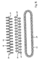
- FIG. 9 shows a chain 19 which consists of elastically connected spacers 18 exists, once in longitudinal section and once in side view.
- This revolving Chain 19 is not endless, but has two ends at a separation point 20 on.
- the spacers 18 can also be in an endless chain be connected to each other without a separation point.
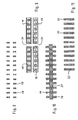
- Figure 10 shows a section of a chain 21 with which spacers 18 for two parallel rows of rolling elements are connected.
- the chain 21 is for balls as Rolling bodies formed. With such a double comb chain that runs endlessly two rows of rolling elements can be guided at the same time.
- FIG. 11 shows, like FIG. 8, spacers arranged as individual spacers 22, each with a spacer 22 rolling elements of two parallel Separates rows of rolling elements. So here are single “double comb spacers" used.
- FIG. 12 shows an arrangement which corresponds to the arrangements according to the figures 9 and 10 is comparable, the chain 23 each having two elastic webs connected spacer 18 for two parallel rows of rolling elements.
- FIGS. 13 and 14 each show that a endless double comb chain 24 is used, which consists of two horizontally separated Sub-chains 25 and 26 exist. Both partial chains are through a positive Connection 27 attached to each other.
- FIG. 15, like FIG. 14, shows that the spacers in the guide carriage of the individual circulation associations by half a division to each other are offset.
- the spacers 18 of the endlessly executed Double comb chain 28 connected to one another via elastic spring bars 29, to be able to absorb strains.
Landscapes
- Engineering & Computer Science (AREA)
- General Engineering & Computer Science (AREA)
- Mechanical Engineering (AREA)
- Bearings For Parts Moving Linearly (AREA)
Abstract
Description
- 1
- Führungswagen
- 2
- Wälzkörper
- 3
- Führungsschiene
- 4
- Tragkörper
- 5
- Umlenkkörper
- 6
- Käfig
- 7
- Wälzkörperrückhaltesteg
- 8
- Zentrierfläche
- 9
- Tragkörperschenkel
- 10
- Pfeil, geradlinige Bewegung
- 11
- Längsleiste
- 12
- Verschlußdeckel
- 13
- Nut
- 14
- oberes Käfigelement
- 15
- unteres Käfigelement
- 16
- Rückhalteplatte
- 17
- Kopfstück
- 17a
- formschlüssige Verbindung
- 18
- Distanzhalter
- 19
- Kette
- 20
- Trennstelle
- 21
- Kette
- 22
- Doppelkamm-Distanzhalter
- 23
- Kette
- 24
- Doppelkammkette
- 25
- Teilkette
- 26
- Teilkette
- 27
- formschlüssige Verbindung
- 28
- Doppelkammkette
- 29
- Federsteg
Claims (15)
- Führungswagen (1) für eine Profilschienenführung, welche als Linearlager mit umlaufenden Wälzkörpern (2) ausgebildet ist, gekennzeichnet durch Führungsteile, die im wesentlichen C-förmige, geschlossene Umlaufkanäle bilden, welche jeweils die Wälzkörper (2) vollständig außerhalb einer Tragzone führen und formschlüssig befestigt sind.
- Führungswagen nach Anspruch 1, dadurch gekennzeichnet, dass daran die Führungsteile, die einen Umlaufkanal bilden, durch bekannte Fügeverfahren, wie Ultraschallschweißen, Laserschweißen oder Kleben, stirnseitig befestigt sind.
- Führungswagen mit an einem Tragkörper (4) befestigten Einzelteilen für zwei-, vier-, sechs- oder achtreihige Kugelführungen für begrenzte oder unbegrenzte Hubwege, für vollkugelige Anordnungen, für Anordnungen mit Zwischenstücken oder für Anordnungen mit verbundenen Zwischenstücken, (also Ketten), nicht geschlossen oder geschlossen, dadurch gekennzeichnet, dass die einen kantenlosen, geschlossenen Umlauf oder Umlaufkanäle bildenden Einzelteile aus Kunststoff bestehen und wenigstens an den Stirnseiten des Führungswagens, der die Traglaufbahnen enthält, durch bekannte Fügeverfahren wie Ultraschallschweißen, Laserschweißen, Kleben oder andere Fügeverfahren verbunden sind, so dass sich in sich stabile und geschlossene Wälzkörperführungskanäle ergeben, die durch Formschluß seitlich, unten oder stirnseitig am Tragkörper gehalten und angebracht werden.
- Führungswagen nach Anspruch 1, dadurch gekennzeichnet, dass ein umlaufender Käfig (6) einstückig ausgeführt ist und sowohl einen Wälzkörperhaltesteg (7) zu einer Führungsschiene (3) hin, an welcher der Führungswagen (1) über die Wälzkörper (2) verschiebbar abgestützt ist, als auch einen Rücklaufkanal ausbildet und an einem Tragkörper (4) des Führungswagens (1) über eine Zentrierfläche (8) positioniert ist und einen Tragkörperschenkel (9) vollständig umschließt.
- Führungswagen nach Anspruch 4, dadurch gekennzeichnet, dass der Käfig (6) in geradliniger Bewegung (10) von dem freien Enden des Tragkörperschenkels (9) aus auf diesen aufgeschoben ist.
- Führungswagen nach Anspruch 4, dadurch gekennzeichnet, dass der Käfig aus zwei getrennten Bauteilen, und zwar einem oberen Käfigelement (14) und einem unteren Käfigelement (15), zusammengesetzt ist.
- Führungswagen nach Anspruch 6, dadurch gekennzeichnet, dass zur Befestigung der Käfigelemente (14, 15) ein Kopfstück (17) über eine formschlüssige Verbindung (17a) an dem Führungswagen (1) gehalten ist.
- Führungswagen nach Anspruch 1, dadurch gekennzeichnet, dass zwei parallele Reihen von Wälzkörpern (2) gleichzeitig von einer endlosen, mit einer Doppelkammanordnung von Distanzhaltern (18) versehenen Kette (21) geführt sind.
- Führungswagen nach Anspruch 8, dadurch gekennzeichnet, dass die Doppelkammkette (24) aus zwei einzelnen Teilketten (25, 26) zusammengesetzt ist, welche formschlüssig miteinander verbunden sind.
- Führungswagen nach Anspruch 8, dadurch gekennzeichnet, dass die Distanzhalter (18) der endlos ausgeführte Doppelkammkette (28) über elastische Federstege (29) miteinander verbunden sind.
- Führungswagen nach Anspruch 1, dadurch gekennzeichnet, dass die umlaufenden Wälzkörper (2) durch einzelne Distanzhalter (18) oder durch Doppelkamm-Distanzhalter (22) voneinander getrennt sind.
- Führungswagen nach Anspruch 4, dadurch gekennzeichnet, dass in einem Rücklaufkanal eine die Berührung der Wälzkörper (2) mit dem Tragkörper (4) verhindernde Längsleiste (11) angeordnet ist.
- Führungswagen nach Anspruch 4, dadurch gekennzeichnet, dass ein Rücklaufkanal mit einem Verschlußdeckel (12) nach außen verschlossen ist.
- Führungswagen nach Anspruch 4, dadurch gekennzeichnet, dass an dem Tragkörper (4) Zentrierflächen (8) gemeinsam mit Laufbahnen für tragende Wälzkörper (2) in einem Arbeitsgang geschliffen sind.
- Führungswagen nach Anspruch 4, dadurch gekennzeichnet, dass der umlaufende Käfig mit zusammenhängenden, Distanzhalter (18) enthaltenden Kettengliedern als Einzelkette oder Doppelkette endlos oder mit zwei Enden ausgeführt ist, die durch eine Trennstelle (20) gebildet sind.
Priority Applications (1)
| Application Number | Priority Date | Filing Date | Title |
|---|---|---|---|
| EP08154766A EP1953401B1 (de) | 2001-11-05 | 2002-10-30 | Führungswagen für Profilschienenführungen |
Applications Claiming Priority (2)
| Application Number | Priority Date | Filing Date | Title |
|---|---|---|---|
| DE2001153831 DE10153831A1 (de) | 2001-11-05 | 2001-11-05 | Führungswagen für Profilschienenführungen |
| DE10153831 | 2001-11-05 |
Related Child Applications (1)
| Application Number | Title | Priority Date | Filing Date |
|---|---|---|---|
| EP08154766A Division EP1953401B1 (de) | 2001-11-05 | 2002-10-30 | Führungswagen für Profilschienenführungen |
Publications (2)
| Publication Number | Publication Date |
|---|---|
| EP1308641A1 true EP1308641A1 (de) | 2003-05-07 |
| EP1308641B1 EP1308641B1 (de) | 2009-01-07 |
Family
ID=7704387
Family Applications (2)
| Application Number | Title | Priority Date | Filing Date |
|---|---|---|---|
| EP20020024156 Expired - Lifetime EP1308641B1 (de) | 2001-11-05 | 2002-10-30 | Führungswagen für Profilschienenführungen |
| EP08154766A Expired - Lifetime EP1953401B1 (de) | 2001-11-05 | 2002-10-30 | Führungswagen für Profilschienenführungen |
Family Applications After (1)
| Application Number | Title | Priority Date | Filing Date |
|---|---|---|---|
| EP08154766A Expired - Lifetime EP1953401B1 (de) | 2001-11-05 | 2002-10-30 | Führungswagen für Profilschienenführungen |
Country Status (3)
| Country | Link |
|---|---|
| EP (2) | EP1308641B1 (de) |
| DE (2) | DE10153831A1 (de) |
| ES (2) | ES2317975T3 (de) |
Cited By (4)
| Publication number | Priority date | Publication date | Assignee | Title |
|---|---|---|---|---|
| EP1387098A2 (de) | 2002-08-03 | 2004-02-04 | Ina Schaeffler KG | Linearwälzlager |
| EP1319853A3 (de) * | 2001-12-13 | 2005-06-01 | NSK Ltd., | Linearführungsvorrichtung und ihr Herstellungsverfahren |
| FR2918959A1 (fr) * | 2007-07-19 | 2009-01-23 | Laselec Sa | Procede et dispositif de fabrication d'un manchon autour d'un cable et d'identification d'un cable |
| US20200191199A1 (en) * | 2017-04-07 | 2020-06-18 | Thk Co., Ltd. | Ball housing band and motion guide apparatus |
Families Citing this family (2)
| Publication number | Priority date | Publication date | Assignee | Title |
|---|---|---|---|---|
| JP6530010B2 (ja) * | 2017-05-23 | 2019-06-12 | Thk株式会社 | 複列転動体収容バンド及び運動案内装置 |
| DE102020102644A1 (de) | 2020-02-03 | 2021-08-05 | Liebherr-Verzahntechnik Gmbh | Teleskopschiene |
Citations (7)
| Publication number | Priority date | Publication date | Assignee | Title |
|---|---|---|---|---|
| FR2522749A1 (fr) * | 1982-03-03 | 1983-09-09 | Skf Kugellagerfabriken Gmbh | Segment de roulement avec corps roulants |
| DE3913297A1 (de) * | 1989-04-22 | 1990-11-08 | Werner Jacob | Rollenumlaufschuh fuer eine linearfuehrung |
| EP0845611A1 (de) * | 1996-06-18 | 1998-06-03 | Thk Co. Ltd. | Linearführungvorrichtung mit mehreren kugelkettenreihen |
| US5829883A (en) * | 1996-10-09 | 1998-11-03 | Thk Co., Ltd. | Rolling motion guide apparatus |
| EP0890754A1 (de) * | 1997-01-17 | 1999-01-13 | Thk Co. Ltd. | Kugelkette |
| DE19941926A1 (de) * | 1998-09-11 | 2000-03-16 | Schaeffler Waelzlager Ohg | Linearwälzlager |
| DE10005719A1 (de) * | 2000-02-09 | 2001-08-16 | Schaeffler Waelzlager Ohg | Linearwälzlager |
Family Cites Families (4)
| Publication number | Priority date | Publication date | Assignee | Title |
|---|---|---|---|---|
| DE2202550A1 (de) * | 1972-01-20 | 1973-08-09 | Skf Kugellagerfabriken Gmbh | Waelzlager mit klemmeinrichtung fuer eine drehrichtung |
| DE3824191A1 (de) | 1988-07-16 | 1990-01-18 | Werner Jacob | Umlauffuehrung fuer waelzkoerper |
| DE4022168C2 (de) | 1990-07-12 | 1994-06-23 | Ina Lineartechnik Ohg | Linearlager |
| JPH0672610B2 (ja) | 1991-11-05 | 1994-09-14 | テイエチケー株式会社 | 複列ボ−ルチェイン |
-
2001
- 2001-11-05 DE DE2001153831 patent/DE10153831A1/de not_active Ceased
-
2002
- 2002-10-30 EP EP20020024156 patent/EP1308641B1/de not_active Expired - Lifetime
- 2002-10-30 DE DE50213196T patent/DE50213196D1/de not_active Expired - Lifetime
- 2002-10-30 ES ES02024156T patent/ES2317975T3/es not_active Expired - Lifetime
- 2002-10-30 ES ES08154766T patent/ES2380838T3/es not_active Expired - Lifetime
- 2002-10-30 EP EP08154766A patent/EP1953401B1/de not_active Expired - Lifetime
Patent Citations (7)
| Publication number | Priority date | Publication date | Assignee | Title |
|---|---|---|---|---|
| FR2522749A1 (fr) * | 1982-03-03 | 1983-09-09 | Skf Kugellagerfabriken Gmbh | Segment de roulement avec corps roulants |
| DE3913297A1 (de) * | 1989-04-22 | 1990-11-08 | Werner Jacob | Rollenumlaufschuh fuer eine linearfuehrung |
| EP0845611A1 (de) * | 1996-06-18 | 1998-06-03 | Thk Co. Ltd. | Linearführungvorrichtung mit mehreren kugelkettenreihen |
| US5829883A (en) * | 1996-10-09 | 1998-11-03 | Thk Co., Ltd. | Rolling motion guide apparatus |
| EP0890754A1 (de) * | 1997-01-17 | 1999-01-13 | Thk Co. Ltd. | Kugelkette |
| DE19941926A1 (de) * | 1998-09-11 | 2000-03-16 | Schaeffler Waelzlager Ohg | Linearwälzlager |
| DE10005719A1 (de) * | 2000-02-09 | 2001-08-16 | Schaeffler Waelzlager Ohg | Linearwälzlager |
Cited By (8)
| Publication number | Priority date | Publication date | Assignee | Title |
|---|---|---|---|---|
| EP1319853A3 (de) * | 2001-12-13 | 2005-06-01 | NSK Ltd., | Linearführungsvorrichtung und ihr Herstellungsverfahren |
| US7303335B2 (en) | 2001-12-13 | 2007-12-04 | Nsk Ltd. | Linear-motion device and method of manufacturing the same |
| EP1387098A2 (de) | 2002-08-03 | 2004-02-04 | Ina Schaeffler KG | Linearwälzlager |
| EP1387098A3 (de) * | 2002-08-03 | 2005-08-10 | Ina Schaeffler KG | Linearwälzlager |
| FR2918959A1 (fr) * | 2007-07-19 | 2009-01-23 | Laselec Sa | Procede et dispositif de fabrication d'un manchon autour d'un cable et d'identification d'un cable |
| WO2009034251A1 (fr) * | 2007-07-19 | 2009-03-19 | Laselec | Procédé et dispositif de fabrication d'un manchon autour d'un câble et d'identification d'un câble |
| US20200191199A1 (en) * | 2017-04-07 | 2020-06-18 | Thk Co., Ltd. | Ball housing band and motion guide apparatus |
| US10900519B2 (en) * | 2017-04-07 | 2021-01-26 | Thk Co., Ltd. | Ball housing band and motion guide apparatus |
Also Published As
| Publication number | Publication date |
|---|---|
| EP1953401A3 (de) | 2008-08-13 |
| DE10153831A1 (de) | 2003-05-15 |
| EP1308641B1 (de) | 2009-01-07 |
| ES2380838T3 (es) | 2012-05-18 |
| EP1953401A2 (de) | 2008-08-06 |
| DE50213196D1 (de) | 2009-02-26 |
| EP1953401B1 (de) | 2012-02-01 |
| ES2317975T3 (es) | 2009-05-01 |
Similar Documents
| Publication | Publication Date | Title |
|---|---|---|
| DE3931397C2 (de) | ||
| EP0211243B1 (de) | Wälzlager für Linearbewegungen | |
| EP0472167B1 (de) | Wälzlager für Linearbewegungen, Stichwort: Rollenschienenführung | |
| DE3304783C2 (de) | ||
| DE3621381A1 (de) | Zweireihige waelzlagereinheit | |
| DE3688289T2 (de) | Beweglicher tisch. | |
| EP0481470A1 (de) | Elastischer Lagerblock für eine Linearführung | |
| EP0802337B1 (de) | Linearwälzlager | |
| DE3311857C2 (de) | Linearlager | |
| EP1110005B1 (de) | Linearwälzlager | |
| EP0504951B1 (de) | Verfahren zum Einbau einer Längsdichtungsleiste in eine Linearkugelbüchse und Längsdichtungsleiste zur Durchführung dieses Verfahrens | |
| DE3347869C2 (de) | ||
| DE3527886A1 (de) | Waelzlager fuer linearbewegungen | |
| EP1308641B1 (de) | Führungswagen für Profilschienenführungen | |
| DE9011444U1 (de) | Wälzlager für Linearbewegungen | |
| EP1552171A1 (de) | Linearführungseinheit | |
| DE3542478A1 (de) | Linearkugellager fuer schlitten in werkzeugmaschinen oder dgl. | |
| EP0601028A1 (de) | Wälzlager für linearbewegungen. | |
| EP1124067B1 (de) | Linearwälzlager | |
| EP1039158A2 (de) | Linearwälzlagerelement | |
| DE2834209A1 (de) | Waelzlager fuer laengsbewegungen | |
| EP1303706B1 (de) | Linearwälzlager | |
| DE3038377A1 (de) | Rollenumlaufschuh | |
| DE9300316U1 (de) | Wälzlager für Längsbewegungen | |
| DE19615723A1 (de) | Linearwälzlager |
Legal Events
| Date | Code | Title | Description |
|---|---|---|---|
| PUAI | Public reference made under article 153(3) epc to a published international application that has entered the european phase |
Free format text: ORIGINAL CODE: 0009012 |
|
| 17P | Request for examination filed |
Effective date: 20021030 |
|
| AK | Designated contracting states |
Designated state(s): AT BE BG CH CY CZ DE DK EE ES FI FR GB GR IE IT LI LU MC NL PT SE SK TR |
|
| AX | Request for extension of the european patent |
Extension state: AL LT LV MK RO SI |
|
| AKX | Designation fees paid |
Designated state(s): DE ES FR GB |
|
| 17Q | First examination report despatched |
Effective date: 20050509 |
|
| RAP1 | Party data changed (applicant data changed or rights of an application transferred) |
Owner name: SCHAEFFLER KG |
|
| 17Q | First examination report despatched |
Effective date: 20050509 |
|
| GRAP | Despatch of communication of intention to grant a patent |
Free format text: ORIGINAL CODE: EPIDOSNIGR1 |
|
| GRAS | Grant fee paid |
Free format text: ORIGINAL CODE: EPIDOSNIGR3 |
|
| GRAA | (expected) grant |
Free format text: ORIGINAL CODE: 0009210 |
|
| AK | Designated contracting states |
Kind code of ref document: B1 Designated state(s): DE ES FR GB |
|
| REG | Reference to a national code |
Ref country code: GB Ref legal event code: FG4D Free format text: NOT ENGLISH |
|
| REF | Corresponds to: |
Ref document number: 50213196 Country of ref document: DE Date of ref document: 20090226 Kind code of ref document: P |
|
| REG | Reference to a national code |
Ref country code: ES Ref legal event code: FG2A Ref document number: 2317975 Country of ref document: ES Kind code of ref document: T3 |
|
| PLBE | No opposition filed within time limit |
Free format text: ORIGINAL CODE: 0009261 |
|
| STAA | Information on the status of an ep patent application or granted ep patent |
Free format text: STATUS: NO OPPOSITION FILED WITHIN TIME LIMIT |
|
| 26N | No opposition filed |
Effective date: 20091008 |
|
| PGFP | Annual fee paid to national office [announced via postgrant information from national office to epo] |
Ref country code: GB Payment date: 20101029 Year of fee payment: 9 |
|
| REG | Reference to a national code |
Ref country code: GB Ref legal event code: 732E Free format text: REGISTERED BETWEEN 20110407 AND 20110413 |
|
| PGFP | Annual fee paid to national office [announced via postgrant information from national office to epo] |
Ref country code: ES Payment date: 20111124 Year of fee payment: 10 Ref country code: FR Payment date: 20111115 Year of fee payment: 10 |
|
| PGFP | Annual fee paid to national office [announced via postgrant information from national office to epo] |
Ref country code: DE Payment date: 20120102 Year of fee payment: 10 |
|
| REG | Reference to a national code |
Ref country code: DE Ref legal event code: R081 Ref document number: 50213196 Country of ref document: DE Owner name: SCHAEFFLER TECHNOLOGIES AG & CO. KG, DE Free format text: FORMER OWNER: SCHAEFFLER TECHNOLOGIES GMBH & CO. KG, 91074 HERZOGENAURACH, DE Effective date: 20120828 |
|
| GBPC | Gb: european patent ceased through non-payment of renewal fee |
Effective date: 20121030 |
|
| REG | Reference to a national code |
Ref country code: FR Ref legal event code: ST Effective date: 20130628 |
|
| PG25 | Lapsed in a contracting state [announced via postgrant information from national office to epo] |
Ref country code: DE Free format text: LAPSE BECAUSE OF NON-PAYMENT OF DUE FEES Effective date: 20130501 Ref country code: GB Free format text: LAPSE BECAUSE OF NON-PAYMENT OF DUE FEES Effective date: 20121030 |
|
| REG | Reference to a national code |
Ref country code: DE Ref legal event code: R119 Ref document number: 50213196 Country of ref document: DE Effective date: 20130501 |
|
| PG25 | Lapsed in a contracting state [announced via postgrant information from national office to epo] |
Ref country code: FR Free format text: LAPSE BECAUSE OF NON-PAYMENT OF DUE FEES Effective date: 20121031 |
|
| REG | Reference to a national code |
Ref country code: ES Ref legal event code: FD2A Effective date: 20140527 |
|
| PG25 | Lapsed in a contracting state [announced via postgrant information from national office to epo] |
Ref country code: ES Free format text: LAPSE BECAUSE OF NON-PAYMENT OF DUE FEES Effective date: 20121031 |
|
| P01 | Opt-out of the competence of the unified patent court (upc) registered |
Effective date: 20230522 |