EP1308600A1 - Kühlsystem für eine Gasturbine - Google Patents
Kühlsystem für eine Gasturbine Download PDFInfo
- Publication number
- EP1308600A1 EP1308600A1 EP02257513A EP02257513A EP1308600A1 EP 1308600 A1 EP1308600 A1 EP 1308600A1 EP 02257513 A EP02257513 A EP 02257513A EP 02257513 A EP02257513 A EP 02257513A EP 1308600 A1 EP1308600 A1 EP 1308600A1
- Authority
- EP
- European Patent Office
- Prior art keywords
- manifold
- return
- rotor
- buckets
- supply
- Prior art date
- Legal status (The legal status is an assumption and is not a legal conclusion. Google has not performed a legal analysis and makes no representation as to the accuracy of the status listed.)
- Granted
Links
- 238000001816 cooling Methods 0.000 title claims abstract description 90
- 230000014759 maintenance of location Effects 0.000 claims abstract description 12
- 238000006073 displacement reaction Methods 0.000 claims abstract description 11
- 239000002826 coolant Substances 0.000 claims description 76
- 125000006850 spacer group Chemical group 0.000 claims description 72
- 230000005540 biological transmission Effects 0.000 abstract 1
- 239000007789 gas Substances 0.000 description 12
- 238000011084 recovery Methods 0.000 description 5
- 230000000694 effects Effects 0.000 description 3
- 238000010276 construction Methods 0.000 description 2
- 238000002485 combustion reaction Methods 0.000 description 1
- 238000010248 power generation Methods 0.000 description 1
- 230000000717 retained effect Effects 0.000 description 1
Images


Classifications
-
- F—MECHANICAL ENGINEERING; LIGHTING; HEATING; WEAPONS; BLASTING
- F01—MACHINES OR ENGINES IN GENERAL; ENGINE PLANTS IN GENERAL; STEAM ENGINES
- F01D—NON-POSITIVE DISPLACEMENT MACHINES OR ENGINES, e.g. STEAM TURBINES
- F01D5/00—Blades; Blade-carrying members; Heating, heat-insulating, cooling or antivibration means on the blades or the members
- F01D5/02—Blade-carrying members, e.g. rotors
- F01D5/08—Heating, heat-insulating or cooling means
-
- F—MECHANICAL ENGINEERING; LIGHTING; HEATING; WEAPONS; BLASTING
- F01—MACHINES OR ENGINES IN GENERAL; ENGINE PLANTS IN GENERAL; STEAM ENGINES
- F01D—NON-POSITIVE DISPLACEMENT MACHINES OR ENGINES, e.g. STEAM TURBINES
- F01D5/00—Blades; Blade-carrying members; Heating, heat-insulating, cooling or antivibration means on the blades or the members
- F01D5/02—Blade-carrying members, e.g. rotors
- F01D5/06—Rotors for more than one axial stage, e.g. of drum or multiple disc type; Details thereof, e.g. shafts, shaft connections
-
- F—MECHANICAL ENGINEERING; LIGHTING; HEATING; WEAPONS; BLASTING
- F01—MACHINES OR ENGINES IN GENERAL; ENGINE PLANTS IN GENERAL; STEAM ENGINES
- F01D—NON-POSITIVE DISPLACEMENT MACHINES OR ENGINES, e.g. STEAM TURBINES
- F01D5/00—Blades; Blade-carrying members; Heating, heat-insulating, cooling or antivibration means on the blades or the members
- F01D5/02—Blade-carrying members, e.g. rotors
- F01D5/08—Heating, heat-insulating or cooling means
- F01D5/081—Cooling fluid being directed on the side of the rotor disc or at the roots of the blades
- F01D5/084—Cooling fluid being directed on the side of the rotor disc or at the roots of the blades the fluid circulating at the periphery of a multistage rotor, e.g. of drum type
-
- F—MECHANICAL ENGINEERING; LIGHTING; HEATING; WEAPONS; BLASTING
- F01—MACHINES OR ENGINES IN GENERAL; ENGINE PLANTS IN GENERAL; STEAM ENGINES
- F01D—NON-POSITIVE DISPLACEMENT MACHINES OR ENGINES, e.g. STEAM TURBINES
- F01D5/00—Blades; Blade-carrying members; Heating, heat-insulating, cooling or antivibration means on the blades or the members
- F01D5/02—Blade-carrying members, e.g. rotors
- F01D5/08—Heating, heat-insulating or cooling means
- F01D5/085—Heating, heat-insulating or cooling means cooling fluid circulating inside the rotor
-
- F—MECHANICAL ENGINEERING; LIGHTING; HEATING; WEAPONS; BLASTING
- F05—INDEXING SCHEMES RELATING TO ENGINES OR PUMPS IN VARIOUS SUBCLASSES OF CLASSES F01-F04
- F05D—INDEXING SCHEME FOR ASPECTS RELATING TO NON-POSITIVE-DISPLACEMENT MACHINES OR ENGINES, GAS-TURBINES OR JET-PROPULSION PLANTS
- F05D2260/00—Function
- F05D2260/20—Heat transfer, e.g. cooling
- F05D2260/205—Cooling fluid recirculation, i.e. after cooling one or more components is the cooling fluid recovered and used elsewhere for other purposes
-
- F—MECHANICAL ENGINEERING; LIGHTING; HEATING; WEAPONS; BLASTING
- F05—INDEXING SCHEMES RELATING TO ENGINES OR PUMPS IN VARIOUS SUBCLASSES OF CLASSES F01-F04
- F05D—INDEXING SCHEME FOR ASPECTS RELATING TO NON-POSITIVE-DISPLACEMENT MACHINES OR ENGINES, GAS-TURBINES OR JET-PROPULSION PLANTS
- F05D2260/00—Function
- F05D2260/20—Heat transfer, e.g. cooling
- F05D2260/232—Heat transfer, e.g. cooling characterized by the cooling medium
- F05D2260/2322—Heat transfer, e.g. cooling characterized by the cooling medium steam
-
- Y—GENERAL TAGGING OF NEW TECHNOLOGICAL DEVELOPMENTS; GENERAL TAGGING OF CROSS-SECTIONAL TECHNOLOGIES SPANNING OVER SEVERAL SECTIONS OF THE IPC; TECHNICAL SUBJECTS COVERED BY FORMER USPC CROSS-REFERENCE ART COLLECTIONS [XRACs] AND DIGESTS
- Y02—TECHNOLOGIES OR APPLICATIONS FOR MITIGATION OR ADAPTATION AGAINST CLIMATE CHANGE
- Y02T—CLIMATE CHANGE MITIGATION TECHNOLOGIES RELATED TO TRANSPORTATION
- Y02T50/00—Aeronautics or air transport
- Y02T50/60—Efficient propulsion technologies, e.g. for aircraft
Definitions
- the present invention relates generally to gas turbines for power generation employing closed-circuit cooling paths for flowing a cooling medium, e.g., steam, to cool the hot gas path components and returning the spent cooling medium to a return, for example, a heat recovery steam generator used in a combined-cycle system. More particularly, the present invention relates to a manifold system for supplying the cooling medium to the buckets of the first and second-stage wheels and returning the spent cooling medium from the buckets to a heat recovery generator.
- a cooling medium e.g., steam
- Cooling of hot gas path components has been proposed in the past and found particularly efficacious in land-based power generating systems.
- gas turbines are typically air-cooled, for example, jet engines employ compressor discharge air for cooling the hot gas components
- steam cooling in land-based power generating turbines has been proven more efficient in that the losses associated with the use of steam as a coolant are not as great as the losses realized by extracting compressor bleed air for cooling purposes.
- steam cooling is particularly advantageous because the heat energy imparted to the steam as it cools the gas turbine components is recovered as useful work in driving the steam turbine in the combined-cycled operation.
- coaxial supply and return pipes are provided in the rotor bore in communication with a plurality of circumferentially spaced, radially extending tubes for communicating supply cooling steam to and spent return cooling steam from adjacent the rim of the rotor, respectively.
- a plurality of axially extending cooling steam supply passages are provided at circumferentially spaced locations about the rotor rim.
- a plurality of axially extending, circumferentially spaced return passages are located about the rotor rim.
- Each supply passage communicates cooling medium from a radial supply tube to a circumferentially extending manifold segment located between the second-stage wheel and the first spacer.
- Supply tubes extend in forward and aft directions from each supply manifold segment for supplying cooling steam to each of the first and second-stage buckets on the first and second-stage wheels.
- the return manifold segments are located between the first-stage wheel and the first spacer.
- Each return manifold segment has tubes in communication with the buckets of the first and second-stage wheels for receiving spent cooling steam and returning the spent cooling steam to the return manifold segment for return along the axial passage to a radial tube for delivery to a heat recovery steam generator.
- each supply manifold segment is disposed in the form of an arc for disposition adjacent the rim of the rotor and has a radially inwardly centrally located inlet in communication with the axial supply passage for supplying cooling steam into the manifold segment.
- the arcuate portion of each supply manifold segment includes a plurality of exit ports for supplying cooling steam via passageways to each of the first and second-stage buckets of the respective first and second turbine wheels.
- the supply exit ports open through opposite axial faces of the supply manifold segment and an internal guide is provided for uniformly distributing the cooling flow substantially evenly to the exit ports.
- the supply manifold segments also have a series of circumferentially spaced recesses along their radial outer surfaces, for reasons which will become clear.
- the return manifold segments are also circumferentially spaced one from the other about the rim of the rotor.
- Each return segment includes a central, radially inward outlet port in communication with the axial return passage for returning spent cooling steam from the return manifold segment to the heat recovery steam generator.
- Each return manifold segment includes a plurality of inlet ports along opposite axial faces for receiving spent cooling steam from the buckets of the first and second-stage wheels.
- a plurality of guide vanes are disposed along the inside faces of each return manifold segment to guide the returning spent cooling steam from the inlet ports to the outlet port. These guide vanes reduce the whirling effect of the steam which otherwise creates very high pressure losses.
- the supply and return manifold segments are preferably located at substantially the same radial locations about the rotor rim.
- Crossover tubes are provided each manifold segment to enable flow past the other segment.
- the supply manifold segment includes crossover tubes extending forwardly below the wings of the return manifold segment for connection with the first-stage buckets. Certain of those crossover tubes extend through openings in the return manifold segments.
- each return manifold segment includes a crossover tube which extends in an aft direction for receiving spent cooling steam from the second-stage buckets.
- the crossover tubes extend through the recesses along the arcuate rim of the supply manifold segments.
- Retention systems are provided for retaining each of the supply and return manifold segments against axial, radial and circumferential displacement relative to the rotor.
- the outer rim of each segment includes one or more ribs for engaging in a recess of an overlying flange on the spacer whereby the segments are prevented from displacement in opposite axial directions.
- the radial inner projections of the supply and return manifold segments engage a flange and a face on the second and first-stage wheels, respectively, to preclude substantial axial movement in the respective aft and forward directions.
- a projection having flats on opposite sides thereof is provided on the forward and rear faces of the supply and return manifold segments, respectively. These projections engage in linearly extending slots formed in the aft and forward faces of the spacer, the radial extent of these slots exceeding the radial extent of the projections.
- a turbine rotor having axially spaced wheels mounting buckets and a spacer between the wheels, a cooling system for cooling the buckets, comprising a plurality of manifold segments circumferentially spaced from one another about and adjacent the rim of the rotor, each manifold segment lying in communication with at least one passage for flowing a cooling medium to or from the manifold segment, each manifold segment having a plurality of ports in communication with flow passageways of turbine buckets of at least one of the turbine wheels, a retention system carried by the manifold segments and cooperable with the spacer for securing the manifold segments to the spacer against substantial axial movement relative to the rotor including a flange on the spacer having one of a generally radially projecting rib and a recess and another of the rib and the recess on each manifold segment, the rib being engageable in the recess to retain the manifold segment on the spacer against substantial axial
- a turbine rotor having axially spaced wheels mounting buckets and a spacer between said wheels, a cooling system for cooling the buckets, comprising a plurality of manifold segments circumferentially spaced from one another about and adjacent the rim of the rotor, each manifold segment lying in communication with at least one passage for flowing a cooling medium to or from the manifold segment, each manifold segment having a plurality of ports in communication with flow passageways of turbine buckets of at least one of the turbine wheels, a retention system carried by the manifold segments and cooperable with the spacer for securing the manifold segments to the spacer against substantial movement in a circumferential direction relative to the rotor including slots on one of the spacer and the manifold segments and stops on another of the spacer and the manifold segments engageable with walls of the slots to preclude substantial movement of the manifold segments in a circumferential direction relative to the rotor.
- a turbine rotor having axially spaced wheels mounting buckets and spacers between said wheels, a cooling system for cooling the buckets, comprising a plurality of cooling medium supply passages circumferentially spaced from one another about and adjacent a rim of the rotor, a plurality of spent cooling medium return passages circumferentially spaced from one another about and adjacent the rim of the rotor, a plurality of supply manifold segments circumferentially spaced from one another about and adjacent the rim of the rotor, each supply manifold segment lying in communication with at least one of the supply passages for receiving the cooling medium from one supply passage, each supply manifold segment having a plurality of exit ports connecting the supply manifold segment and cooling medium inlets for the turbine buckets of selected axially spaced wheels, a plurality of return manifold segments circumferentially spaced from one another about and adjacent a rim of the rotor, each return manifold segment lying in communication
- a turbine rotor having axially spaced wheels mounting buckets and spacers between said wheels, a cooling system for cooling the buckets, comprising a plurality of cooling medium supply passages circumferentially spaced from one another about and adjacent a rim of the rotor, a plurality of spent cooling medium return passages circumferentially spaced from one another about and adjacent the rim of the rotor, a plurality of supply manifold segments circumferentially spaced from one another about and adjacent the rim of the rotor, each supply manifold segment lying in communication with at least one of the supply passages for receiving the cooling medium from one supply passage, each supply manifold segment having a plurality of exit ports connecting the supply manifold segment and cooling medium inlets for the turbine buckets of selected axially spaced wheels, a plurality of return manifold segments circumferentially spaced from one another about and adjacent a rim of the rotor, each return manifold segment lying in communication
- the turbine section 10 includes a turbine housing 12 surrounding a turbine rotor R.
- Rotor R includes in the present example four successive stages comprising wheels 14, 16, 18 and 20, carrying a plurality of circumferentially spaced buckets or blades 22, 24, 26 and 28, respectively.
- the wheels are arranged alternately between spacers 30, 32 and 34.
- the outer rims of spacers 30, 32 and 34 lie in radial registration with a plurality of stator blades or nozzles 36, 38 and 40, with the first set of nozzles 42 lying forwardly of the first buckets 22.
- a four-stage turbine is illustrated wherein the first stage comprises nozzles 42 and buckets 22; the second stage, nozzles 36 and buckets 24; the third stage, nozzles 38 and buckets 26 and, finally, the fourth stage, nozzles 40 and buckets 28.
- the rotor wheels and spacers are secured one to the other by a plurality of circumferentially spaced bolts 44 passing through aligned openings in the wheels and spacers.
- a plurality of combustors one being schematically illustrated at 45, are arranged about the turbine section to provide hot gases of combustion through the hot gas path of the turbine section comprising the nozzles and buckets for rotating the rotor.
- the rotor also includes an aft disk 46 formed integrally with a bore tube assembly, generally designated 48 defining an aft shaft.
- At least one, and preferably both sets of buckets 22 and 24, preferably of the first two stages, are provided with a thermal cooling medium, preferably steam, for cooling the buckets. Cooling steam is supplied and returned through the bore tube assembly 48.
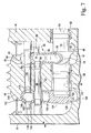
- the bore tube assembly 48 includes an annular passage 50 supplied with cooling steam from a steam supply, not shown, for flow to a plurality of radially extending tubes 54 provided in the aft disk 46. Tubes 54 communicate with circumferentially spaced, axially extending thermal medium supply tubes or passage 56 ( Figure 7) in communication with cooling passages in the first and second-stage buckets.
- Spent or returned cooling steam at an elevated temperature flows from the first and second-stage buckets through a plurality of circumferentially spaced, axially extending return tubes or passages 58 ( Figures 1 and 7).
- Return tubes 58 communicate at their aft ends with radially inwardly extending return tubes 60 ( Figure 1) in aft disk 46.
- the spent cooling steam flows into the central bore, not shown, of the bore tube assembly 48 for return to a supply or for flow to a heat recovery steam generator for use in a combined-cycle system.
- the axially extending supply and return passages 56 and 58 lie adjacent the rim of and circumferentially about the rotor, with each supply and return tube extending through axially aligned openings of the axially stacked wheels and spacers.
- the supply tube or passage 56 is illustrated passing through the opening 62 in the second-stage wheel.
- the return tube or passage 58 is illustrated in Figure 7 as passing through an opening 64 in the first spacer 30.
- Various bushings are provided at axially spaced locations within the openings of the wheels and spacers for supporting the supply and return tubes 56 and 58, respectively, in the wheels and spacers.
- each of the cooling medium supply passages 56 supplies cooling medium to a supply manifold segment, generally designated 66.
- a plurality of the circumferentially spaced supply manifold segments 66 form a supply manifold, the segments 66 being preferably located between the aft face of spacer 30 and the forward face of the second-stage wheel 16.
- each supply manifold segment is illustrated as comprising two opposed halves. It will be appreciated that the segments 66 may be provided as a unitary construction.
- a supply manifold segment 66 is provided for each supply passage 56 and, as illustrated in Figure 2, includes an arcuate rim 68 having a depending central and radially inwardly extending projection 70.
- Projection 70 has an inlet port 72 opening in an axially aft direction for connection with the cooling medium supply tube or passage 56.
- a spoolie 74 is provided to interconnect the supply tube 56 and the inlet 72 of each supply segment 66.
- the spoolies 74 comprise short tubes having spherical-shaped end portions.
- Each supply manifold segment 66 also includes a plurality of exit ports 78 and 80 along respective axially opposite end faces thereof, each in communication with a plenum 79 ( Figure 7) within the manifold segment and supplied with cooling steam via inlet 72.
- the supply manifold segment 66 has six exit ports 80 opening in an axially forward direction for supplying cooling medium to the buckets of the adjacent wheel, i.e., the buckets 22 of the first-stage wheel 14.
- the six exit ports 80 are connected via spoolies 82 with crossover tubes 84 for supplying cooling steam to the buckets of the first-stage wheel.
- Each exit port 80 thus registers axially with a passage 87 through the spacer 30 which receives the crossover tube 84.
- spoolies 86 are employed to interconnect the exit ports 78 and supply tubes, not shown, within the dovetails of the second-stage buckets 24.
- each supply manifold segment 66 includes a plurality of recesses 88, for reasons discussed below, forming an essentially sawtooth pattern along the outer margin.
- Each projection or tooth 90 of the segment 66 includes a radially outwardly extending rib 92 for engaging below a groove or recess 94 ( Figure 7) formed along an annular radially inwardly facing surface of a flange 95 about the rear face of the spacer 30.
- the engagement of the ribs 92 in the grooves or recesses 94 forms part of a retention system for maintaining the supply manifold segment 66 against substantial axial movement.
- the retention system also includes the connections between the inlet 72 and passage 56, as well as the tubular connections with the exit ports 78 and 80.
- the radial projection 70 of each segment 66 includes a radial inwardly directed flange 81 having a step with an axially directed surface 83 ( Figure 7) for engaging a flange or stop 85 on the adjacent second-stage wheel 16. This engagement also precludes substantial axial movement of segment 66 in an aft direction.
- protuberances or stops 87 ( Figure 4) project from the forward face of the supply manifold segment 66 and engage against the aft face of the spacer 30 to preclude displacement of segment 66 in a forward direction.
- the forward face of the supply manifold segment 66 also includes a projection or stop 89 having flats 91 on opposite sides thereof.
- the aft face of spacer 30 includes a linear slot 93 ( Figure 3) extending in a radial direction a distance in excess of the radial extent of projection 89.
- the side flats 91 of projection 89 engage the side walls of the slot when projection 89 is received in slot 93. This enables the manifold segment for radial movement (necessary for field assembly and disassembly) while maintaining the segment 66 against circumferential movement about the rotor.
- cooling steam supplied via axial cooling tube or passage 56 passes through inlet 72 into the plenum of the manifold segment 66 for exit through the ports 80 and 78 and delivery to the buckets 22 and 24 of the first and second stages, respectively.
- a guide vane 96 ( Figure 4) is provided centrally within the plenum to divide the flow equally among the ports 78 and 80 on opposite sides of the segment.
- the return manifold comprises a plurality of circumferentially spaced return manifold segments 100, preferably located between the forward face of spacer 30 and the aft face of the first-stage wheel 14.
- the return manifold segment 100 is illustrated as comprising two opposed halves. It will be appreciated, however, that like the supply manifold segments, the return manifold segments 100 may be provided as unitary constructions.
- each segment includes a radial, arcuate outer rim 102 and an inwardly extending projection 104, the rim 102 and projection 104 defining a plenum 106 (Figure 7).
- Each projection 104 has an exit port 108 opening in an axially aft direction for flowing return steam from the manifold segment 100 to the return tube or passageway 58 via a spoolie 110 ( Figure 6).
- each return manifold segment 100 includes a plurality of inlet ports 112 opening in an aft direction, as well as a plurality of inlet ports 114 opening in a forward direction.
- the inlet ports 114 are connected via spoolies 116 to tubes (not shown) extending from the dovetails of the buckets 22.
- Crossover tubes 118 are in communication with tubes 119 projecting forwardly from the buckets 24 of the second stage wheel 16 for delivering spent cooling steam through the inlet ports 112 into the plenum 106.
- the crossover tubes 118 extend in the recesses 88 of the supply manifold segments 66.
- the arcuate radially outer rims 102 of the return manifold segments have radially outwardly projecting ribs 120 for reception within a recess 122 formed along a radially inwardly facing annular surface of a flange 123 of the spacer 30 to retain the manifold segments against axial movement.
- the engagement of the ribs 120 in the recesses 122 forms part of a retention system for maintaining the return manifold segment 100 against substantial axial movement.
- the retention system also includes the connections between the exit port 108 and spoolie 110 as well as the tubular connections with the inlet ports 112 and 114.
- each segment 100 includes a radially inwardly directed flange 124 having a step with an axially directed surface 126 (Figure 7) for engaging an aft face portion or stop 128 of the first-stage wheel 14. This engagement also precludes substantial axial movement of segment 100 in a forward direction. Still further, protuberances or stops 129 ( Figure 5) project from the aft face of the return manifold segment 100 and engage against the forward face of the spacer 30 to preclude the displacement of segment 100 in an aft direction.
- the aft face of the return manifold segment 100 also includes a projection 132 having flats 134 on opposite sides thereof similarly as the projection 89 of the supply manifold segment 66.
- the forward face of spacer 30 includes a linear slot 136 ( Figure 6) extending in a radial direction a distance in excess of the radial extent of projection 132.
- the flats 134 of projection 132 and the side walls of the slots when projection 132 is received in slot 136 enable the return manifold segment 100 for radial movement (necessary for field assembly and disassembly) while maintaining the segment 100 against circumferential movement about the rotor.
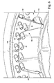
- the supply and return manifold segments are circumferentially staggered relative to one another.
- the juncture of the wings or legs 103 of adjacent return manifold segment 100 lie axially opposite the projecting portion 70 of a supply manifold segment 66.
- the four inner exit ports 80 lie in axial alignment at a radial location inwardly of the wings or legs 103 of the adjacent return manifold segments.
- pairs of the crossover tubes 84 from a supply manifold segment 66 extend axially below the wings or legs 103 of circumferentially adjacent return manifold segments 100.
- the latter segments 100 also have a pair of openings 105 passing centrally through the projection 104. These openings are closed relative to the plenum 106 and receive the crossover tubes 84 at the ends of circumferentially adjoining supply manifold segments.
- a plurality of guide vanes are provided.
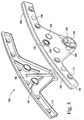
- a central guide vane 140 ( Figure 5) is provided along the forward wall of the segment 100 for substantially precluding mixing the flows from the inlet ports on opposite sides of the segments.
- Additional guide vanes 142 having sections angularly related to one another guide the return steam toward the exit port 108 on each side of guide vane 140 with minimal pressure losses.
- guide vanes 144 are provided in quadrants in the exit port 108, the guide vanes 144 terminating short of the centerline of the outlet port 108. Consequently, the swirling effect otherwise encountered in the steam as the steam flows into and from the return manifold segments is substantially reduced or eliminated so that minimal pressure losses occur.
- each of the supply and return manifold segments can be integrally cast or may be formed of sections welded to one another, as illustrated in Figures 2 and 5.
Landscapes
- Engineering & Computer Science (AREA)
- Mechanical Engineering (AREA)
- General Engineering & Computer Science (AREA)
- Turbine Rotor Nozzle Sealing (AREA)
Applications Claiming Priority (2)
| Application Number | Priority Date | Filing Date | Title |
|---|---|---|---|
| US984826 | 1997-12-04 | ||
| US09/984,826 US6506021B1 (en) | 2001-10-31 | 2001-10-31 | Cooling system for a gas turbine |
Publications (2)
| Publication Number | Publication Date |
|---|---|
| EP1308600A1 true EP1308600A1 (de) | 2003-05-07 |
| EP1308600B1 EP1308600B1 (de) | 2009-03-04 |
Family
ID=25530920
Family Applications (1)
| Application Number | Title | Priority Date | Filing Date |
|---|---|---|---|
| EP02257513A Expired - Lifetime EP1308600B1 (de) | 2001-10-31 | 2002-10-30 | Kühlsystem für eine Gasturbine |
Country Status (6)
| Country | Link |
|---|---|
| US (1) | US6506021B1 (de) |
| EP (1) | EP1308600B1 (de) |
| JP (1) | JP4293417B2 (de) |
| KR (1) | KR100901908B1 (de) |
| CN (1) | CN1298978C (de) |
| RU (1) | RU2303138C2 (de) |
Families Citing this family (15)
| Publication number | Priority date | Publication date | Assignee | Title |
|---|---|---|---|---|
| CN1302201C (zh) * | 2003-07-16 | 2007-02-28 | 沈阳黎明航空发动机(集团)有限责任公司 | 一种重型燃气轮机 |
| US7344354B2 (en) * | 2005-09-08 | 2008-03-18 | General Electric Company | Methods and apparatus for operating gas turbine engines |
| FR2931873B1 (fr) * | 2008-05-29 | 2010-08-20 | Snecma | Ensemble d'un disque de turbine d'un moteur a turbine a gaz et d'un tourillon support de palier,circuit de refroidissement d'un disque de turbine d'un tel ensemble. |
| US8061971B2 (en) * | 2008-09-12 | 2011-11-22 | General Electric Company | Apparatus and method for cooling a turbine |
| JP5546876B2 (ja) * | 2009-01-16 | 2014-07-09 | 株式会社東芝 | 蒸気タービン |
| RU2406844C1 (ru) * | 2009-04-09 | 2010-12-20 | Магомет Бузигитович Тетуев | Двигатель внутреннего сгорания |
| US8267649B2 (en) * | 2009-05-15 | 2012-09-18 | General Electric Company | Coupling for rotary components |
| WO2011117730A2 (en) * | 2010-03-26 | 2011-09-29 | Philip Morris Products S.A. | Liquid dispensing system for use in the formation of a tobacco pouch product |
| RU2539404C2 (ru) * | 2010-11-29 | 2015-01-20 | Альстом Текнолоджи Лтд | Осевая газовая турбина |
| EP2508713A1 (de) | 2011-04-04 | 2012-10-10 | Siemens Aktiengesellschaft | Gasturbine mit einem Wärmeschild sowie Betriebsverfahren |
| US10378379B2 (en) | 2015-08-27 | 2019-08-13 | General Electric Company | Gas turbine engine cooling air manifolds with spoolies |
| KR101663306B1 (ko) * | 2015-10-02 | 2016-10-06 | 두산중공업 주식회사 | 가스터빈 디스크 |
| US10443620B2 (en) * | 2018-01-02 | 2019-10-15 | General Electric Company | Heat dissipation system for electric aircraft engine |
| CN111894734A (zh) * | 2020-08-12 | 2020-11-06 | 哈电发电设备国家工程研究中心有限公司 | 一种中小燃气轮机的透平机及工作方法 |
| CN113882954A (zh) * | 2021-09-17 | 2022-01-04 | 北京动力机械研究所 | 一种低流阻分流装置 |
Citations (6)
| Publication number | Priority date | Publication date | Assignee | Title |
|---|---|---|---|---|
| US5232335A (en) * | 1991-10-30 | 1993-08-03 | General Electric Company | Interstage thermal shield retention system |
| US5343694A (en) * | 1991-07-22 | 1994-09-06 | General Electric Company | Turbine nozzle support |
| US5472313A (en) * | 1991-10-30 | 1995-12-05 | General Electric Company | Turbine disk cooling system |
| EP0909878A2 (de) * | 1997-10-17 | 1999-04-21 | Hitachi, Ltd. | Gasturbine |
| US6053697A (en) * | 1998-06-26 | 2000-04-25 | General Electric Company | Trilobe mounting with anti-rotation apparatus for an air duct in a gas turbine rotor |
| EP1101897A2 (de) * | 1999-11-17 | 2001-05-23 | General Electric Company | Methode zur Demontage, zum Ersatz und zur Montage von Teilen eines Dampfkühlungssystems für Gasturbinen |
Family Cites Families (9)
| Publication number | Priority date | Publication date | Assignee | Title |
|---|---|---|---|---|
| US3291447A (en) * | 1965-02-15 | 1966-12-13 | Gen Electric | Steam turbine rotor cooling |
| US4118136A (en) * | 1977-06-03 | 1978-10-03 | General Electric Company | Apparatus for attaching tubing to a rotating disk |
| SU1132613A1 (ru) * | 1982-10-29 | 1996-04-10 | Производственное объединение "Турбомоторный завод" | Охлаждаемый ротор турбомашины |
| SU1749492A1 (ru) * | 1988-07-07 | 1992-07-23 | Институт технической теплофизики АН УССР | Ротор газовой турбины |
| US5322335A (en) * | 1993-08-30 | 1994-06-21 | Penda Corporation | Automotive floor liner |
| US5593274A (en) | 1995-03-31 | 1997-01-14 | General Electric Co. | Closed or open circuit cooling of turbine rotor components |
| US6053701A (en) * | 1997-01-23 | 2000-04-25 | Mitsubishi Heavy Industries, Ltd. | Gas turbine rotor for steam cooling |
| JPH11153301A (ja) * | 1997-11-25 | 1999-06-08 | Mitsubishi Heavy Ind Ltd | 脱気器スプレイノズル |
| JP2001152804A (ja) * | 1999-11-19 | 2001-06-05 | Mitsubishi Heavy Ind Ltd | ガスタービン設備及びタービン翼 |
-
2001
- 2001-10-31 US US09/984,826 patent/US6506021B1/en not_active Expired - Fee Related
-
2002
- 2002-10-30 JP JP2002315181A patent/JP4293417B2/ja not_active Expired - Fee Related
- 2002-10-30 KR KR1020020066519A patent/KR100901908B1/ko not_active Expired - Fee Related
- 2002-10-30 RU RU2002129119/06A patent/RU2303138C2/ru not_active IP Right Cessation
- 2002-10-30 EP EP02257513A patent/EP1308600B1/de not_active Expired - Lifetime
- 2002-10-31 CN CNB021482950A patent/CN1298978C/zh not_active Expired - Fee Related
Patent Citations (6)
| Publication number | Priority date | Publication date | Assignee | Title |
|---|---|---|---|---|
| US5343694A (en) * | 1991-07-22 | 1994-09-06 | General Electric Company | Turbine nozzle support |
| US5232335A (en) * | 1991-10-30 | 1993-08-03 | General Electric Company | Interstage thermal shield retention system |
| US5472313A (en) * | 1991-10-30 | 1995-12-05 | General Electric Company | Turbine disk cooling system |
| EP0909878A2 (de) * | 1997-10-17 | 1999-04-21 | Hitachi, Ltd. | Gasturbine |
| US6053697A (en) * | 1998-06-26 | 2000-04-25 | General Electric Company | Trilobe mounting with anti-rotation apparatus for an air duct in a gas turbine rotor |
| EP1101897A2 (de) * | 1999-11-17 | 2001-05-23 | General Electric Company | Methode zur Demontage, zum Ersatz und zur Montage von Teilen eines Dampfkühlungssystems für Gasturbinen |
Also Published As
| Publication number | Publication date |
|---|---|
| CN1298978C (zh) | 2007-02-07 |
| KR20030036049A (ko) | 2003-05-09 |
| JP4293417B2 (ja) | 2009-07-08 |
| CN1417462A (zh) | 2003-05-14 |
| US6506021B1 (en) | 2003-01-14 |
| KR100901908B1 (ko) | 2009-06-10 |
| JP2003184502A (ja) | 2003-07-03 |
| EP1308600B1 (de) | 2009-03-04 |
| RU2303138C2 (ru) | 2007-07-20 |
Similar Documents
| Publication | Publication Date | Title |
|---|---|---|
| EP1308600B1 (de) | Kühlsystem für eine Gasturbine | |
| US8529195B2 (en) | Inducer for gas turbine system | |
| JP3725930B2 (ja) | タービン | |
| EP0698724B1 (de) | Kühlkreislauf des abströmendes einer Turbinenleitschaufel | |
| EP0768448B1 (de) | Gekühlte Schaufeln für ein Turbinenleitgitter | |
| EP1079069B1 (de) | Dampfkühlungssystem für eine Gasturbine | |
| JP4509277B2 (ja) | ロータ中孔及びタービン・ロータ・ホイール/スペーサ熱交換流れ回路 | |
| JP6779651B2 (ja) | 燃料ノズルを有するシステムおよび方法 | |
| EP1101897B1 (de) | Methode zur Demontage, zum Ersatz und zur Montage von Teilen eines Dampfkühlungssystems für Gasturbinen | |
| EP0757159B1 (de) | Kühlung einer Leitschaufel | |
| EP0161560A1 (de) | Gasgekühltes Eintrittsgehäuse für eine Radialturbine | |
| EP4001593B1 (de) | Eine gasturbinenleitschaufel mit einer prallgekühlten innenplattform | |
| EP3456925B1 (de) | Struktur zur kühlung von turbinenschaufeln, zugehörige turbine und gasturbine | |
| EP4047190B1 (de) | Ringsegment und turbomaschine | |
| CN106988802A (zh) | 叶轮空间吹扫流混合腔室 | |
| JP2017150489A (ja) | ロータホイール及びインペラインサート | |
| EP3388635B1 (de) | Halter für eine laufschaufel, zugehörige turbineneinheit und gasturbine | |
| US20230366327A1 (en) | Ring segment and turbomachine including same | |
| KR102010660B1 (ko) | 가스 터빈 | |
| CZ20003081A3 (cs) | Parní chladicí systém pro plynovou turbínu |
Legal Events
| Date | Code | Title | Description |
|---|---|---|---|
| PUAI | Public reference made under article 153(3) epc to a published international application that has entered the european phase |
Free format text: ORIGINAL CODE: 0009012 |
|
| AK | Designated contracting states |
Designated state(s): AT BE BG CH CY CZ DE DK EE ES FI FR GB GR IE IT LI LU MC NL PT SE SK TR |
|
| AX | Request for extension of the european patent |
Extension state: AL LT LV MK RO SI |
|
| RIN1 | Information on inventor provided before grant (corrected) |
Inventor name: BYLINA, NOEL JACOB Inventor name: WILSON, IAN DAVID Inventor name: SALAMAH, SAMIR ARMANDO |
|
| 17P | Request for examination filed |
Effective date: 20031107 |
|
| AKX | Designation fees paid |
Designated state(s): FR GB |
|
| REG | Reference to a national code |
Ref country code: DE Ref legal event code: 8566 |
|
| 17Q | First examination report despatched |
Effective date: 20050415 |
|
| GRAP | Despatch of communication of intention to grant a patent |
Free format text: ORIGINAL CODE: EPIDOSNIGR1 |
|
| GRAS | Grant fee paid |
Free format text: ORIGINAL CODE: EPIDOSNIGR3 |
|
| GRAA | (expected) grant |
Free format text: ORIGINAL CODE: 0009210 |
|
| AK | Designated contracting states |
Kind code of ref document: B1 Designated state(s): FR GB |
|
| REG | Reference to a national code |
Ref country code: GB Ref legal event code: FG4D |
|
| PLBE | No opposition filed within time limit |
Free format text: ORIGINAL CODE: 0009261 |
|
| STAA | Information on the status of an ep patent application or granted ep patent |
Free format text: STATUS: NO OPPOSITION FILED WITHIN TIME LIMIT |
|
| 26N | No opposition filed |
Effective date: 20091207 |
|
| PGFP | Annual fee paid to national office [announced via postgrant information from national office to epo] |
Ref country code: FR Payment date: 20131017 Year of fee payment: 12 Ref country code: GB Payment date: 20131028 Year of fee payment: 12 |
|
| GBPC | Gb: european patent ceased through non-payment of renewal fee |
Effective date: 20141030 |
|
| PG25 | Lapsed in a contracting state [announced via postgrant information from national office to epo] |
Ref country code: GB Free format text: LAPSE BECAUSE OF NON-PAYMENT OF DUE FEES Effective date: 20141030 |
|
| REG | Reference to a national code |
Ref country code: FR Ref legal event code: ST Effective date: 20150630 |
|
| PG25 | Lapsed in a contracting state [announced via postgrant information from national office to epo] |
Ref country code: FR Free format text: LAPSE BECAUSE OF NON-PAYMENT OF DUE FEES Effective date: 20141031 |