EP1308593A2 - Junction of a wire channel between a door wing and a door frame - Google Patents
Junction of a wire channel between a door wing and a door frame Download PDFInfo
- Publication number
- EP1308593A2 EP1308593A2 EP02019685A EP02019685A EP1308593A2 EP 1308593 A2 EP1308593 A2 EP 1308593A2 EP 02019685 A EP02019685 A EP 02019685A EP 02019685 A EP02019685 A EP 02019685A EP 1308593 A2 EP1308593 A2 EP 1308593A2
- Authority
- EP
- European Patent Office
- Prior art keywords
- cable
- cable duct
- duct transition
- door
- guide sleeve
- Prior art date
- Legal status (The legal status is an assumption and is not a legal conclusion. Google has not performed a legal analysis and makes no representation as to the accuracy of the status listed.)
- Withdrawn
Links
- 230000007704 transition Effects 0.000 claims description 120
- 230000002093 peripheral effect Effects 0.000 claims description 24
- 238000007789 sealing Methods 0.000 claims description 5
- 239000002184 metal Substances 0.000 description 8
- 230000006978 adaptation Effects 0.000 description 2
- 238000003801 milling Methods 0.000 description 2
- 230000003287 optical effect Effects 0.000 description 2
- 235000014676 Phragmites communis Nutrition 0.000 description 1
- 238000010586 diagram Methods 0.000 description 1
- 238000010616 electrical installation Methods 0.000 description 1
- 238000003780 insertion Methods 0.000 description 1
- 230000037431 insertion Effects 0.000 description 1
- 230000010354 integration Effects 0.000 description 1
- 239000000463 material Substances 0.000 description 1
- 230000035515 penetration Effects 0.000 description 1
- 238000009420 retrofitting Methods 0.000 description 1
- 239000000126 substance Substances 0.000 description 1
- 230000000007 visual effect Effects 0.000 description 1
- XLYOFNOQVPJJNP-UHFFFAOYSA-N water Substances O XLYOFNOQVPJJNP-UHFFFAOYSA-N 0.000 description 1
Images


Classifications
-
- E—FIXED CONSTRUCTIONS
- E05—LOCKS; KEYS; WINDOW OR DOOR FITTINGS; SAFES
- E05D—HINGES OR SUSPENSION DEVICES FOR DOORS, WINDOWS OR WINGS
- E05D11/00—Additional features or accessories of hinges
- E05D11/0081—Additional features or accessories of hinges for transmitting energy, e.g. electrical cable routing
-
- E—FIXED CONSTRUCTIONS
- E05—LOCKS; KEYS; WINDOW OR DOOR FITTINGS; SAFES
- E05Y—INDEXING SCHEME ASSOCIATED WITH SUBCLASSES E05D AND E05F, RELATING TO CONSTRUCTION ELEMENTS, ELECTRIC CONTROL, POWER SUPPLY, POWER SIGNAL OR TRANSMISSION, USER INTERFACES, MOUNTING OR COUPLING, DETAILS, ACCESSORIES, AUXILIARY OPERATIONS NOT OTHERWISE PROVIDED FOR, APPLICATION THEREOF
- E05Y2900/00—Application of doors, windows, wings or fittings thereof
- E05Y2900/10—Application of doors, windows, wings or fittings thereof for buildings or parts thereof
- E05Y2900/13—Type of wing
- E05Y2900/132—Doors
Definitions
- the invention relates to a cable duct transition between a door leaf and a door frame, with a first Cable duct transition part, which is fixed to the door frame is, and a second cable duct transition part, which is firmly on Door leaf arranged and in relation to the door frame fixed first Cable duct transition part is movable.
- Such a cable duct transition serves to remove a cable from the To transfer the door leaf to the door frame, which on the one hand Door-side electrical devices, for example an electrical block lock, bolt switch or reed contacts, Escape door opener etc. connected and on the other hand with a frame-side power source is connected.
- Door-side electrical devices for example an electrical block lock, bolt switch or reed contacts, Escape door opener etc. connected and on the other hand with a frame-side power source is connected.
- the invention has for its object a cable duct transition between a door leaf and a door frame create the both closed and open Door can be made virtually invisible and its Assembly considerably simplified compared to the prior art is.
- the first cable duct transition part, which is fixed to the door frame, and the door leaf fixed second cable duct transition part in a door leaf Door hinge pivot bearing mounted on the door frame integrated and around a pivot axis of the hinge pivot bearing are rotatable to each other.
- the rotatable design of the doorframe-proof first cable duct transition part and of the door leaf-fixed second cable duct transition part Consequence that a mutual rotation of the two cable duct transition parts to the maximum swivel angle of the door leaf is limited in relation to the door frame.
- Cable duct transition has the door cable fixed first cable duct transition part one coaxial to the pivot axis of the door hinge pivot bearing arranged cable guide sleeve and the door wing fixed second cable duct transition part a coaxial to Pivot axis of the door hinge pivot bearing arranged cable guide sleeve on, with the two cable guide sleeves towards the pivot axis of the door hinge pivot bearing next to each other arranged and about the pivot axis of the hinge pivot bearing are rotatable to each other.
- the door frame fixed first cable duct transition part advantageous a cable entry socket, through which a cable from the door frame into the cable guide sleeve of the door frame fixed first cable duct transition part is feasible.
- the cable entry socket of the door frame is expedient first cable duct transition part perpendicular to the swivel axis the hinge pivot bearing arranged.
- the door wing fixed second cable duct transition part a cable entry socket has through which a cable from the door leaf in the cable guide sleeve of the door leaf-fixed second cable duct transition part is feasible. With this configuration is achievable that the electrical cable or one as such visible sheathing of the cable between the door frame and door leaf remains invisible.
- the cable entry socket of the door cable-fixed second cable duct transition part is expediently perpendicular to Pivot axis of the hinge pivot bearing arranged.
- one of the two cable guide sleeves on the other adjacent end section an inner radial step and the other of the two cable guide sleeves on their one adjacent End portion has an outer radial step, wherein the cable guide sleeve provided with the outer radial step with its end section in the one with the inner radial step provided cable guide sleeve is inserted.
- the cable guide sleeve provided with the outer radial step with its end section in the one with the inner radial step provided cable guide sleeve is inserted.
- a first O-sealing ring is arranged between the inner peripheral surface of the with the inner Radial stage formed end portion of a cable guide sleeve and the outer peripheral surface of the with the outer Radial stage formed end portion of the other cable guide sleeve.
- Cable duct transition is at the upper end of the door hinge pivot bearing arranged.
- Easy retrofitting already existing hinge pivot bearings with the invention Cable duct transition can be reached if the Transition between the hinge pivot bearing and the cable duct transition is formed by a pin head, the Pin section in a recess of the pivot axis of the Inserted hinge pivot bearing forming pivot is and for that about the hinge pivot bearing in upward
- the cable guide sleeve in the direction of the projecting head section of the lower cable duct transition part is rotatably arranged is.
- a second O-sealing ring is arranged.
- a material, color and shape adjustment of the Cable duct transition according to the invention to the existing hinge pivot mounting is with a comparatively low Effort attainable if on the outer peripheral surface of the upper one Cable guide sleeve sits an upper cover sleeve that itself over the lower cable guide sleeve to the cable entry socket of the lower cable duct transition part and one the cable entry socket of the upper cable duct transition part has assigned longitudinal slot.
- Such a cover sleeve can be optically large with little effort Design adaptation to the existing hinge pivot bearing, whereby they are assigned due to the upper cable entry connector Longitudinal slot in a simple manner via the upper cable guide sleeve can be pushed until it is with its lower edge against the lower cable entry connector of the cable duct transition encounters.
- a lower cover sleeve be provided, extending to the bottom of the top Cover sleeve or to the top of the cable entry socket of the extends lower cable duct transition part and one of the cable entry pipe assigned to the lower cable duct transition part Has longitudinal slot.
- Cable duct transition align the outer peripheral surfaces the upper cover sleeve and the lower cover sleeve with each other and with the outer peripheral surfaces of hinge sleeves the hinge pivot bearing.
- Cable duct transition 1 forms in the shown Embodiment a technical-constructive unit with a door hinge pivot bearing 2, by means of which in the Figures 1 to 3 door wing, not shown, on one in the figures 1 to 3 door frame, also not shown, by one in Figure 3 by a dash-dotted line pivot axis 3 is pivotally mounted.
- the pivot axis 3 belongs to the hinge pivot bearing forming pivot pin 4, around which a hinge sleeve 5 a door hinge 6 on the door frame and an upper one Hinge sleeve 7 and a lower hinge sleeve 8 one Door hinge-side hinge 9 coaxial and rotatable to each other are stored.
- this is at the upper end of the door hinge pivot bearing 2 provided and it has an upper, door cable-resistant first cable duct transition part 10 and a lower, second cable duct transition part 11 that is fixed to the door wing on.
- pivot pin head 12 Between the lower, door leaf-fixed second cable duct transition part 11 and the upper end of the pivot axis 3 of the Door hinge pivot bearing 2 forming pivot pin 4 is in the shown a pin head 12, the one with a pin section 13 in one in the upper end section of the pivot pin 4 centrally formed recess 14 sits.
- a head portion 15 of the pin head 12 sits on the top End face of the pivot pin 4 and protrudes in the axial direction via the upper hinge sleeve 7 of the door hinge-side hinge 9 before.
- the lower, door leaf-fixed second cable duct transition part 11 has a cable guide sleeve 16 which is coaxial to the pivot pin 4 of the hinge pivot bearing 2 is arranged and with it lower face against the upper face of the upper Hinge sleeve 7 of the door leaf-side hinge 9 abuts and with its lower end portion, the inside diameter of which Corresponds to the outer diameter of the head section 15 of the pin head 12, arranged around the head portion 15 of the pin head 12 is.
- the lower cable guide sleeve 16 has a radial or perpendicular to the pivot axis 3 of the hinge pivot bearing 2 arranged cable entry socket 17, through the one Cable, which electrical equipment in the area of the door leaf, not shown, is assigned to the figures, from the door wing into the cable guide sleeve 16 of the lower door wing fixed second cable duct transition part 11 in or is transferable.
- the lower cable guide sleeve 16 has in the area of its upper one End portion formed on its inner peripheral surface inner radial stage 18.
- the upper cable guide sleeve 19 is in the area of its lower End portion on its outer peripheral surface with an outer Radial stage 21 formed.
- the dimensions of the inner radial step 18 of the lower cable guide sleeve 16 and the outer radial stage 21 of the upper Cable guide sleeve 19 are chosen so that the lower end portion the upper cable guide sleeve 19 with its outer peripheral surface against the inner peripheral surface of the upper end portion the lower cable guide sleeve 16 abuts.
- the upper Cable guide sleeve 19 and the lower cable guide sleeve 16 are to each other about the pivot axis 3 of the hinge pivot bearing 2 rotatable.
- the cable that is in the Cable duct transition 1 between door leaf and door frame the cable entry socket 17 of the lower door wing fixed second cable duct transition part 11, through the lower cable guide sleeve 16 of the same, the upper cable guide sleeve 19 of the upper part of the cable duct that is fixed to the door frame 10 and its cable inlet connector 20 is guided at Opening the door wing of a torsion or twist load subjected, resulting from the opening angle of the door leaf in relation to the door frame and accordingly the maximum possible opening angle of the door leaf in relation is limited to the door frame.
- the one formed by the cable duct transition part 1, the overpass of the cable, not shown in the figures, between Door frame and door wing cavity is against that Penetration of foreign bodies, moisture etc. protected, and through a first O-sealing ring 22, which between the Inner peripheral surface of the upper end portion of the lower cable guide sleeve 16 and the outer peripheral surface of the end portion the lower cable guide sleeve 19 is arranged, a second O-seal ring 23 which is between the outer peripheral surface the head portion 15 of the pin head 12 and the Inner peripheral surface of the lower end portion of the lower cable guide sleeve 16 is arranged, and by a cover cap 24 through which the upper end of the upper cable guide sleeve 19 is closed.
- an upper cover sleeve 25 is provided from the cap 24 or the upper end of the upper Cable guide sleeve 19 of the upper, door frame-fixed first cable duct transition part 10 over the upper cable guide sleeve 19 and the lower cable guide sleeve 16 to the upper end of the cable entry socket 17 of the lower door wing fixed second cable duct transition part 11 extends.
- the top cover sleeve 25 is formed with a longitudinal slot 26, the the cable entry socket 20 of the upper, door frame fixed first Cable duct transition part 10 is assigned.
- This lower one Cover sleeve 27 extends from the area of the upper End of the cable entry socket 17 of the lower, door leaf-fixed second cable duct transition part 11 to the lower end the lower cable guide sleeve 16 of the lower, door leaf fixed second cable duct transition part 11.
- This lower cover sleeve 27 has a longitudinal slot 28 which connects the cable entry 17 of the lower, door wing-fixed second cable duct transition part 11 is assigned.
- the upper cover sleeve 25 and the lower cover sleeve 27 of the cable duct transition 1 is an embodiment of the same reached, in whose outer peripheral surface with the outer peripheral surface the hinge sleeves 5, 7, 8 of the door hinge pivot bearing 2 is aligned.
- the above Cable duct transition 1 is an invisible transition of a Cable between a door frame and a door leaf possible. Due to the adapted design of the cable duct transition 1 to the hinge pivot mounting 2 is achieved that no evidence whatsoever of the existence of any between the Door frame and the cable running through the door leaf are visible.
Landscapes
- Engineering & Computer Science (AREA)
- Mechanical Engineering (AREA)
- Electric Cable Arrangement Between Relatively Moving Parts (AREA)
Abstract
Description
Die Erfindung bezieht sich auf einen Kabelkanalübergang zwischen einem Türflügel und einer Türzarge, mit einem ersten Kabelkanalübergangsteil, das fest an der Türzarge angeordnet ist, und einem zweiten Kabelkanalübergangsteil, das fest am Türflügel angeordnet und in bezug auf das türzargenfeste erste Kabelkanalübergangsteil bewegbar ist.The invention relates to a cable duct transition between a door leaf and a door frame, with a first Cable duct transition part, which is fixed to the door frame is, and a second cable duct transition part, which is firmly on Door leaf arranged and in relation to the door frame fixed first Cable duct transition part is movable.
Ein derartiger Kabelkanalübergang dient dazu, ein Kabel vom Türflügel zur Türzarge überzuleiten, welches einerseits an türflügelseitige elektrische Einrichtungen, beispielsweise ein elektrisches Blockschloß, Riegelschalt- bzw. Reedkontakte, Fluchttüröffner etc. angeschlossen und andererseits mit einer zargenseitigen Stromquelle in Verbindung steht.Such a cable duct transition serves to remove a cable from the To transfer the door leaf to the door frame, which on the one hand Door-side electrical devices, for example an electrical block lock, bolt switch or reed contacts, Escape door opener etc. connected and on the other hand with a frame-side power source is connected.
Es sind Kabelkanalübergänge bekannt, bei dem ein türflügelseitiger Kabelausgang mittels eines flexiblen Metallschlauchs mit einem band- bzw. zargenseitigen Kabelausgang verbunden ist. Durch den türflügelseitigen Kabelausgang wird das elektrische Kabel in den flexiblen Metallschlauch hinein geführt, den es am anderen Ende desselben durch den wand- bzw. zargenseitigen Kabelausgang wieder verläßt. Zwischen den beiden Kabelausgängen ist der Metallschlauch von einer Seite der Tür her sichtbar, was selbstverständlich auch für die beiden Kabelausgänge gilt. Abgesehen davon, daß sich hier eine Störung des ästhetischen Gesamteindrucks der Tür ergibt, besteht insoweit eine erhöhte Manipulationsgefahr, als durch einfaches Durchschneiden des das Kabel enthaltenen flexiblen Metallschlauchs die Stromzuführung an die im Türflügel vorgesehenen elektrischen Einrichtungen unterbrochen werden kann.Cable channel transitions are known in which a door wing side Cable exit using a flexible metal hose connected to a hinge or frame side cable outlet is. The electrical Cables lead into the flexible metal hose, which is at the other end of the same through the wall or frame side Leaves cable exit again. Between the two cable exits is the metal hose from one side of the door visible, which of course also applies to the two cable outlets applies. Apart from the fact that there is a disturbance here the overall aesthetic impression of the door an increased risk of manipulation than by simple Cut through the flexible metal hose containing the cable the power supply to those provided in the door leaf electrical equipment can be interrupted.
Des weiteren ist ein verdeckt liegender Kanalübergang aus dem Stand der Technik bekannt, bei dem ein Kabelaustritt in der Türfalz und ein Kabelaustritt in der dieser bei geschlossener Tür gegenüberliegenden Zargenaußenfläche angeordnet ist. Zwischen den beiden Kabelaustritten ist eine flexible Hohlmetallspirale angeordnet, durch die das Kabel zwischen den beiden Kabelaustritten geführt wird. Bei geschlossener Tür liegen die Türfalz und die entsprechende Zargenfläche aneinander an, so daß der Kabelkanalübergang nicht sichtbar ist. Bei geöffneter Tür ist der vorstehend geschilderte Kabelkanalübergang sichtbar, wobei dann durch einfaches Durchschneiden der Hohlmetallspirale eine Unterbrechung der Stromzufuhr zu den türflügelseitigen elektrischen Einrichtungen ohne weiteres möglich ist. Die letztgenannte Variante eines bei geschlossener Tür verdeckt liegenden Kabelkanalübergangs erfordert einen vergleichsweise hohen Platzbedarf im Türfalzbereich. Bei der Erstellung der Fräsungen im Türflügel bzw. in der Türzarge ergibt sich ein beträchtlich erhöhter Arbeitsaufwand, wie auch bei der Montage des Kabelkanalübergangs sowohl beim Türenhersteller als auch bei der Elektroinstallation bei der Montage der Tür. Abgesehen davon wird bei Realisierung dieses Kabelkanalübergangs die Tür- bzw. die Zargengeometrie durch die erforderlichen Einfräsungen nicht unerheblich geschwächt, was insbesondere bei Sicherheitstüren in hohem Maße unerwünscht ist. Insgesamt ergibt sich eine vergleichsweise aufwendige Montage aufgrund der Vielzahl von Einzelteilen.Furthermore there is a concealed channel transition from the State of the art in which a cable outlet in the Door rebate and a cable outlet in this when closed Door is located opposite the outside of the frame. Between The two cable exits are a flexible hollow metal spiral arranged through which the cable between the two Cable exits are performed. Lie with the door closed the door rebate and the corresponding frame surface together so that the cable duct transition is not visible. When open The door is the cable duct transition described above visible, then by simply cutting through the Hollow metal spiral an interruption in the power supply to the electrical equipment on the door leaf without further ado is possible. The latter variant of a closed Door concealed cable duct transition requires one comparatively high space requirement in the door rebate area. at the creation of the millings in the door leaf or in the door frame there is a considerably increased amount of work, such as also when installing the cable duct transition at the door manufacturer as well as the electrical installation at the Assembling the door. Apart from that, when realizing this Cable channel transition through the door or frame geometry the necessary milling not significantly weakened, which is highly undesirable, particularly with security doors is. Overall, there is a comparatively complex Assembly due to the large number of individual parts.
Der Erfindung liegt die Aufgabe zugrunde, einen Kabelkanalübergang zwischen einem Türflügel und einer Türzarge zu schaffen, der sowohl bei geschlossener als auch bei geöffneter Tür quasi unsichtbar gestaltet werden kann und dessen Montage im Vergleich zum Stand der Technik erheblich vereinfacht ist.The invention has for its object a cable duct transition between a door leaf and a door frame create the both closed and open Door can be made virtually invisible and its Assembly considerably simplified compared to the prior art is.
Diese Aufgabe wird erfindungsgemäß dadurch gelöst, daß das türzargenfeste erste Kabelkanalübergangsteil und das türflügelfeste zweite Kabelkanalübergangsteil in eine den Türflügel schwenkbar an der Türzarge lagernde Türbandschwenklagerung integriert und um eine Schwenkachse der Türbandschwenklagerung zueinander drehbar sind. Durch die Integration des Kabelkanalübergangs in die Türbandschwenklagerung ist für Außenstehende praktisch nicht erkennbar, daß überhaupt eine elektrische Kabelverbindung zwischen der Türzarge und dem Türflügel vorhanden ist. Die zueinander drehbare Ausgestaltung des türzargenfesten ersten Kabelkanalübergangsteils und des türflügelfesten zweiten Kabelkanalübergangsteils hat zur Folge, daß eine gegenseitige Verdrehung der beiden Kabelkanalübergangsteile auf den maximalen Schwenkwinkel des Türflügels in bezug auf die Türzarge beschränkt ist. Hierdurch kann die Torsionsbelastung eines durch den erfindungsgemäßen Kabelkanalübergang geführten elektrischen Kabels entsprechend reduziert werden, wobei sich in Versuchen herausgestellt hat, daß ein elektrisches Kabel ohne weiteres eine halbe Million Öffnungsspiele des Türflügels übersteht, ohne daß irgendwelcher Verschleiß des elektrischen Kabels aufgetreten wäre. Ein flexibler Metallschlauch oder eine flexible Hohlmetallspirale ist im Falle des erfindungsgemäßen Kabelkanalübergangs nicht vorhanden, so daß ein vergleichsweise wenig aufwendiges Durchtrennen des elektrischen Kabels im Falle des erfindungsgemäßen Kabelkanalübergangs nicht möglich ist. Durch die Integration des erfindungsgemäßen Kabelkanalübergangs in die bei jeder Tür ohnehin erforderliche Türbandschwenklagerung wird darüber hinaus der ästhetische Gesamteindruck der Tür nicht spürbar beeinflußt.This object is achieved in that the The first cable duct transition part, which is fixed to the door frame, and the door leaf fixed second cable duct transition part in a door leaf Door hinge pivot bearing mounted on the door frame integrated and around a pivot axis of the hinge pivot bearing are rotatable to each other. By integrating the cable duct transition is in the door hinge pivot bearing for outsiders practically not recognizable that at all electrical cable connection between the door frame and the Door leaf is present. The rotatable design of the doorframe-proof first cable duct transition part and of the door leaf-fixed second cable duct transition part Consequence that a mutual rotation of the two cable duct transition parts to the maximum swivel angle of the door leaf is limited in relation to the door frame. This can the torsional load of a cable duct transition according to the invention guided electrical cable accordingly be reduced, whereby it has been found in tests that an electrical cable easily half a million Opening games of the door wing survives without any Wear of the electrical cable would have occurred. On flexible metal hose or a flexible hollow metal spiral is not in the case of the cable duct transition according to the invention available, so that a comparatively little effort Cutting the electrical cable in the case of the invention Cable duct transition is not possible. Through integration of the cable duct transition according to the invention in the door hinge swivel mounting required for every door is also the overall aesthetic impression of the door not noticeably affected.
Gemäß einer vorteilhaften Ausgestaltung des erfindungsgemäßen Kabelkanalübergangs weist das türzargenfeste erste Kabelkanalübergangsteil eine koaxial zur Schwenkachse der Türbandschwenklagerung angeordnete Kabelführungshülse und das türflügelfeste zweite Kabelkanalübergangsteil eine koaxial zur Schwenkachse der Türbandschwenklagerung angeordnete Kabelführungshülse auf, wobei die beiden Kabelführungshülsen in Richtung der Schwenkachse der Türbandschwenklagerung nebeneinander angeordnet und um die Schwenkachse der Türbandschwenklagerung zueinander drehbar sind.According to an advantageous embodiment of the invention Cable duct transition has the door cable fixed first cable duct transition part one coaxial to the pivot axis of the door hinge pivot bearing arranged cable guide sleeve and the door wing fixed second cable duct transition part a coaxial to Pivot axis of the door hinge pivot bearing arranged cable guide sleeve on, with the two cable guide sleeves towards the pivot axis of the door hinge pivot bearing next to each other arranged and about the pivot axis of the hinge pivot bearing are rotatable to each other.
Zur unsichtbaren Einführung des elektrischen Kabels aus der Türzarge in den erfindungsgemäßen Kabelkanalübergang weist das türzargenfeste erste Kabelkanalübergangsteil vorteilhaft einen Kabeleingangsstutzen auf, durch den hindurch ein Kabel aus der Türzarge in die Kabelführungshülse des türzargenfesten ersten Kabelkanalübergangsteils führbar ist. For the invisible insertion of the electrical cable from the Door frame in the cable duct transition according to the invention has the door frame fixed first cable duct transition part advantageous a cable entry socket, through which a cable from the door frame into the cable guide sleeve of the door frame fixed first cable duct transition part is feasible.
Zweckmäßigerweise ist der Kabeleingangsstutzen des türzargenfesten ersten Kabelkanalübergangsteils senkrecht zur Schwenkachse der Türbandschwenklagerung angeordnet.The cable entry socket of the door frame is expedient first cable duct transition part perpendicular to the swivel axis the hinge pivot bearing arranged.
Entsprechend ist es vorteilhaft, wenn das türflügelfeste zweite Kabelkanalübergangsteil einen Kabeleingangsstutzen aufweist, durch den hindurch ein Kabel aus dem Türflügel in die Kabelführungshülse des türflügelfesten zweiten Kabelkanalübergangsteils führbar ist. Mit dieser Ausgestaltung ist erreichbar, daß das elektrische Kabel oder eine als solche sichtbare Umhüllung des Kabels zwischen Türzarge und Türflügel unsichtbar bleibt.Accordingly, it is advantageous if the door wing fixed second cable duct transition part a cable entry socket has through which a cable from the door leaf in the cable guide sleeve of the door leaf-fixed second cable duct transition part is feasible. With this configuration is achievable that the electrical cable or one as such visible sheathing of the cable between the door frame and door leaf remains invisible.
Auch der Kabeleingangsstutzen des türflügelfesten zweiten Kabelkanalübergangsteils ist zweckmäßigerweise senkrecht zur Schwenkachse der Türbandschwenklagerung angeordnet.Also the cable entry socket of the door cable-fixed second cable duct transition part is expediently perpendicular to Pivot axis of the hinge pivot bearing arranged.
Zur korrekten räumlichen Positionierung der beiden Kabelführungshülsen und zur wenig aufwendigen Realisierung der gegenseitigen Verdrehbarkeit derselben ist es vorteilhaft, wenn die eine der beiden Kabelführungshülsen an ihrem der anderen benachbarten Endabschnitt eine innere Radialstufe und die andere der beiden Kabelführungshülsen an ihrem der einen benachbarten Endabschnitt eine äußere Radialstufe aufweist, wobei die mit der äußeren Radialstufe versehene Kabelführungshülse mit ihrem Endabschnitt in den der mit der inneren Radialstufe versehenen Kabelführungshülse eingesteckt ist. Um zu verhindern, daß am Übergang zwischen den beiden Kabelführungshülsen Fremdstoffe, Wasser od.dgl. in den Innenraum des erfindungsgemäßen Kabelkanalübergangs geraten, ist es zweckmäßig, wenn zwischen der Innenumfangsfläche des mit der inneren Radialstufe ausgebildeten Endabschnitts der einen Kabelführungshülse und der Außenumfangsfläche des mit der äußeren Radialstufe ausgebildeten Endabschnitts der anderen Kabelführungshülse ein erster O-Dichtungsring angeordnet ist.For the correct spatial positioning of the two cable guide sleeves and for the less complex realization of the mutual Rotatability of the same, it is advantageous if one of the two cable guide sleeves on the other adjacent end section an inner radial step and the other of the two cable guide sleeves on their one adjacent End portion has an outer radial step, wherein the cable guide sleeve provided with the outer radial step with its end section in the one with the inner radial step provided cable guide sleeve is inserted. In order to prevent the transition between the two cable guide sleeves Foreign matter, water or the like. in the interior of the cable duct transition according to the invention, it is expedient if between the inner peripheral surface of the with the inner Radial stage formed end portion of a cable guide sleeve and the outer peripheral surface of the with the outer Radial stage formed end portion of the other cable guide sleeve a first O-sealing ring is arranged.
Bei einer vorteilhaften Ausführungsform des erfindungsgemäßen Kabelkanalübergangs ist dieser am oberen Ende der Türbandschwenklagerung angeordnet. Eine einfache Nachrüstbarkeit bereits vorhandener Türbandschwenklagerungen mit dem erfindungsgemäßen Kabelkanalübergang ist erreichbar, wenn der Übergang zwischen der Türbandschwenklagerung und dem Kabelkanalübergang durch einen Stiftkopf gebildet ist, dessen Stiftabschnitt in eine Ausnehmung eines die Schwenkachse der Türbandschwenklagerung bildenden Schwenkzapfens eingesteckt ist und um dessen über die Türbandschwenklagerung in aufwärtiger Richtung vorstehenden Kopfabschnitt die Kabelführungshülse des unteren Kabelkanalübergangsteils drehbar angeordnet ist.In an advantageous embodiment of the invention Cable duct transition is at the upper end of the door hinge pivot bearing arranged. Easy retrofitting already existing hinge pivot bearings with the invention Cable duct transition can be reached if the Transition between the hinge pivot bearing and the cable duct transition is formed by a pin head, the Pin section in a recess of the pivot axis of the Inserted hinge pivot bearing forming pivot is and for that about the hinge pivot bearing in upward The cable guide sleeve in the direction of the projecting head section of the lower cable duct transition part is rotatably arranged is.
Um auch an der Übergangsstelle zwischen der unteren Kabelführungshülse und dem Stiftkopf das Eintreten von Fremdstoffen etc. zu erhindern, ist zweckmäßigerweise zwischen der Außenumfangsfläche des Kopfabschnitts des Stiftkopfes und der Innenumfangsfläche der Kabelführungshülse des unteren Kabelkanalübergangsteils ein zweiter O-Dichtungsring angeordnet.To also at the transition point between the lower cable guide sleeve and the entry of foreign substances into the pen head etc., is expediently between the outer peripheral surface the head portion of the pin head and the inner peripheral surface the cable guide sleeve of the lower cable duct transition part a second O-sealing ring is arranged.
Entsprechend kann gemäß einer weiteren vorteilhaften Ausgestaltung des erfindungsgemäßen Kabelkanalübergangs zur Absicherung von dessen Innenraum die obere Kabelführungshülse an ihrem freien oberen Ende durch eine Abdeckkappe geschlossen sein. Accordingly, according to a further advantageous embodiment of the cable duct transition according to the invention for protection from the interior of the upper cable guide sleeve its free upper end closed by a cap his.
Eine materialmäßige, farbliche und formenmäßige Anpassung des erfindungsgemäßen Kabelkanalübergangs an die vorhandene Türbandschwenklagerung ist mit einem vergleichsweise geringen Aufwand erreichbar, wenn auf der Außenumfangsfläche der oberen Kabelführungshülse eine obere Abdeckhülse sitzt, die sich über die untere Kabelführungshülse bis zum Kabeleingangsstutzen des unteren Kabelkanalübergangsteils erstreckt und einen dem Kabeleingangsstutzen des oberen Kabelkanalübergangsteils zugeordneten Längsschlitz aufweist. Eine derartige Abdeckhülse läßt sich mit einem geringen Aufwand optisch in größter Anpassung an die vorhandene Türbandschwenklagerung gestalten, wobei sie aufgrund des dem oberen Kabeleingangsstutzen zugeordneten Längsschlitzes in einfacher Weise über die obere Kabelführungshülse schiebbar ist, bis sie mit ihrer Unterkante gegen den unteren Kabeleingangsstutzen des Kabelkanalübergangs stößt. Zur weiteren optischen Anpassung des Kabelkanalübergangs sollte vorteilhaft auch auf der Außenmantelfläche der unteren Kabelführungshülse eine untere Abdeckhülse vorgesehen werden, die sich bis zum unteren Ende der oberen Abdeckhülse bzw. zur Oberseite des Kabeleingangsstutzens des unteren Kabelkanalübergangsteils erstreckt und einen dem Kabeleingangsstutzen des unteren Kabelkanalübergangsteils zugeordneten Längsschlitz aufweist.A material, color and shape adjustment of the Cable duct transition according to the invention to the existing hinge pivot mounting is with a comparatively low Effort attainable if on the outer peripheral surface of the upper one Cable guide sleeve sits an upper cover sleeve that itself over the lower cable guide sleeve to the cable entry socket of the lower cable duct transition part and one the cable entry socket of the upper cable duct transition part has assigned longitudinal slot. Such a cover sleeve can be optically large with little effort Design adaptation to the existing hinge pivot bearing, whereby they are assigned due to the upper cable entry connector Longitudinal slot in a simple manner via the upper cable guide sleeve can be pushed until it is with its lower edge against the lower cable entry connector of the cable duct transition encounters. For further optical adaptation of the cable duct transition should also be advantageous on the outer surface the lower cable guide sleeve a lower cover sleeve be provided, extending to the bottom of the top Cover sleeve or to the top of the cable entry socket of the extends lower cable duct transition part and one of the cable entry pipe assigned to the lower cable duct transition part Has longitudinal slot.
Gemäß einer weiteren vorteilhaften Ausgestaltung des erfindungsgemäßen Kabelkanalübergangs fluchten die Außenumfangsflächen der oberen Abdeckhülse und der unteren Abdeckhülse miteinander und mit den Außenumfangsflächen von Scharnierhülsen der Türbandschwenklagerung.According to a further advantageous embodiment of the invention Cable duct transition align the outer peripheral surfaces the upper cover sleeve and the lower cover sleeve with each other and with the outer peripheral surfaces of hinge sleeves the hinge pivot bearing.
Zur Vervollkommnung des optischen Eindrucks der Einheit aus Türbandschwenklagerung und Kabelkanalübergang ist es bei bestimmten Anforderungen vorteilhaft, wenn an das dem Kabelkanalübergang abgewandte Ende der Türbandschwenklagerung ein zylindrisches Ansatzteil angefügt ist, welches hinsichtlich seiner Abmessungen und seiner optischen Gestaltung an den erfindungsgemäßen Kabelkanalübergang angepaßt ist.To perfect the visual impression of the unit Door hinge swivel mounting and cable duct transition, it is certain Requirements advantageous if the cable duct transition opposite end of the hinge pivot mounting cylindrical attachment part is attached, which regarding its dimensions and its optical design to the invention Cable duct transition is adapted.
Im folgenden wird die Erfindung anhand einer Ausführungsform unter Bezugnahme auf die Zeichnungen näher erläutert. Es zeigen:
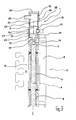
Figur 1- eine perspektivische auseinandergezogene Prinzipdarstellung eines erfindungsgemäßen Kabelkanalübergangs;
Figur 2- eine Außenansicht des in
Figur 1 gezeigten Kabelkanalübergangs im montierten Zustand; und Figur 3- eine Schnittdarstellung des in den
Figuren 1 und 2 gezeigten erfindungsgemäßen Kabelkanalübergangs.
- Figure 1
- a perspective exploded schematic diagram of a cable duct transition according to the invention;
- Figure 2
- an external view of the cable duct transition shown in Figure 1 in the assembled state; and
- Figure 3
- a sectional view of the cable duct transition according to the invention shown in Figures 1 and 2.
Ein im folgenden anhand der Figuren 1 bis 3 näher beschriebener
erfindungsgemäßer Kabelkanalübergang 1 bildet im gezeigten
Ausführungsbeispiel eine technisch-konstruktive Einheit
mit einer Türbandschwenklagerung 2, mittels der ein in den
Figuren 1 bis 3 nicht gezeigter Türflügel an einer in den Figuren
1 bis 3 ebenfalls nicht gezeigten Türzarge um eine in
Figur 3 durch eine Strichpunktlinie gekennzeichnete Schwenkachse
3 schwenkbar gelagert ist.One described in more detail below with reference to FIGS. 1 to 3
Zu der Türbandschwenklagerung gehört ein die Schwenkachse 3
ausbildender Schwenkzapfen 4, um den herum eine Scharnierhülse
5 eines türzargenseitigen Türbandes 6 und eine obere
Scharnierhülse 7 sowie eine untere Scharnierhülse 8 eines
türflügelseitigen Türbandes 9 koaxial und zueinander drehbar
gelagert sind.The
Bei dem in den Figuren 1 bis 3 gezeigten Ausführungsbeispiel
des Kabelkanalübergangs 1 ist dieser am oberen Ende der Türbandschwenklagerung
2 vorgesehen und er weist ein oberes,
türzargenfestes erstes Kabelkanalübergangsteil 10 und ein unteres,
türflügelfestes zweites Kabelkanalübergangsteil 11
auf.In the embodiment shown in Figures 1 to 3
of the
Zwischen dem unteren, türflügelfesten zweiten Kabelkanalübergangsteil
11 und dem oberen Ende des die Schwenkachse 3 der
Türbandschwenklagerung 2 ausbildenden Schwenkzapfens 4 ist im
gezeigten Ausführungsbeispiel ein Stiftkopf 12 angeordnet,
der mit einem Stiftabschnitt 13 in einer im oberen Endabschnitt
des Schwenkzapfens 4 mittig ausgebildeten Ausnehmung
14 sitzt.Between the lower, door leaf-fixed second cable
Ein Kopfabschnitt 15 des Stiftkopfes 12 sitzt auf der oberen
Stirnfläche des Schwenkzapfens 4 und ragt in Axialrichtung
über die obere Scharnierhülse 7 des türflügelseitigen Türbands
9 vor.A
Das untere, türflügelfeste zweite Kabelkanalübergangsteil 11
hat eine Kabelführungshülse 16, die koaxial zum Schwenkzapfen
4 der Türbandschwenklagerung 2 angeordnet ist und mit ihrer
unteren Stirnfläche gegen die obere Stirnfläche der oberen
Scharnierhülse 7 des türflügelseitigen Türbands 9 anliegt und
mit ihrem unteren Endabschnitt, dessen Innendurchmesser dem
Außendurchmesser des Kopfabschnitts 15 des Stiftkopfs 12 entspricht,
um den Kopfabschnitt 15 des Stiftkopfs 12 herum angeordnet
ist. Die untere Kabelführungshülse 16 hat einen radial
bzw. senkrecht zur Schwenkachse 3 der Türbandschwenklagerung
2 angeordneten Kabeleingangsstutzen 17, durch den ein
Kabel, welches elektrischen Einrichtungen im Bereich des in
den Figuren nicht dargestellten Türflügels zugeordnet ist,
vom Türflügel in die Kabelführungshülse 16 des unteren, türflügelfesten
zweiten Kabelkanalübergangsteils 11 hinein- bzw.
überführbar ist.The lower, door leaf-fixed second cable
Die untere Kabelführungshülse 16 hat im Bereich ihres oberen
Endabschnitts eine auf ihrer Innenumfangsfläche ausgebildete
innere Radialstufe 18.The lower
Oberhalb der unteren Kabelführungshülse 16 ist koaxial zu
dieser und zur Schwenkachse 3 der Türbandschwenklagerung 2
eine Kabelführungshülse 19 des oberen, türzargenfesten ersten
Kabelkanalübergangsteils 10 angeordnet. Diese obere Kabelführungshülse
19 ist im Bereich ihres oberen Endabschnitts mit
einem radial bzw. senkrecht zur Schwenkachse 3 der Türbandschwenklagerung
2 verlaufenden Kabeleingangsstutzen 20 versehen.
Mittels dieses Kabeleingangsstutzens 20 des oberen, türzargenfesten
ersten Kabelkanalübergangsteils 10 ist das vorstehend
bereits erwähnte Kabel von der in den Figuren nicht
gezeigten Türzarge her, im Bereich derselben es einer elektrischen
Einrichtung zugeordnet ist, in die obere Kabelführungshülse
19 einführbar.Above the lower
Die obere Kabelführungshülse 19 ist im Bereich ihres unteren
Endabschnitts auf ihrer Außenumfangsfläche mit einer äußeren
Radialstufe 21 ausgebildet. The upper
Die Abmessungen der inneren Radialstufe 18 der unteren Kabelführungshülse
16 und der äußeren Radialstufe 21 der oberen
Kabelführungshülse 19 sind so gewählt, daß der untere Endabschnitt
der oberen Kabelführungshülse 19 mit seiner Außenumfangsfläche
gegen die Innenumfangsfläche des oberen Endabschnitts
der unteren Kabelführungshülse 16 anliegt. Die obere
Kabelführungshülse 19 und die untere Kabelführungshülse 16
sind zueinander um die Schwenkachse 3 der Türbandschwenklagerung
2 verdrehbar.The dimensions of the inner
Beim Öffnen des in den Figuren nicht dargestellten Türflügels
erfolgt eine Relativverdrehung zwischen der unteren Kabelführungshülse
16 und der oberen Kabelführungshülse 19. Diese Relativverdrehung
entspricht maximal demjenigen Winkel, um den
der Türflügel in bezug auf die Türzarge mittels der Türbandschwenklagerung
2 schwenkbar gelagert ist. Das Kabel, das im
Kabelkanalübergang 1 zwischen Türflügel und Türzarge durch
den Kabeleingangsstutzen 17 des unteren, türflügelfesten
zweiten Kabelkanalübergangsteils 11, durch die untere Kabelführungshülse
16 desselben, die obere Kabelführungshülse 19
des oberen, türzargenfesten ersten Kabelkanalübergangsteils
10 und dessen Kabeleingangsstutzen 20 geführt ist, wird beim
Öffnen des Türflügels einer Torsions- bzw. Verdrillbeanspruchung
unterzogen, die sich aus dem Öffnungswinkel des Türflügels
in bezug auf die Türzarge ergibt und entsprechend durch
den maximal möglichen Öffnungswinkel des Türflügels in bezug
auf die Türzarge begrenzt ist.When opening the door wing, not shown in the figures
there is a relative rotation between the lower
Der durch das Kabelkanalübergangsteil 1 gebildete, der Überführung
des in den Figuren nicht dargestellten Kabels zwischen
Türzarge und Türflügel dienende Hohlraum wird gegen das
Eindringen von Fremdkörpern, Feuchtigkeit etc. geschützt, und
zwar durch einen ersten O-Dichtungsring 22, der zwischen der
Innenumfangsfläche des oberen Endabschnitts der unteren Kabelführungshülse
16 und der Außenumfangsfläche des Endabschnitts
der unteren Kabelführungshülse 19 angeordnet ist,
einen zweiten O-Dichtungsring 23, der zwischen der Außenumfangsfläche
des Kopfabschnitts 15 des Stiftkopfes 12 und der
Innenumfangsfläche des unteren Endabschnitts der unteren Kabelführungshülse
16 angeordnet ist, sowie durch eine Abdeckkappe
24, durch die das obere Ende der oberen Kabelführungshülse
19 geschlossen ist.The one formed by the cable
Auf der Außenumfangsfläche des oberen Abschnitts des Kabelkanalübergangs
1 ist eine obere Abdeckhülse 25 vorgesehen, die
sich von der Abdeckkappe 24 bzw. dem oberen Ende der oberen
Kabelführungshülse 19 des oberen, türzargenfesten ersten Kabelkanalübergangsteils
10 über die obere Kabelführungshülse
19 und die untere Kabelführungshülse 16 bis zum oberen Ende
des Kabeleingangsstutzens 17 des unteren, türflügelfesten
zweiten Kabelkanalübergangsteils 11 erstreckt. Die obere Abdeckhülse
25 ist mit einem Längsschlitz 26 ausgebildet, der
dem Kabeleingangsstutzen 20 des oberen, türzargenfesten ersten
Kabelkanalübergangsteils 10 zugeordnet ist.On the outer peripheral surface of the upper section of the
Mit ihrer unteren Stirnseite liegt die vorstehend geschilderte
obere Abdeckhülse 25 gegen eine obere Stirnseite einer unteren
Abdeckhülse 27 des Kabelkanalübergangs 1 an. Diese untere
Abdeckhülse 27 erstreckt sich von dem Bereich des oberen
Endes des Kabeleingangsstutzens 17 des unteren, türflügelfesten
zweiten Kabelkanalübergangsteils 11 bis zum unteren Ende
der unteren Kabelführungshülse 16 des unteren, türflügelfesten
zweiten Kabelkanalübergangsteils 11. Diese untere Abdeckhülse
27 hat einen Längsschlitz 28, der dem Kabeleingangsstutzen
17 des unteren, türflügelfesten zweiten Kabelkanalübergangsteils
11 zugeordnet ist.With its lower end face is the one described above
Mittels der oberen Abdeckhülse 25 und der unteren Abdeckhülse
27 des Kabelkanalübergangs 1 wird eine Ausgestaltung desselben
erreicht, bei der dessen Außenumfangsfläche mit der Außenumfangsfläche
der Scharnierhülsen 5, 7, 8 der Türbandschwenklagerung
2 fluchtet. Durch den vorstehend geschilderten
Kabelkanalübergang 1 ist eine unsichtbare Überleitung eines
Kabels zwischen einer Türzarge und einem Türflügel möglich.
Durch die angepaßte Ausgestaltung des Kabelkanalübergangs
1 an die Türbandschwenklagerung 2 wird erreicht, daß
überhaupt keine Hinweise auf die Existenz eines zwischen der
Türzarge und dem Türflügel verlaufenden Kabels sichtbar sind.By means of the
Claims (16)
Applications Claiming Priority (2)
| Application Number | Priority Date | Filing Date | Title |
|---|---|---|---|
| DE10153709 | 2001-10-31 | ||
| DE2001153709 DE10153709B4 (en) | 2001-10-31 | 2001-10-31 | Cable duct transition between a door leaf and a door frame |
Publications (2)
| Publication Number | Publication Date |
|---|---|
| EP1308593A2 true EP1308593A2 (en) | 2003-05-07 |
| EP1308593A3 EP1308593A3 (en) | 2005-08-17 |
Family
ID=7704316
Family Applications (1)
| Application Number | Title | Priority Date | Filing Date |
|---|---|---|---|
| EP02019685A Withdrawn EP1308593A3 (en) | 2001-10-31 | 2002-09-04 | Junction of a wire channel between a door wing and a door frame |
Country Status (2)
| Country | Link |
|---|---|
| EP (1) | EP1308593A3 (en) |
| DE (1) | DE10153709B4 (en) |
Cited By (3)
| Publication number | Priority date | Publication date | Assignee | Title |
|---|---|---|---|---|
| DE202006016439U1 (en) * | 2006-10-26 | 2008-03-06 | Dr. Hahn Gmbh & Co. Kg | Device for connecting cables |
| DE202010008551U1 (en) | 2010-09-16 | 2011-12-20 | Dr. Hahn Gmbh & Co. Kg | Arrangement for cable management |
| CN108075416A (en) * | 2017-12-19 | 2018-05-25 | 上海电信工程有限公司 | The cable management structure of substation's rotary wardrobe and lineation method |
Families Citing this family (1)
| Publication number | Priority date | Publication date | Assignee | Title |
|---|---|---|---|---|
| DE102005049487B4 (en) * | 2005-03-02 | 2010-05-20 | Huga Hubert Gaisendrees Gmbh & Co. Kg | Wooden door with light element |
Citations (3)
| Publication number | Priority date | Publication date | Assignee | Title |
|---|---|---|---|---|
| GB1182185A (en) * | 1967-05-23 | 1970-02-25 | F & C Gould Ltd | Improvements in and relating to Hinges. |
| DE9200361U1 (en) * | 1992-01-15 | 1992-03-05 | Schlaffner, Sabine, 8000 München | Hinge for bridging electrical cables on furniture etc. |
| DE19744423A1 (en) * | 1996-10-09 | 1998-04-16 | Hermann Loewe | Air-conditioning device for room |
Family Cites Families (2)
| Publication number | Priority date | Publication date | Assignee | Title |
|---|---|---|---|---|
| DE9309749U1 (en) * | 1993-06-30 | 1993-08-26 | Shen, Jack, Taipeh/T'ai-pei | Swivel joint for electrical devices |
| DE29601862U1 (en) * | 1996-02-05 | 1996-05-02 | Peters Design GmbH, 31737 Rinteln | Metal swivel with cable outlet |
-
2001
- 2001-10-31 DE DE2001153709 patent/DE10153709B4/en not_active Expired - Fee Related
-
2002
- 2002-09-04 EP EP02019685A patent/EP1308593A3/en not_active Withdrawn
Patent Citations (3)
| Publication number | Priority date | Publication date | Assignee | Title |
|---|---|---|---|---|
| GB1182185A (en) * | 1967-05-23 | 1970-02-25 | F & C Gould Ltd | Improvements in and relating to Hinges. |
| DE9200361U1 (en) * | 1992-01-15 | 1992-03-05 | Schlaffner, Sabine, 8000 München | Hinge for bridging electrical cables on furniture etc. |
| DE19744423A1 (en) * | 1996-10-09 | 1998-04-16 | Hermann Loewe | Air-conditioning device for room |
Cited By (5)
| Publication number | Priority date | Publication date | Assignee | Title |
|---|---|---|---|---|
| DE202006016439U1 (en) * | 2006-10-26 | 2008-03-06 | Dr. Hahn Gmbh & Co. Kg | Device for connecting cables |
| DE202010008551U1 (en) | 2010-09-16 | 2011-12-20 | Dr. Hahn Gmbh & Co. Kg | Arrangement for cable management |
| WO2012034970A1 (en) | 2010-09-16 | 2012-03-22 | Dr. Hahn Gmbh & Co. Kg | Arrangement for cable guiding |
| CN108075416A (en) * | 2017-12-19 | 2018-05-25 | 上海电信工程有限公司 | The cable management structure of substation's rotary wardrobe and lineation method |
| CN108075416B (en) * | 2017-12-19 | 2024-02-23 | 上海电信工程有限公司 | Cable arranging structure and cable arranging method for rotary cabinet of transformer substation |
Also Published As
| Publication number | Publication date |
|---|---|
| DE10153709B4 (en) | 2004-08-12 |
| EP1308593A3 (en) | 2005-08-17 |
| DE10153709A1 (en) | 2003-05-22 |
Similar Documents
| Publication | Publication Date | Title |
|---|---|---|
| DE3316834C3 (en) | Actuating mandrel for storage in a lock housing for a door lock for a control cabinet | |
| DE69702628T2 (en) | A hinge for metallic doors and windows | |
| EP1947279B2 (en) | End plug for the case of an actuating drive and device for fitting the case on a wing | |
| EP1489255B1 (en) | Door hinge for hidden assembly between door frame and door wing with a wire channel | |
| DE10153709B4 (en) | Cable duct transition between a door leaf and a door frame | |
| EP3333345B1 (en) | Hinge and door assembly | |
| EP2649258A1 (en) | Cable routing arrangement | |
| DE102019128325B3 (en) | hinge | |
| EP3867474B1 (en) | Hinge and method for mounting or de-mounting the hinge | |
| DE102005012704B4 (en) | Mixing faucet | |
| DE3228933A1 (en) | SWIVEL BEARINGS FOR DOORS, ESPECIALLY FOR PENDULAR DOORS | |
| EP3406839A1 (en) | Roller shutter unit with simplified motor change | |
| DE10353944A1 (en) | Damping device for toilet seats or toilet lids | |
| WO2022194950A1 (en) | Hinge for a door or a window | |
| EP1757762B2 (en) | Hinge joint, in particular for windows, doors or the like | |
| EP3885517A1 (en) | Cable guide for arrangement between a frame and a door | |
| DE9002696U1 (en) | hinge | |
| DE10329519B4 (en) | Door fitting with fall protection | |
| DE202009001856U1 (en) | Lock set for doors, windows or the like | |
| DE29603589U1 (en) | Hinge | |
| DE19728990C2 (en) | Cable holder for attaching and routing cables | |
| EP1134344A2 (en) | Articulation pin for doors, windows, flaps or similar | |
| DE10201563B4 (en) | Handle for a sanitary valve | |
| DE20000904U1 (en) | hinge | |
| DE8010810U1 (en) | Housing for electrical distribution and switchgear systems |
Legal Events
| Date | Code | Title | Description |
|---|---|---|---|
| PUAI | Public reference made under article 153(3) epc to a published international application that has entered the european phase |
Free format text: ORIGINAL CODE: 0009012 |
|
| AK | Designated contracting states |
Designated state(s): AT BE BG CH CY CZ DE DK EE ES FI FR GB GR IE IT LI LU MC NL PT SE SK TR |
|
| AX | Request for extension of the european patent |
Extension state: AL LT LV MK RO SI |
|
| PUAL | Search report despatched |
Free format text: ORIGINAL CODE: 0009013 |
|
| AK | Designated contracting states |
Kind code of ref document: A3 Designated state(s): AT BE BG CH CY CZ DE DK EE ES FI FR GB GR IE IT LI LU MC NL PT SE SK TR |
|
| AX | Request for extension of the european patent |
Extension state: AL LT LV MK RO SI |
|
| AKX | Designation fees paid | ||
| STAA | Information on the status of an ep patent application or granted ep patent |
Free format text: STATUS: THE APPLICATION IS DEEMED TO BE WITHDRAWN |
|
| 18D | Application deemed to be withdrawn |
Effective date: 20060221 |
|
| REG | Reference to a national code |
Ref country code: DE Ref legal event code: 8566 |