EP1308590B2 - Kantriegel für eine Tür - Google Patents
Kantriegel für eine Tür Download PDFInfo
- Publication number
- EP1308590B2 EP1308590B2 EP02405939A EP02405939A EP1308590B2 EP 1308590 B2 EP1308590 B2 EP 1308590B2 EP 02405939 A EP02405939 A EP 02405939A EP 02405939 A EP02405939 A EP 02405939A EP 1308590 B2 EP1308590 B2 EP 1308590B2
- Authority
- EP
- European Patent Office
- Prior art keywords
- door
- drop
- profiled
- locking bar
- down seal
- Prior art date
- Legal status (The legal status is an assumption and is not a legal conclusion. Google has not performed a legal analysis and makes no representation as to the accuracy of the status listed.)
- Expired - Lifetime
Links
- 238000007789 sealing Methods 0.000 claims abstract description 19
- 230000001419 dependent effect Effects 0.000 description 1
- 238000009413 insulation Methods 0.000 description 1
- 239000000463 material Substances 0.000 description 1
- 239000002184 metal Substances 0.000 description 1
- 239000003380 propellant Substances 0.000 description 1
- 230000000284 resting effect Effects 0.000 description 1
Images

Classifications
-
- E—FIXED CONSTRUCTIONS
- E05—LOCKS; KEYS; WINDOW OR DOOR FITTINGS; SAFES
- E05C—BOLTS OR FASTENING DEVICES FOR WINGS, SPECIALLY FOR DOORS OR WINDOWS
- E05C1/00—Fastening devices with bolts moving rectilinearly
- E05C1/02—Fastening devices with bolts moving rectilinearly without latching action
- E05C1/06—Fastening devices with bolts moving rectilinearly without latching action with operating handle or equivalent member moving otherwise than rigidly with the bolt
-
- E—FIXED CONSTRUCTIONS
- E05—LOCKS; KEYS; WINDOW OR DOOR FITTINGS; SAFES
- E05B—LOCKS; ACCESSORIES THEREFOR; HANDCUFFS
- E05B63/00—Locks or fastenings with special structural characteristics
- E05B63/06—Locks or fastenings with special structural characteristics with lengthwise-adjustable bolts ; with adjustable backset, i.e. distance from door edge
-
- E—FIXED CONSTRUCTIONS
- E05—LOCKS; KEYS; WINDOW OR DOOR FITTINGS; SAFES
- E05C—BOLTS OR FASTENING DEVICES FOR WINGS, SPECIALLY FOR DOORS OR WINDOWS
- E05C1/00—Fastening devices with bolts moving rectilinearly
- E05C1/02—Fastening devices with bolts moving rectilinearly without latching action
- E05C1/06—Fastening devices with bolts moving rectilinearly without latching action with operating handle or equivalent member moving otherwise than rigidly with the bolt
- E05C1/065—Fastening devices with bolts moving rectilinearly without latching action with operating handle or equivalent member moving otherwise than rigidly with the bolt flush
-
- E—FIXED CONSTRUCTIONS
- E06—DOORS, WINDOWS, SHUTTERS, OR ROLLER BLINDS IN GENERAL; LADDERS
- E06B—FIXED OR MOVABLE CLOSURES FOR OPENINGS IN BUILDINGS, VEHICLES, FENCES OR LIKE ENCLOSURES IN GENERAL, e.g. DOORS, WINDOWS, BLINDS, GATES
- E06B7/00—Special arrangements or measures in connection with doors or windows
- E06B7/16—Sealing arrangements on wings or parts co-operating with the wings
- E06B7/18—Sealing arrangements on wings or parts co-operating with the wings by means of movable edgings, e.g. draught sealings additionally used for bolting, e.g. by spring force or with operating lever
- E06B7/20—Sealing arrangements on wings or parts co-operating with the wings by means of movable edgings, e.g. draught sealings additionally used for bolting, e.g. by spring force or with operating lever automatically withdrawn when the wing is opened, e.g. by means of magnetic attraction, a pin or an inclined surface, especially for sills
-
- E—FIXED CONSTRUCTIONS
- E05—LOCKS; KEYS; WINDOW OR DOOR FITTINGS; SAFES
- E05C—BOLTS OR FASTENING DEVICES FOR WINGS, SPECIALLY FOR DOORS OR WINDOWS
- E05C7/00—Fastening devices specially adapted for two wings
- E05C7/04—Fastening devices specially adapted for two wings for wings which abut when closed
- E05C7/045—Sliding bolts mounted on or in the edge of a normally closed wing of a double-door or -window
Definitions
- the invention relates to a sealing and locking system for a threshold-free door according to the preamble of claim 1.
- lowerable door seals for threshold-free multi-leaf doors are known, which are arranged in the bottom region of the door and extend substantially over the entire width of the door. They serve as cold protection, as protection against drafts and as sound insulation.
- a lowering seal is for example off DE 195 16 530 and DE 200 02 108 known.
- US 5/857/291 discloses a fixing bolt for the passive leaf of a double door. Again, the brush seals of the two leaves ends spaced from the bolt.
- a lowering seal is described which is lowered by means of a locking bar actuated when locking the door.
- a bolt of the locking rod passes through the lowering seal.
- the locking bolt of the channel bolt is arranged in the horizontal direction to the door surface offset from the actuating rod.
- it has a stroke, which is measured below the lower edge of its mounting rail greater than the sum of the stroke of Absenkdichtung and the height of Absenkdichtung. This makes it possible, on the one hand, to make the locking bolt adjustable in height.
- the channel bar with its lower edge of the housing rail can be mounted resting on the lowering seal.
- the lowering seal can be fixed at an angle of the channel bolt without having to pay attention to the dimensional stability during production and when installing the door.
- the lowering seal can be simplified and installed quickly due to the angle.
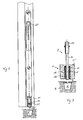
- FIGS. 1 to 3 a canotage is shown in a sealing and locking system according to the invention.
- a Kantriegel 2 In a longitudinal groove 4 in the vertical end face of a door T a Kantriegel 2 is fixed. It has a U-shaped mounting rail 20 which is preferably aligned with its web with the vertical end face of the door T. The web is penetrated by an actuating lever 21, which is either slidable or foldable in an upper and a lower position. On the actuating lever 21, an actuating rod 22 is arranged, which extends within the mounting rail 20 and by means of the lever 21 in the vertical direction can be raised and lowered. It is shown in dashed lines in the drawing. The actuating rod 22 is cranked at its lower end.
- a lowering seal 1 of known type.
- the lowering seal 1 is preferably as in DE 195 16 530 described designed. However, it can also be used other Absenkdichtungen this.
- the lowering seal 1 essentially comprises a U-shaped housing rail 10 and a lowering element arranged therein and can be raised and lowered by a spring-loaded lowering mechanism, not shown.
- the housing rail 10 is aligned with the lower end face of the door T, as shown here.
- the lowering element consists in the example shown here of a lowering rail 12 made of metal and an attached elastic sealing profile element 13.
- a sealing mat 11 is arranged, which rests on the Absenkelement or is absorbed by this. All these elements of Absenkdichtung 1 have through holes 10 ', 11', 12 ', 13', which are aligned with each other in a vertical line. The passage openings 10 ', 11', 12 ', 13' are completely closed and have no on or cutouts. Furthermore, a sliding guide element 14 is arranged in the upper region, which has a slightly smaller passage opening than the other elements. This sliding guide element 14 is made of a good sliding material, in particular of a plastic.
- the locking bolt 24 passes through the passage openings 10 ', 11', 12 ', 13' of the lowering seal 1. In this case, it is preferably at least sealed by the sealing profile element 13. Preferably, he already enforced it in the raised state. However, it is also possible that he ends up higher in this state. It is essential, however, that it protrudes in its lowered state a lower edge 20 'of the mounting rail 20 by a distance which is greater than the sum of the distance of raising and lowering the Absenkdichtung 1 plus the height of Absenkdichtung 1 itself. This ensures that the locking bolt 24 can actually be used for locking by, as in FIGS. 1 to 4 is shown, the passage openings penetrated and engages with its lower end in a locking recess 5 in the bottom B below the door T.
- the locking bolt 24 is flattened in its lower, in the lowered state below the lower edge 20 'of the mounting rail 20 projecting part 25.
- this part has a rectangular cross-section. However, it can also be round, oval or with another cross-section.
- the lowering seal 1 is arranged in the mounted state below the channel bolt 2, wherein they, as in FIG. 1 is shown, preferably in the front end region with this aligned, so that it seals the entire width of the door.
- the mounting rail 20 is provided below its lower edge with a mounting bracket 26.
- the web of the rail for this purpose has a free extended end, which is bent backwards to the door surface.
- This mounting bracket 26 engages under the housing rail 10 of the lowering seal 1, so that this is held at one of its ends by the channel latch 2. Only the other, hinged end must therefore be attached directly to the door.
- the device according to the invention thus enables optimum sealing of a door slot even when using a channel latch.
- the channel latch allows easy and quick attachment of Absenkdichtung.
- the locking bolt is arranged so that it can be easily adapted in its stroke.
Landscapes
- Engineering & Computer Science (AREA)
- Structural Engineering (AREA)
- Mechanical Engineering (AREA)
- Civil Engineering (AREA)
- Specific Sealing Or Ventilating Devices For Doors And Windows (AREA)
- Securing Of Glass Panes Or The Like (AREA)
- Connection Of Plates (AREA)
- Vehicle Step Arrangements And Article Storage (AREA)
- Power-Operated Mechanisms For Wings (AREA)
- Hinges (AREA)
Description
- Die Erfindung betrifft ein Dichtungs- und Verriegelungssystem für eine schwellenlose Tür gemäss Oberbegriff des Patentanspruches 1.
- Aus dem Stand der Technik sind Türen mit handbetätigbaren Kantriegeln bekannt. Üblicherweise weisen sie eine Befestigungs-Profilschiene auf, welche an oder in der Stirnfläche der Türe befestigbar ist. In der Befestigungs-Profilschiene ist ein Betätigungshebel angeordnet, welcher mit einer Betätigungsstange verbunden ist. An ihrem unteren Ende geht die Betätigungsstange in einen Riegelbolzen über, welcher mittels des Betätigungshebels absenkbar und anhebbar ist und im abgesenkten Zustand in eine Verriegelungsmulde im Boden hineinragt, so dass die Türe verriegelt ist.
DE 198 32 356 offenbart ein Beispiel eines Kantriegelbeschlags. - Des weiteren sind im Stand der Technik absenkbare Türdichtungen für schwellenlose Mehrflügeltüren bekannt, welche im Bodenbereich der Türe angeordnet sind und sich im wesentlichen über die gesamte Breite der Türe erstrecken. Sie dienen als Kälteschutz, als Schutz vor Zugluft und als Schallschutz. Eine derartige Absenkdichtung ist beispielsweise aus
DE 195 16 530 undDE 200 02 108 bekannt. - Bei Türen, welche sowohl mit einem Kantriegel wie auch mit einer Absenkdichtung versehen sind, wird dies so gelöst, dass sich die Absenkdichtung nicht über die gesamte Breite der Türe erstreckt, sondern um das vom Kantriegel benötige Mass zurückversetzt endet. Dies weist jedoch den Nachteil auf, dass die Türe nicht vollständig gedichtet ist, sondern vorne ein ungedichteter Bereich bestehen bleibt.
-
US 5/857/291 offenbart einen Fixierungsbolzen für den Standflügel einer Doppeltüre. Auch hier enden die Bürstendichtungen der zwei Türflügel beabstandet zum Bolzen. - Ferner offenbart
US-A-3/940/886 einen Treibriegel für eine Tür mit einem Verriegelungsbolzen, welcher über ein Gestänge mit einer Betätigungsstange verbunden ist, wobei das Gestänge parallel versetzt zur Betätigungsstange verläuft. - In
DD-A-291 117 - In der nachveröffentlichten
EP-A-1/191/182 wird ein Treibriegel offenbart, welcher eine Absenkdichtung durchsetzt. - Ausgehend von diesem Stand der Technik ist es deshalb Aufgabe der Erfindung, ein Dichtungs- und Verschlusssystem zu schaffen, welches eine kostengünstige, optimal dichtende Kombination von einem Kantriegel mit einer Absenkdichtung ermöglicht.
- Diese Aufgabe löst ein Dichtungs- und Verschlusssystem mit den Merkmalen des Patentanspruches 1.
- Es ist eine weitere Aufgabe der Erfindung, ein Dichtungs- und Verschlusssystem zu ermöglichen, welches sich für schmale Türen mit einer möglichst dünnen Absenkdichtung einsetzen lässt.
- Diese Aufgabe löst ein Dichtungs- und Verschlusssystem mit den Merkmalen des Patentanspruches 6.
- Beim erfindungsgemässen Dichtungs- und Verschlusssystem ist der Riegelbolzendes Kantriegels in horizontaler Richtung zur Türfläche hin versetzt zur Betätigungsstange angeordnet. Zudem weist er einen Hubweg auf, welcher unterhalb der unteren Kante seiner Befestigungs-Profilschiene gemessen grösser ist als die Summe des Hubweges der Absenkdichtung und der Höhe der Absenkdichtung. Dadurch ist es einerseits möglich, den Riegelbolzen höhenverstellbar zu gestalten. Des weiteren lässt sich der Kantriegel mit seiner unteren Kante der Gehäuse-Profilschiene auf der Absenkdichtung aufliegend befestigen. Dabei lässt sich die Absenkdichtung an einem Winkel des Kantriegels befestigen, ohne dass auf Masshaltung bei der Produktion und beim Einbau der Türe geachtet werden muss. Die Absenkdichtung lässt sich aufgrund des Winkels vereinfacht und schnell montieren.
- Durch die Abflachung des der unteren Kante vorstehenden Teils des Riegelbolzens ist es möglich, diesen relativ dünn und trotzdem stabil zu gestalten, so dass sich auch relativ dünne Absenkdichtungen noch von Riegelbolzen durchsetzen lassen.
- Weitere vorteilhafte Ausführungsformen gehen aus den abhängigen Patentansprüchen hervor.
- Im folgenden wird der Erfindungsgegenstand anhand eines bevorzugten Ausführungsbeispieles, welches in der beiliegenden Zeichnung dargestellt ist, erläutert. Es zeigen:
- Figur 1
- eine teilweise geschnittene Seitenansicht auf eine Stirnfläche einer Tür in ihrem unteren Bereich;
- Figur 2
- eine Ansicht auf die Türe von vorne;
- Figur 3
- einen Schnitt durch eine Türfläche in ihrem unteren Bereich und
- Figur 4
- eine Draufsicht auf eine vom Kantriegel durchstossene Absenkdichtung.
- In den
Figuren 1 bis 3 ist ein Kantriegel in einem Dichtungs-und Verriegelungssystem gemäss der Erfindung dargestellt. - In einer Längsnut 4 in der vertikalen Stirnfläche einer Türe T ist ein Kantriegel 2 befestigt. Er weist eine u-förmige Befestigungs-Profilschiene 20 auf, welche mit ihrem Steg vorzugsweise mit der vertikalen Stirnfläche der Türe T fluchtet. Der Steg wird von einem Betätigungshebel 21 durchsetzt, welcher entweder schiebbar oder in eine obere und eine untere Position klappbar ist. Am Betätigungshebel 21 ist eine Betätigungsstange 22 angeordnet, welche innerhalb der Befestigungs-Profilschiene 20 verläuft und mittels des Hebels 21 in vertikaler Richtung anhebbar und absenkbar ist. Sie ist in der Zeichnung strichliniert dargestellt. Die Betätigungsstange 22 ist an ihrem unteren Ende gekröpft. Sie kann auch, wie hier dargestellt ist, als Winkelelement mit einem rechten Winkel ausgebildet sein, wobei ein horizontal verlaufender Schenkel 22' in die Türfläche hineinragt. An diesem Schenkel 22' ist ein Riegelbolzen 24 angeordnet. Hierbei ist er über ein Stellgewinde 23 bezüglich der Betätigungsstange 22 in vertikaler Richtung höhenverstellbar.
- In einer unteren horizontalen Stirnfläche der Türe T ist, wie ebenfalls in den
Figuren 1 bis 3 dargestellt ist, in einer horizontal verlaufenden Quernut 3 eine Absenkdichtung 1 bekannter Art angeordnet. Die Absenkdichtung 1 ist vorzugsweise wie inDE 195 16 530 beschrieben gestaltet. Es lassen sich jedoch auch andere Absenkdichtungen hierfür einsetzen. Die Absenkdichtung 1 umfasst im wesentlichen eine u-förmige Gehäuseschiene 10 und ein darin angeordnetes, mit einem nicht dargestellten federbelastete Absenkmechanismus anhebbaren und absenkbaren Absenkelement. Vorzugsweise fluchtet die Gehäuse-Profilschiene 10 mit der unteren Stirnfläche der Türe T, wie dies hier dargestellt ist. Das Absenkelement besteht im hier dargestellten Beispiel aus einer Absenk-Profilschiene 12 aus Metall und einem daran befestigten, elastischen Dichtungs-Profilelement 13. Vorzugsweise ist in der Absenkdichtung ferner noch eine Dichtungsmatte 11 angeordnet, welche auf dem Absenkelement aufliegt beziehungsweise von diesem aufgenommen ist. Alle diese Elemente der Absenkdichtung 1 weisen Durchgangsöffnungen 10', 11', 12', 13' auf, welche in einer vertikalen Linie miteinander fluchten. Die Durchgangsöffnungen 10', 11', 12', 13' sind vollständig geschlossen und weisen keinerlei An- oder Ausschnitte auf. Ferner ist im oberen Bereich ein Gleit-Führungselement 14 angeordnet, welches eine etwas kleinere Durchgangsöffnung aufweist als die übrigen Elemente. Dieses Gleit-Führungselement 14 ist aus einem gut gleitenden Material gefertigt, insbesondere aus einem Kunststoff. - Der Riegelbolzen 24 durchsetzt die Durchgangsöffnungen 10', 11', 12', 13' der Absenkdichtung 1. Dabei ist er vorzugsweise mindestens vom Dichtungs-Profilelement 13 dichtend umschlossen. Vorzugsweise durchsetzt er sie bereits im angehobenen Zustand. Es ist jedoch auch möglich, dass er in diesem Zustand höher als diese endet. Wesentlich ist jedoch, dass er in seinem abgesenkten Zustand einer unteren Kante 20' der Befestigungs-Profilschiene 20 um eine Distanz vorsteht, welche grösser ist als die Summe der Distanz der Anhebung und Absenkung der Absenkdichtung 1 plus der Höhe der Absenkdichtung 1 selber. Dadurch ist gewährleistet, dass der Riegelbolzen 24 sich tatsächlich zur Verriegelung einsetzen lässt, indem er, wie in
Figuren 1 bis 4 dargestellt ist, die Durchgangsöffnungen durchsetzt und mit seinem unteren Ende in eine Verriegelungsmulde 5 im Boden B unterhalb der Türe T eingreift. - Damit eine möglichst schmale Absenkdichtung 1 verwendet werden kann, ist der Riegelbolzen 24 in seinem unteren, im abgesenkten Zustand unterhalb der unteren Kante 20' der Befestigungs-Profilschiene 20 herausragenden Teil 25 abgeflacht ausgebildet. Vorzugsweise weist dieser Teil einen rechteckigen Querschnitt auf. Er lässt sich jedoch auch rund, oval oder mit einem anderen Querschnitt ausbilden.
- Die Absenkdichtung 1 ist im montierten Zustand unterhalb des Kantriegels 2 angeordnet, wobei sie, wie in
Figur 1 dargestellt ist, vorzugsweise im vorderen stirnseitigen Bereich mit dieser fluchtet, so dass sie die gesamte Breite der Türe abdichtet. - Die Befestigungs-Profilschiene 20 ist unterhalb ihrer unteren Kante mit einem Befestigungswinkel 26 versehen. Vorzugsweise weist der Steg der Schiene hierfür ein freies verlängertes Ende auf, welches nach hinten zur Türfläche gebogen ist. Dieser Befestigungswinkel 26 untergreift die Gehäuse-Profilschiene 10 der Absenkdichtung 1, so dass diese an einem ihrer Enden vom Kantriegel 2 gehalten ist. Nur das andere, scharnierseitige Ende muss somit noch direkt an der Türe befestigt werden.
- Die erfindungsgemässe Vorrichtung ermöglicht somit eine optimale Abdichtung eines Türschlitzes auch bei Verwendung eines Kantriegels. Zudem ermöglicht der Kantriegel eine einfache und schnelle Befestigung der Absenkdichtung. Des weiteren ist der Riegelbolzen so angeordnet, dass er auf einfache Art und Weise in seinem Hub angepasst werden kann.
-
- T
- Türflügel
- B
- Boden
- 1
- Absenkdichtung
- 10
- Gehäuse-Profilschiene
- 10'
- erste Durchlassöffnung
- 11
- Dichtungsmatte
- 11'
- zweite Durchlassöffnung
- 12
- Absenk-Profilschiene
- 12'
- dritte Durchlassöffnung
- 13
- Dichtungs-Profilelement
- 13'
- dritte Durchlassöffnung
- 14
- Führungselement
- 2
- Kantriegel
- 20
- Befestigungs-Profilschiene
- 20'
- untere Kante
- 21
- Betätigungshebel
- 22
- Betätigungsstange
- 22'
- Schenkel
- 23
- Stellgewinde
- 24
- Riegelbolzen
- 25
- Abgeflachter herausragender Teil
- 26
- Befestigungswinkel
- 3
- Quernut
- 4
- Längsnut
- 40
- Stufe
- 41
- Ausnehmung
- 5
- Verriegelungsmulde
Claims (10)
- Dichtungs- und Verriegelungssystem für eine schwellenlose Tür (T) mit einer Absenkdichtung (1) und einem Kantriegel (2), wobei der Kantriegel (2) eine in oder an einer Stirnfläche der Türe (T) befestigbare Befestigungs-Profilschiene (20), einen Betätigungshebel (21), welcher die Profilschiene durchsetzt, eine mittels des Betätigungshebels (21) anhebbare und absenkbare Betätigungsstange (22) und einen mit der Betätigungsstange (22) verbundenen Riegelbolzen (24) aufweist, wobei der Riegelbolzen (24) in seinem abgesenkten Zustand einer unteren Kante (20') der Befestigungs-Profilschiene (20) um eine Distanz vorsteht, welche grösser ist als ein Hub der Absenkdichtung (1) plus einer Höhe der Absenkdichtung (1) selber, und wobei die Absenkdichtung (1) im eingebauten Zustand in einer unteren horizontalen Stirnfläche der Tür angeordnet ist, dadurch gekennzeichnet, dass der Riegelbolzen (24) in horizontaler Richtung zu einer Fläche der Türe (T) hin versetzt zur Betätigungsstange (22) angeordnet ist und dass der Riegelbolzen (2) mindestens im abgesenkten Zustand die Absenkdichtung (1) durchsetzt.
- System nach Anspruch 1, wobei die Absenkdichtung (1) eine Gehäuse-Profilschiene (10) und ein darin verschiebbar gehaltenes, sich über die Breite der Türe (T) erstreckendes Dichtungs-Profilelement (13) aufweist, wobei in der Gehäuse-Profilschiene (10), im Dichtungs-Profilelement (13) und in allfälligen anderen Elementen (11, 12) der Absenkdichtung (1) je eine miteinander in vertikaler Richtung fluchtende Durchlassöffnung (10', 11', 12' , 13') vorhanden ist, welche vom Riegelbolzen (24) durchdringbar ist.
- System nach einem der Ansprüche 1 oder 2, wobei die Absenkdichtung ein Gleit-Führungselement (14) aufweist, durch welches der Riegelbolzen (24) des Kantriegels (2) geführt verschiebbar ist.
- System nach einem der Ansprüche 1 bis 3, wobei sich die Absenkdichtung (1) im eingebauten Zustand unterhalb der Befestigungs-Profilschiene (20) des Kantriegels (2) erstreckt und mit dieser im vorderen stirnseitigen Bereich der Tür annähernd fluchtet.
- System nach Anspruch 2, wobei die Absenkdichtung (1) am Kantriegel (2) befestigt ist, indem ein an der Befestigungs-Profilschiene (20) angeformtes winkelelement (26) die Gehäuse-Profilschiene (10) der Absenkdichtung (1) untergreift.
- System nach einem der Ansprüche 1 bis 5, wobei der Riegelbolzen (24) in seinem unteren, im abgesenkten Zustand unterhalb der unteren Kante (20') der Befestigungs-Profilschiene (20) herausragenden Teil (25) im Durchmesser verjüngt ist.
- System nach Anspruch 6, wobei der Riegelbolzen (24) in diesem unteren Teil (25) einen rechteckigen, runden oder ovalen Querschnitt aufweist.
- System nach Anspruch 1, wobei der Riegelbolzen (24) mittels eines Stellgewindes (23) bezüglich der Betätigungsstange (22) höhenverstellbar ist.
- System nach Anspruch 1, wobei die Betätigungsstange (22) als Winkelelement ausgebildet ist, wobei ein erster vertikal verlaufender Schenkel des Winkels mit dem Betätigungshebel (21) verbunden ist und an einem zweiten horizontal verlaufenden Schenkel (22') des Winkels der Riegelbolzen (24) angeordnet ist.
- System nach Anspruch 1, wobei die Befestigungs-Profilschiene (20) an ihrer unteren Kante (20') ein sich zur Türfläche hin erstreckendes Winkelelement (26) zur Befestigung der Absenkdichtung (1) aufweist.
Applications Claiming Priority (2)
| Application Number | Priority Date | Filing Date | Title |
|---|---|---|---|
| CH20332001 | 2001-11-06 | ||
| CH20332001 | 2001-11-06 |
Publications (3)
| Publication Number | Publication Date |
|---|---|
| EP1308590A1 EP1308590A1 (de) | 2003-05-07 |
| EP1308590B1 EP1308590B1 (de) | 2006-08-30 |
| EP1308590B2 true EP1308590B2 (de) | 2011-11-02 |
Family
ID=4567223
Family Applications (1)
| Application Number | Title | Priority Date | Filing Date |
|---|---|---|---|
| EP02405939A Expired - Lifetime EP1308590B2 (de) | 2001-11-06 | 2002-11-04 | Kantriegel für eine Tür |
Country Status (5)
| Country | Link |
|---|---|
| EP (1) | EP1308590B2 (de) |
| AT (1) | ATE338185T1 (de) |
| DE (2) | DE20221596U1 (de) |
| ES (1) | ES2269643T5 (de) |
| HK (1) | HK1052955B (de) |
Families Citing this family (11)
| Publication number | Priority date | Publication date | Assignee | Title |
|---|---|---|---|---|
| DE20221596U1 (de) † | 2001-11-06 | 2006-07-20 | Planet Gdz Ag | Kantriegel für eine Tür |
| ES2310105B1 (es) * | 2006-10-27 | 2009-10-26 | Juan Antonio Cabello Pedreño | Embellecedor para suelo/marco de pestillo/pasador de puertas. |
| PL2050918T3 (pl) | 2007-10-19 | 2016-04-29 | Planet Gdz Ag | Uszczelka opadająca wyposażona w otwór przelotowy |
| DE202009000326U1 (de) | 2009-01-08 | 2009-04-09 | F. Athmer Ohg | Tür mit Türflügel, Dichtung und Kantriegel und Anordnung aus Dichtung und Kantriegel |
| IT1392997B1 (it) * | 2009-02-03 | 2012-04-02 | Geron | Assieme di guarnizione per ante di serramenti nonche' metodo di assemblaggio di tale assieme |
| CH702814A1 (de) | 2010-03-02 | 2011-09-15 | Planet Gdz Ag | Verriegelungsmulde. |
| EP2876233A1 (de) | 2013-11-21 | 2015-05-27 | Planet GDZ AG | Kantriegel und Türdichtungssystem |
| US10233673B2 (en) | 2015-01-26 | 2019-03-19 | Schlage Lock Company Llc | Adjustable backset latch |
| EP3112577B1 (de) * | 2015-07-01 | 2017-08-30 | Planet GDZ AG | Absenkdichtung |
| DE202015009091U1 (de) | 2015-07-01 | 2016-09-09 | Planet Gdz Ag | Absenkdichtung |
| EP3543438A1 (de) * | 2018-03-22 | 2019-09-25 | dormakaba Deutschland GmbH | Schliessanordnung mit zumindest einer riegelstange |
Citations (11)
| Publication number | Priority date | Publication date | Assignee | Title |
|---|---|---|---|---|
| US761145A (en) † | 1904-01-28 | 1904-05-31 | Russell & Erwin Mfg Co | Flush-bolt. |
| US967377A (en) † | 1910-05-18 | 1910-08-16 | P & F Corbin | Flush bolt. |
| DE537981C (de) † | 1931-11-09 | Heinrich Strenger Fa | Kantenriegel mit einer in einem rechteckigen Gehaeuse gefuehrten, durch Schleiffeder gehaltenen Riegelstange | |
| DE854001C (de) † | 1951-07-03 | 1952-10-30 | Weidtmann Fa Wilhelm | Tuerkantriegel |
| AT173065B (de) † | 1949-09-21 | 1952-11-10 | Hans Max | Türkantriegel |
| DE867813C (de) † | 1949-09-21 | 1953-02-19 | Hans Max | Tuerkantenriegel |
| DE869610C (de) † | 1951-10-17 | 1953-03-05 | Erich Leicht Fa | Kantenriegel mit beiderseits umlegbarem Griffhebel |
| US2815975A (en) † | 1955-08-16 | 1957-12-10 | Yale & Towne Mfg Co | Flush bolt for a door |
| US5004277A (en) † | 1988-08-01 | 1991-04-02 | Triangle Brass Manufacturing Company | Flush bolt mechanism for double doors |
| JPH11117640A (ja) † | 1997-10-17 | 1999-04-27 | Mitsuboshi Belting Ltd | フランス落し器具付き旋回ドアのシール装置 |
| EP1308590A1 (de) † | 2001-11-06 | 2003-05-07 | Planet GDZ AG | Kantriegel für eine Tür |
Family Cites Families (9)
| Publication number | Priority date | Publication date | Assignee | Title |
|---|---|---|---|---|
| US3888046A (en) * | 1972-07-17 | 1975-06-10 | Kawneer Co | Automatic astragal |
| US3940886A (en) * | 1973-01-05 | 1976-03-02 | American Device Manufacturing Company | Panic exit door locking structure |
| US4052819A (en) * | 1977-01-17 | 1977-10-11 | Pease Company | Double door astragal |
| DD291117A5 (de) * | 1989-12-28 | 1991-06-20 | Veb Holz- Und Leichtmetallbauelemente,De | Untere abdichtung einer schwellenlosen tuer |
| DE29515591U1 (de) * | 1995-09-29 | 1995-12-14 | Hampel-Zöllner Gesellschaft für klassisches Fenster-Design mbH, 86504 Merching | Glasfasersperrstange |
| US5857291A (en) * | 1996-12-20 | 1999-01-12 | Headrick Manufacturing Company | Astragal with integral sealing lock block |
| DE19832356C2 (de) * | 1998-07-20 | 2001-09-27 | Aubi Baubeschlaege Gmbh | Kantenriegelbeschlag |
| DE20002108U1 (de) * | 2000-02-07 | 2000-04-20 | PLANET GDZ AG, Nürensdorf | Türflügel für eine schwellenlose Türe |
| ATE513112T1 (de) * | 2000-09-25 | 2011-07-15 | Planet Gdz Ag | Absenkdichtung für eine schwellenlose tür |
-
2002
- 2002-11-04 DE DE20221596U patent/DE20221596U1/de not_active Expired - Lifetime
- 2002-11-04 DE DE50207987T patent/DE50207987D1/de not_active Expired - Lifetime
- 2002-11-04 AT AT02405939T patent/ATE338185T1/de active
- 2002-11-04 ES ES02405939T patent/ES2269643T5/es not_active Expired - Lifetime
- 2002-11-04 EP EP02405939A patent/EP1308590B2/de not_active Expired - Lifetime
-
2003
- 2003-07-21 HK HK03105244.0A patent/HK1052955B/zh not_active IP Right Cessation
Patent Citations (11)
| Publication number | Priority date | Publication date | Assignee | Title |
|---|---|---|---|---|
| DE537981C (de) † | 1931-11-09 | Heinrich Strenger Fa | Kantenriegel mit einer in einem rechteckigen Gehaeuse gefuehrten, durch Schleiffeder gehaltenen Riegelstange | |
| US761145A (en) † | 1904-01-28 | 1904-05-31 | Russell & Erwin Mfg Co | Flush-bolt. |
| US967377A (en) † | 1910-05-18 | 1910-08-16 | P & F Corbin | Flush bolt. |
| AT173065B (de) † | 1949-09-21 | 1952-11-10 | Hans Max | Türkantriegel |
| DE867813C (de) † | 1949-09-21 | 1953-02-19 | Hans Max | Tuerkantenriegel |
| DE854001C (de) † | 1951-07-03 | 1952-10-30 | Weidtmann Fa Wilhelm | Tuerkantriegel |
| DE869610C (de) † | 1951-10-17 | 1953-03-05 | Erich Leicht Fa | Kantenriegel mit beiderseits umlegbarem Griffhebel |
| US2815975A (en) † | 1955-08-16 | 1957-12-10 | Yale & Towne Mfg Co | Flush bolt for a door |
| US5004277A (en) † | 1988-08-01 | 1991-04-02 | Triangle Brass Manufacturing Company | Flush bolt mechanism for double doors |
| JPH11117640A (ja) † | 1997-10-17 | 1999-04-27 | Mitsuboshi Belting Ltd | フランス落し器具付き旋回ドアのシール装置 |
| EP1308590A1 (de) † | 2001-11-06 | 2003-05-07 | Planet GDZ AG | Kantriegel für eine Tür |
Also Published As
| Publication number | Publication date |
|---|---|
| ES2269643T5 (es) | 2012-02-28 |
| ATE338185T1 (de) | 2006-09-15 |
| DE50207987D1 (de) | 2006-10-12 |
| EP1308590B1 (de) | 2006-08-30 |
| HK1052955B (zh) | 2007-01-19 |
| DE20221596U1 (de) | 2006-07-20 |
| ES2269643T3 (es) | 2007-04-01 |
| HK1052955A1 (zh) | 2003-10-03 |
| EP1308590A1 (de) | 2003-05-07 |
Similar Documents
| Publication | Publication Date | Title |
|---|---|---|
| EP3165703B1 (de) | Absenkbare dichtungsvorrichtung | |
| EP3452681B1 (de) | Dichtungsvorrichtung für eine schiebetür | |
| EP1308590B1 (de) | Kantriegel für eine Tür | |
| EP0294630B1 (de) | Verriegelungsbeschlag für Fenster, Türen od.dgl. | |
| EP3752700B1 (de) | Absenkbare einbruchsicherung | |
| EP3112577B1 (de) | Absenkdichtung | |
| EP3241974A1 (de) | Anordnung für eine dichtung, insbesondere für eine auflaufdichtung oder für eine sich selbsttätig absenkende bodendichtung für türen | |
| DE19521601C1 (de) | Fenster, Tür oder dergleichen | |
| EP2182159B1 (de) | Absenkbare Türdichtung | |
| EP2050918A2 (de) | Absenkdichtung mit Durchgangsöffnung | |
| EP1936086B1 (de) | Ecklagerbeschlag für Fenster, Türen oder dgl. | |
| DE69810009T2 (de) | Verriegelungsvorrichtung für einen Schiebeflügel | |
| EP3728778B1 (de) | Türflügel mit dichtungssystem | |
| DE3150029C2 (de) | Treibstangenverschluß mit Eckumlenkung für Fenster und Türen od.dgl. | |
| EP2099989B1 (de) | Treibstangengetriebe | |
| EP1447514B1 (de) | Absenkbare Türdichtung einer Schiebetür | |
| EP3543454A1 (de) | Rollladenkasten, sowie adapterleiste | |
| DE29513098U1 (de) | Fenster/Tür mit Dreh-Kipp-Beschlag | |
| EP1746235B1 (de) | Beschlaganordnung | |
| EP2132391B1 (de) | Treibstangenanordnung mit mindestens einer treibstange und mindestens einem treibstangenführungselement | |
| EP0730074B1 (de) | Kantriegelbeschlag für Standflügel von doppelflügeligen Türen | |
| EP1277910B1 (de) | Schwellenlose Türe mit absenkbarer Dichtung | |
| DE9411037U1 (de) | Sicherheitstür | |
| EP3085876B1 (de) | Absenkdichtungsvorrichtung | |
| DE9216213U1 (de) | Schließplatte |
Legal Events
| Date | Code | Title | Description |
|---|---|---|---|
| PUAI | Public reference made under article 153(3) epc to a published international application that has entered the european phase |
Free format text: ORIGINAL CODE: 0009012 |
|
| AK | Designated contracting states |
Designated state(s): AT BE BG CH CY CZ DE DK EE ES FI FR GB GR IE IT LI LU MC NL PT SE SK TR |
|
| AX | Request for extension of the european patent |
Extension state: AL LT LV MK RO SI |
|
| 17P | Request for examination filed |
Effective date: 20030531 |
|
| AKX | Designation fees paid |
Designated state(s): AT BE BG CH CY CZ DE DK EE ES FI FR GB GR IE IT LI LU MC NL PT SE SK TR |
|
| AXX | Extension fees paid |
Extension state: LT Payment date: 20030531 Extension state: SI Payment date: 20030531 Extension state: LV Payment date: 20030531 |
|
| 17Q | First examination report despatched |
Effective date: 20040510 |
|
| GRAP | Despatch of communication of intention to grant a patent |
Free format text: ORIGINAL CODE: EPIDOSNIGR1 |
|
| GRAS | Grant fee paid |
Free format text: ORIGINAL CODE: EPIDOSNIGR3 |
|
| GRAA | (expected) grant |
Free format text: ORIGINAL CODE: 0009210 |
|
| AK | Designated contracting states |
Kind code of ref document: B1 Designated state(s): AT BE BG CH CY CZ DE DK EE ES FI FR GB GR IE IT LI LU MC NL PT SE SK TR |
|
| AX | Request for extension of the european patent |
Extension state: LT LV SI |
|
| PG25 | Lapsed in a contracting state [announced via postgrant information from national office to epo] |
Ref country code: IT Free format text: LAPSE BECAUSE OF FAILURE TO SUBMIT A TRANSLATION OF THE DESCRIPTION OR TO PAY THE FEE WITHIN THE PRESCRIBED TIME-LIMIT;WARNING: LAPSES OF ITALIAN PATENTS WITH EFFECTIVE DATE BEFORE 2007 MAY HAVE OCCURRED AT ANY TIME BEFORE 2007. THE CORRECT EFFECTIVE DATE MAY BE DIFFERENT FROM THE ONE RECORDED. Effective date: 20060830 Ref country code: IE Free format text: LAPSE BECAUSE OF FAILURE TO SUBMIT A TRANSLATION OF THE DESCRIPTION OR TO PAY THE FEE WITHIN THE PRESCRIBED TIME-LIMIT Effective date: 20060830 Ref country code: FI Free format text: LAPSE BECAUSE OF FAILURE TO SUBMIT A TRANSLATION OF THE DESCRIPTION OR TO PAY THE FEE WITHIN THE PRESCRIBED TIME-LIMIT Effective date: 20060830 Ref country code: CZ Free format text: LAPSE BECAUSE OF FAILURE TO SUBMIT A TRANSLATION OF THE DESCRIPTION OR TO PAY THE FEE WITHIN THE PRESCRIBED TIME-LIMIT Effective date: 20060830 Ref country code: SK Free format text: LAPSE BECAUSE OF FAILURE TO SUBMIT A TRANSLATION OF THE DESCRIPTION OR TO PAY THE FEE WITHIN THE PRESCRIBED TIME-LIMIT Effective date: 20060830 |
|
| REG | Reference to a national code |
Ref country code: GB Ref legal event code: FG4D Free format text: NOT ENGLISH |
|
| REG | Reference to a national code |
Ref country code: CH Ref legal event code: EP |
|
| REG | Reference to a national code |
Ref country code: IE Ref legal event code: FG4D Free format text: LANGUAGE OF EP DOCUMENT: GERMAN |
|
| REF | Corresponds to: |
Ref document number: 50207987 Country of ref document: DE Date of ref document: 20061012 Kind code of ref document: P |
|
| REG | Reference to a national code |
Ref country code: CH Ref legal event code: NV Representative=s name: ISLER & PEDRAZZINI AG |
|
| PG25 | Lapsed in a contracting state [announced via postgrant information from national office to epo] |
Ref country code: BE Free format text: LAPSE BECAUSE OF NON-PAYMENT OF DUE FEES Effective date: 20061130 Ref country code: BG Free format text: LAPSE BECAUSE OF FAILURE TO SUBMIT A TRANSLATION OF THE DESCRIPTION OR TO PAY THE FEE WITHIN THE PRESCRIBED TIME-LIMIT Effective date: 20061130 Ref country code: SE Free format text: LAPSE BECAUSE OF FAILURE TO SUBMIT A TRANSLATION OF THE DESCRIPTION OR TO PAY THE FEE WITHIN THE PRESCRIBED TIME-LIMIT Effective date: 20061130 Ref country code: MC Free format text: LAPSE BECAUSE OF NON-PAYMENT OF DUE FEES Effective date: 20061130 Ref country code: DK Free format text: LAPSE BECAUSE OF FAILURE TO SUBMIT A TRANSLATION OF THE DESCRIPTION OR TO PAY THE FEE WITHIN THE PRESCRIBED TIME-LIMIT Effective date: 20061130 |
|
| GBT | Gb: translation of ep patent filed (gb section 77(6)(a)/1977) |
Effective date: 20061113 |
|
| REG | Reference to a national code |
Ref country code: HK Ref legal event code: GR Ref document number: 1052955 Country of ref document: HK |
|
| PG25 | Lapsed in a contracting state [announced via postgrant information from national office to epo] |
Ref country code: PT Free format text: LAPSE BECAUSE OF FAILURE TO SUBMIT A TRANSLATION OF THE DESCRIPTION OR TO PAY THE FEE WITHIN THE PRESCRIBED TIME-LIMIT Effective date: 20070212 |
|
| LTIE | Lt: invalidation of european patent or patent extension |
Effective date: 20060830 |
|
| ET | Fr: translation filed | ||
| REG | Reference to a national code |
Ref country code: ES Ref legal event code: FG2A Ref document number: 2269643 Country of ref document: ES Kind code of ref document: T3 |
|
| REG | Reference to a national code |
Ref country code: IE Ref legal event code: FD4D |
|
| PLBI | Opposition filed |
Free format text: ORIGINAL CODE: 0009260 |
|
| PLAX | Notice of opposition and request to file observation + time limit sent |
Free format text: ORIGINAL CODE: EPIDOSNOBS2 |
|
| 26 | Opposition filed |
Opponent name: F. ATHMER Effective date: 20070525 |
|
| NLR1 | Nl: opposition has been filed with the epo |
Opponent name: F. ATHMER |
|
| REG | Reference to a national code |
Ref country code: CH Ref legal event code: PCAR Free format text: ISLER & PEDRAZZINI AG;POSTFACH 1772;8027 ZUERICH (CH) |
|
| PLBB | Reply of patent proprietor to notice(s) of opposition received |
Free format text: ORIGINAL CODE: EPIDOSNOBS3 |
|
| BERE | Be: lapsed |
Owner name: PLANET GDZ A.G. Effective date: 20061130 |
|
| PG25 | Lapsed in a contracting state [announced via postgrant information from national office to epo] |
Ref country code: GR Free format text: LAPSE BECAUSE OF FAILURE TO SUBMIT A TRANSLATION OF THE DESCRIPTION OR TO PAY THE FEE WITHIN THE PRESCRIBED TIME-LIMIT Effective date: 20061201 |
|
| PG25 | Lapsed in a contracting state [announced via postgrant information from national office to epo] |
Ref country code: EE Free format text: LAPSE BECAUSE OF FAILURE TO SUBMIT A TRANSLATION OF THE DESCRIPTION OR TO PAY THE FEE WITHIN THE PRESCRIBED TIME-LIMIT Effective date: 20060830 |
|
| PG25 | Lapsed in a contracting state [announced via postgrant information from national office to epo] |
Ref country code: LU Free format text: LAPSE BECAUSE OF NON-PAYMENT OF DUE FEES Effective date: 20061104 Ref country code: TR Free format text: LAPSE BECAUSE OF FAILURE TO SUBMIT A TRANSLATION OF THE DESCRIPTION OR TO PAY THE FEE WITHIN THE PRESCRIBED TIME-LIMIT Effective date: 20060830 |
|
| REG | Reference to a national code |
Ref country code: CH Ref legal event code: PFA Owner name: PLANET GDZ AG Free format text: PLANET GDZ AG#EIGENTALSTRASSE 4#8309 NUERENSDORF (CH) -TRANSFER TO- PLANET GDZ AG#NEUSTADTSTRASSE 2#8317 TAGELSWANGEN (CH) |
|
| PG25 | Lapsed in a contracting state [announced via postgrant information from national office to epo] |
Ref country code: CY Free format text: LAPSE BECAUSE OF FAILURE TO SUBMIT A TRANSLATION OF THE DESCRIPTION OR TO PAY THE FEE WITHIN THE PRESCRIBED TIME-LIMIT Effective date: 20060830 |
|
| PLBP | Opposition withdrawn |
Free format text: ORIGINAL CODE: 0009264 |
|
| PUAH | Patent maintained in amended form |
Free format text: ORIGINAL CODE: 0009272 |
|
| STAA | Information on the status of an ep patent application or granted ep patent |
Free format text: STATUS: PATENT MAINTAINED AS AMENDED |
|
| 27A | Patent maintained in amended form |
Effective date: 20111102 |
|
| AK | Designated contracting states |
Kind code of ref document: B2 Designated state(s): AT BE BG CH CY CZ DE DK EE ES FI FR GB GR IE IT LI LU MC NL PT SE SK TR |
|
| AX | Request for extension of the european patent |
Extension state: LT LV SI |
|
| REG | Reference to a national code |
Ref country code: DE Ref legal event code: R102 Ref document number: 50207987 Country of ref document: DE |
|
| REG | Reference to a national code |
Ref country code: CH Ref legal event code: AEN Free format text: AUFRECHTERHALTUNG DES PATENTES IN GEAENDERTER FORM |
|
| REG | Reference to a national code |
Ref country code: DE Ref legal event code: R102 Ref document number: 50207987 Country of ref document: DE Effective date: 20111102 |
|
| REG | Reference to a national code |
Ref country code: NL Ref legal event code: T3 |
|
| REG | Reference to a national code |
Ref country code: ES Ref legal event code: DC2A Ref document number: 2269643 Country of ref document: ES Kind code of ref document: T5 Effective date: 20120228 |
|
| REG | Reference to a national code |
Ref country code: HK Ref legal event code: AM43 Ref document number: 1052955 Country of ref document: HK |
|
| REG | Reference to a national code |
Ref country code: FR Ref legal event code: PLFP Year of fee payment: 14 |
|
| REG | Reference to a national code |
Ref country code: FR Ref legal event code: PLFP Year of fee payment: 15 |
|
| REG | Reference to a national code |
Ref country code: FR Ref legal event code: PLFP Year of fee payment: 16 |
|
| PGFP | Annual fee paid to national office [announced via postgrant information from national office to epo] |
Ref country code: DE Payment date: 20191121 Year of fee payment: 18 Ref country code: NL Payment date: 20191120 Year of fee payment: 18 |
|
| PGFP | Annual fee paid to national office [announced via postgrant information from national office to epo] |
Ref country code: IT Payment date: 20191127 Year of fee payment: 18 Ref country code: FR Payment date: 20191120 Year of fee payment: 18 Ref country code: ES Payment date: 20191220 Year of fee payment: 18 |
|
| PGFP | Annual fee paid to national office [announced via postgrant information from national office to epo] |
Ref country code: AT Payment date: 20191121 Year of fee payment: 18 Ref country code: CH Payment date: 20191111 Year of fee payment: 18 |
|
| PGFP | Annual fee paid to national office [announced via postgrant information from national office to epo] |
Ref country code: GB Payment date: 20191120 Year of fee payment: 18 |
|
| REG | Reference to a national code |
Ref country code: DE Ref legal event code: R119 Ref document number: 50207987 Country of ref document: DE |
|
| REG | Reference to a national code |
Ref country code: CH Ref legal event code: PL |
|
| REG | Reference to a national code |
Ref country code: NL Ref legal event code: MM Effective date: 20201201 |
|
| REG | Reference to a national code |
Ref country code: AT Ref legal event code: MM01 Ref document number: 338185 Country of ref document: AT Kind code of ref document: T Effective date: 20201104 |
|
| GBPC | Gb: european patent ceased through non-payment of renewal fee |
Effective date: 20201104 |
|
| PG25 | Lapsed in a contracting state [announced via postgrant information from national office to epo] |
Ref country code: NL Free format text: LAPSE BECAUSE OF NON-PAYMENT OF DUE FEES Effective date: 20201201 Ref country code: AT Free format text: LAPSE BECAUSE OF NON-PAYMENT OF DUE FEES Effective date: 20201104 Ref country code: CH Free format text: LAPSE BECAUSE OF NON-PAYMENT OF DUE FEES Effective date: 20201130 Ref country code: LI Free format text: LAPSE BECAUSE OF NON-PAYMENT OF DUE FEES Effective date: 20201130 |
|
| PG25 | Lapsed in a contracting state [announced via postgrant information from national office to epo] |
Ref country code: FR Free format text: LAPSE BECAUSE OF NON-PAYMENT OF DUE FEES Effective date: 20201130 Ref country code: IT Free format text: LAPSE BECAUSE OF NON-PAYMENT OF DUE FEES Effective date: 20201104 |
|
| PG25 | Lapsed in a contracting state [announced via postgrant information from national office to epo] |
Ref country code: DE Free format text: LAPSE BECAUSE OF NON-PAYMENT OF DUE FEES Effective date: 20210601 Ref country code: GB Free format text: LAPSE BECAUSE OF NON-PAYMENT OF DUE FEES Effective date: 20201104 |
|
| REG | Reference to a national code |
Ref country code: ES Ref legal event code: FD2A Effective date: 20220131 |
|
| PG25 | Lapsed in a contracting state [announced via postgrant information from national office to epo] |
Ref country code: ES Free format text: LAPSE BECAUSE OF NON-PAYMENT OF DUE FEES Effective date: 20201105 |