EP1308349A2 - Befestigungsvorrichtung für eine Abdeckleiste - Google Patents
Befestigungsvorrichtung für eine Abdeckleiste Download PDFInfo
- Publication number
- EP1308349A2 EP1308349A2 EP02019513A EP02019513A EP1308349A2 EP 1308349 A2 EP1308349 A2 EP 1308349A2 EP 02019513 A EP02019513 A EP 02019513A EP 02019513 A EP02019513 A EP 02019513A EP 1308349 A2 EP1308349 A2 EP 1308349A2
- Authority
- EP
- European Patent Office
- Prior art keywords
- fastening device
- holding body
- gap
- cover strip
- toothing
- Prior art date
- Legal status (The legal status is an assumption and is not a legal conclusion. Google has not performed a legal analysis and makes no representation as to the accuracy of the status listed.)
- Granted
Links
Images

Classifications
-
- B—PERFORMING OPERATIONS; TRANSPORTING
- B60—VEHICLES IN GENERAL
- B60R—VEHICLES, VEHICLE FITTINGS, OR VEHICLE PARTS, NOT OTHERWISE PROVIDED FOR
- B60R13/00—Elements for body-finishing, identifying, or decorating; Arrangements or adaptations for advertising purposes
- B60R13/04—External Ornamental or guard strips; Ornamental inscriptive devices thereon
Definitions
- the invention relates to a fastening device for a cover strip of a gap a motor vehicle with an insertable into the gap and receiving the cover strip multi-part holding body.
- the object of the invention is to provide a holding body for receiving a cover strip to develop a gap of a motor vehicle so that it is relatively high Body-in-white and manufacturing tolerances in height direction or inclination fluctuations the body outer skin sections adjacent to the gap can be compensated for, to always make a visually flawless transition between the elongated To ensure cover strip and the adjacent body shell sections.
- the main advantages achieved with the invention are the fact that by means of Holding body according to the invention in relatively high shell and manufacturing tolerances Height direction or inclination fluctuations of both adjacent components can be compensated are so that the transition between the cover strip and the adjacent Body outer skin sections is significantly improved.
- the preferably made of plastic holding body in a lower part and an upper part divided that on a common longitudinal edge over a in the longitudinal direction of the gap extending axis of rotation are hinged together.
- a particularly simple, Inexpensive arrangement is created in that the articulated connection through an injection molded film hinge is formed.
- the upper part of the holding body is opposite the lower part from the axis of rotation over a device - seen in the transverse direction of the gap - gradually incline adjustable. This is achieved in a simple manner in that at least one mutual locking toothing between the upper part and the lower part is provided. Two are preferably arranged at a distance from one another mutual locking teeth formed between the upper part and lower part.
- the set position of the upper part relative to the lower part is by a drivable Secured wedge, the parked resilient webs of the lower part against the outside the top presses. The preassembled safety wedge is secured against falling out.
- the holding body is fastened to the structure in a simple manner by gluing, Screwing, clipping or the like on a mounting flange.
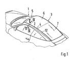
- a part of a motor vehicle is shown in perspective, in which between a roof spar 2 and a roof 3 over the entire length of the roof extending gap 4 is provided.
- the roof 3 is in the embodiment in front, adjoining the windshield frame 5 by a Large sliding glass roof 6 formed, which is a rigid towards the rear or a pivotable glass roof section 7 connects.
- Each roof side rail 2 is composed of at least two sheet metal pressed parts 8, 9, the at the angled mounting flanges 10, 11 by welding are interconnected. As can be seen further from FIGS. 4 and 5, the gap is 4th covered by a cover strip 12, the length of several of them spaced-apart holding bodies 13 is received.
- the cover strip 12 is at its two lateral edges with attached sealing strips 14, 15, wherein both sealing strips 14, 15 each have a receiving section 16, 17th and have a sealing lip 18, 19.
- the sealing lip 18 lies on the roof side rail 2 and the sealing lip 19 rests on the roof 3 under prestress.
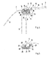
- each holding body 13 comprises a lower part 20 and an upper part 21 which on a common longitudinal edge 22 of the gap 4 over one in the longitudinal direction of the gap extending axis of rotation 23 are articulated and that the upper part 21st of the holding body 13 via a device 24 - seen in the transverse direction of the gap 4 - is incline adjustable.
- the common longitudinal edge 22 is in the Embodiment facing the roof side rail 2.
- Each holding body 13 is preferably made of plastic.
- the body side In the exemplary embodiment, the holding body 13 is fastened by gluing, wherein between the underside of the lower part 20 and the mounting flange 10 of the Roof side spar 2, an adhesive body 25 is arranged.
- the definition of the holding body 13 can also be done by screwing, clipping or the like.
- To hold the Cover strip 12 are arranged in pairs on the upper part 21 of the holding body 13, according to resilient snap hooks 26 projecting at the top and having undercuts Edge areas 27 of the cover strip 12 interact in a latching manner (FIG. 5).
- the lower part 20 and the upper part 21 of the holding body 13 are over one Film hinge 28 connected to each other, which forms the axis of rotation 23.
- the axis of rotation 23 lies slightly higher than the upper boundary surface 30 of the upper part 21.
- Das Film hinge 28 preferably extends the entire length of the The longer side of the holding body 13, which is approximately rectangular in plan view.
- the step-like, inclination-adjustable device 24 is replaced by at least one mutual locking teeth 31 formed by the upper part 21 and lower part 20, the Latching teeth 31 removed from the axis of rotation 23 of the film hinge 28 is arranged.
- the upper part 21 and the lower part 20 of the Holding body 13 each two interacting, spaced apart Lock teeth 31 provided.
- two are at a distance on the lower part 20 mutually extending upwardly projecting resilient webs 32 formed on the are provided on the outside with a star-shaped external toothing 33.
- the two webs 32 run - seen in plan view - slightly wedge-shaped to each other This means that their distance from one another is greater at the longitudinal edge 34 of the lower part 20 than at theirs inner ends 35.
- the resilient webs 32 are approximately at right angles to the longitudinal extent of the Film hinge 28 aligned.
- Each external toothing 33 acts with one correspondingly formed internal teeth 36 of the upper part 21 together.
- the internal toothings 36 are roof-shaped on the lateral wall sections 37 upward expression 38 of the upper part 21 is provided.
- a locking wedge 39 can be used to fix the upper part 21 in the desired position is in the Lower part 20 in the space between the two resilient webs 32 from the longitudinal edge 34 forth.
- the safety wedge 39 is against falling out secured.
Landscapes
- Engineering & Computer Science (AREA)
- Mechanical Engineering (AREA)
- Connection Of Plates (AREA)
- Automobile Manufacture Line, Endless Track Vehicle, Trailer (AREA)
- Registering, Tensioning, Guiding Webs, And Rollers Therefor (AREA)
- Vehicle Interior And Exterior Ornaments, Soundproofing, And Insulation (AREA)
Abstract
Description
Es zeigt:
- Fig. 1
- eine perspektivische Seitenansicht eines Kraftfahrzeuges mit einem Dachspalt und einer von Haltekörpern gehaltenen Abdeckleiste,
- Fig. 2
- eine perspektivische Ansicht eines Haltekörpers für die Abdeckleiste in eingestellter Montagestellung,
- Fig. 3
- eine perspektivische Ansicht des Haltekörpers in aufgeklappter Stellung,
- Fig. 4
- einen Schnitt nach der Linie IV-IV der Fig. 1 in größerer Darstellung und
- Fig. 5
- einen Schnitt nach der Linie V-V der Fig. 1 in größerer Darstellung.
Claims (11)
- Befestigungsvorrichtung für eine Abdeckleiste eines Spaltes an einem Kraftfahrzeug mit einem in den Spalt einsetzbaren, die Abdeckleiste aufnehmenden mehrteiligen Haltekörper, dadurch gekennzeichnet, daß der Haltekörper (13) ein Unterteil (20) und ein Oberteil (21) umfaßt, die an einem gemeinsamen Längsrand (22) über eine in Spaltlängsrichtung verlaufende Drehachse (23) gelenkig miteinander verbunden sind und daß das Oberteil (21) des Haltekörpers (13) gegenüber dem Unterteil (20) über eine Einrichtung (24) - in Querrichtung des Spaltes (10) - neigungseinstellbar ausgebildet ist.
- Befestigungsvorrichtung nach Anspruch 1, dadurch gekennzeichnet, daß das Unterteil (20) mit dem Oberteil (21) des Haltekörpers (13) über ein Filmgelenkscharnier (28) verbunden ist.
- Befestigungsvorrichtung nach Anspruch 1, dadurch gekennzeichnet, daß die Einrichtung (24) durch zumindest eine gegenseitige Rastverzahnung (31) von Oberteil (21) und Unterteil (20) gebildet wird, wobei die Rastverzahnung (31) entfernt von der Drehachse (23) des Filmgelenkscharniers (28) angeordnet ist.
- Befestigungsvorrichtung nach Anspruch 3, dadurch gekennzeichnet, daß am Unterteil (20) und am Oberteil (21) des Haltekörpers (13) jeweils zwei Rastverzahnungen (31) vorgesehen sind, die miteinander zusammenwirken.
- Befestigungsvorrichtung nach einem der vorangegangenen Ansprüche, dadurch gekennzeichnet, daß am Unterteil (20) zumindest ein nach oben ragender, an seiner Außenseite mit einer Außenverzahnung (33) versehener federnder Steg (32) ausgebildet ist, der annähernd rechtwinkelig zur Längserstreckung des Filmgelenkscharniers (28) ausgerichtet ist, wobei die Außenverzahnung (33) mit einer korrespondierend ausgebildeten Innenverzahnung (36) des Oberteils (21) zusammenwirkt.
- Befestigungsvorrichtung nach Anspruch 5, dadurch gekennzeichnet, daß die zumindest eine Innenverzahnung (36) an einem seitlichen Wandabschnitt (37) einer dachförmigen, nach oben gerichteten Ausprägung (38) des Oberteils (21) vorgesehen ist.
- Befestigungsvorrichtung nach einem der vorangegangenen Ansprüche, dadurch gekennzeichnet, daß am plattenförmigen Unterteil (20) des Haltekörpers (13) zwei beabstandet angeordnete, in der Draufsicht gesehen keilförmig zueinander verlaufende federnde Stege (32) mit Außenverzahnungen (33) vorgesehen sind.
- Befestigungsvorrichtung nach einem der vorangegangenen Ansprüche, dadurch gekennzeichnet, daß in das Unterteil (20) in den Freiraum zwischen den beiden federnden Stegen (32) ein Sicherungskeil (39) einsetzbar ist, der das Oberteil (21) in der gewünschten eingestellten Position festhält.
- Befestigungsvorrichtung nach einem der vorangegangenen Ansprüche, dadurch gekennzeichnet, daß der Sicherungskeil (39) gegen Herausfallen gesichert ist.
- Befestigungsvorrichtung nach einem der vorangegangenen Ansprüche, dadurch gekennzeichnet, daß das Unterteil (20) des Haltekörpers (13) durch Kleben, Verschrauben, Klipsen oder dgl. am feststehenden Aufbau des Kraftfahrzeugs (1) befestigt ist.
- Befestigungsvorrichtung nach einem der vorangegangenen Ansprüche, dadurch gekennzeichnet, daß am Oberteil (21) außerhalb der dachförmigen Ausprägung (38) paarweise angeordnete nach oben ragende Schnapphaken (26) ausgebildet sind, an denen die darüberliegende Abdeckleiste (12) festlegbar ist.
Applications Claiming Priority (2)
| Application Number | Priority Date | Filing Date | Title |
|---|---|---|---|
| DE2001153568 DE10153568C1 (de) | 2001-10-30 | 2001-10-30 | Befestigungsvorrichtung für eine Abdeckleiste |
| DE10153568 | 2001-10-30 |
Publications (3)
| Publication Number | Publication Date |
|---|---|
| EP1308349A2 true EP1308349A2 (de) | 2003-05-07 |
| EP1308349A3 EP1308349A3 (de) | 2004-06-23 |
| EP1308349B1 EP1308349B1 (de) | 2006-03-01 |
Family
ID=7704233
Family Applications (1)
| Application Number | Title | Priority Date | Filing Date |
|---|---|---|---|
| EP20020019513 Expired - Lifetime EP1308349B1 (de) | 2001-10-30 | 2002-08-31 | Befestigungsvorrichtung für eine Abdeckleiste |
Country Status (2)
| Country | Link |
|---|---|
| EP (1) | EP1308349B1 (de) |
| DE (2) | DE10153568C1 (de) |
Citations (1)
| Publication number | Priority date | Publication date | Assignee | Title |
|---|---|---|---|---|
| DE19521862A1 (de) | 1994-10-21 | 1996-04-25 | Porsche Ag | Befestigungsvorrichtung für eine Zier- bzw. Abdeckleiste |
Family Cites Families (3)
| Publication number | Priority date | Publication date | Assignee | Title |
|---|---|---|---|---|
| DE3736029A1 (de) * | 1987-10-24 | 1989-05-11 | Bayerische Motoren Werke Ag | Fahrzeugdach, insbesondere fuer einen personenkraftwagen |
| JPH09210027A (ja) * | 1996-01-31 | 1997-08-12 | Togo Seisakusho:Kk | 留め具 |
| DE29602223U1 (de) * | 1996-02-09 | 1997-03-27 | Erbslöh AG, 42553 Velbert | Dichtleiste zum dichtenden Abschließen einer Rinne, beispielsweise in oder an einem Fahrzeugdach |
-
2001
- 2001-10-30 DE DE2001153568 patent/DE10153568C1/de not_active Expired - Fee Related
-
2002
- 2002-08-31 DE DE50205917T patent/DE50205917D1/de not_active Expired - Lifetime
- 2002-08-31 EP EP20020019513 patent/EP1308349B1/de not_active Expired - Lifetime
Patent Citations (1)
| Publication number | Priority date | Publication date | Assignee | Title |
|---|---|---|---|---|
| DE19521862A1 (de) | 1994-10-21 | 1996-04-25 | Porsche Ag | Befestigungsvorrichtung für eine Zier- bzw. Abdeckleiste |
Also Published As
| Publication number | Publication date |
|---|---|
| EP1308349B1 (de) | 2006-03-01 |
| DE10153568C1 (de) | 2003-02-06 |
| DE50205917D1 (de) | 2006-04-27 |
| EP1308349A3 (de) | 2004-06-23 |
Similar Documents
| Publication | Publication Date | Title |
|---|---|---|
| EP1084655B1 (de) | Befestigungsanordnung | |
| EP0786398B1 (de) | Kraftfahrzeug mit einer Karosserietragstruktur und Montagelehre | |
| EP0380013B1 (de) | Vorrichtung zur Befestigung eines Dachhimmels einer Schiebedach- oder Schiebehebedachkonstruktion | |
| EP0253967B1 (de) | Stossfänger für Fahrzeuge | |
| EP0708001B1 (de) | Befestigungsvorrichtung für eine Zier- bzw. Abdeckleiste | |
| DE2715986A1 (de) | Flexible blende an stossfaengern fuer kraftfahrzeuge | |
| EP0596306B1 (de) | Abdeckleiste für eine in ein Fahrzeugdach eingelassene Rinne | |
| DE19735818C2 (de) | Befestigungsvorrichtung für eine Scheibenwischeranlage eines Kraftfahrzeuges | |
| EP1406779A1 (de) | Fensterdichtungsprofil für ein kabriolett | |
| EP1088704B1 (de) | Flächiges Karosserieteil mit einem Lastenträger für ein Fahrzeug | |
| DE3902399A1 (de) | Zierleistenhalter | |
| DE29722214U1 (de) | Abdeckkappe für ein Airbagmodul | |
| EP1348585B1 (de) | Verfahrbarer Deckel für Fahrzeugdach sowie Schiebehebedach-Modul | |
| EP1487688A1 (de) | Aus kunststoff bestehender kotflügel eines kraftfahrzeugs und befestigungsvorrichtung desselben | |
| DE19533157A1 (de) | Befestigungsanordnung einer Reling auf einem Fahrzeugdach | |
| DE19616958A1 (de) | Stoßfängerverkleidung | |
| DE10153568C1 (de) | Befestigungsvorrichtung für eine Abdeckleiste | |
| EP0531720B1 (de) | Befestigungssystem für sichtbare Anbauteile bei Fahrzeugen, insbesondere Kraftfahrzeugen | |
| DE4126442C1 (de) | ||
| DE4232192C2 (de) | Seitenverkleidung für Kraftfahrzeuge | |
| DE29921498U1 (de) | Spurfugenabdeckung für Gelenkfahrzeuge | |
| DE3606812A1 (de) | Verkleidung fuer einen einstiegsschweller eines kraftfahrzeugs | |
| DE3623073A1 (de) | Befestigungselement fuer die schraubenlose befestigung zweier bauteile | |
| DE19654446C2 (de) | Kraftfahrzeug mit einer Karosserietragstruktur und Montagelehre | |
| DE4418528C1 (de) | Dachreling für Fahrzeuge |
Legal Events
| Date | Code | Title | Description |
|---|---|---|---|
| PUAI | Public reference made under article 153(3) epc to a published international application that has entered the european phase |
Free format text: ORIGINAL CODE: 0009012 |
|
| AK | Designated contracting states |
Designated state(s): AT BE BG CH CY CZ DE DK EE ES FI FR GB GR IE IT LI LU MC NL PT SE SK TR |
|
| AX | Request for extension of the european patent |
Extension state: AL LT LV MK RO SI |
|
| PUAL | Search report despatched |
Free format text: ORIGINAL CODE: 0009013 |
|
| AK | Designated contracting states |
Kind code of ref document: A3 Designated state(s): AT BE BG CH CY CZ DE DK EE ES FI FR GB GR IE IT LI LU MC NL PT SE SK TR |
|
| AX | Request for extension of the european patent |
Extension state: AL LT LV MK RO SI |
|
| 17P | Request for examination filed |
Effective date: 20041223 |
|
| AKX | Designation fees paid |
Designated state(s): DE FR GB IT |
|
| 17Q | First examination report despatched |
Effective date: 20050502 |
|
| GRAP | Despatch of communication of intention to grant a patent |
Free format text: ORIGINAL CODE: EPIDOSNIGR1 |
|
| GRAS | Grant fee paid |
Free format text: ORIGINAL CODE: EPIDOSNIGR3 |
|
| GRAA | (expected) grant |
Free format text: ORIGINAL CODE: 0009210 |
|
| AK | Designated contracting states |
Kind code of ref document: B1 Designated state(s): DE FR GB IT |
|
| REG | Reference to a national code |
Ref country code: GB Ref legal event code: FG4D Free format text: NOT ENGLISH |
|
| REF | Corresponds to: |
Ref document number: 50205917 Country of ref document: DE Date of ref document: 20060427 Kind code of ref document: P |
|
| GBT | Gb: translation of ep patent filed (gb section 77(6)(a)/1977) |
Effective date: 20060406 |
|
| ET | Fr: translation filed | ||
| PLBE | No opposition filed within time limit |
Free format text: ORIGINAL CODE: 0009261 |
|
| STAA | Information on the status of an ep patent application or granted ep patent |
Free format text: STATUS: NO OPPOSITION FILED WITHIN TIME LIMIT |
|
| 26N | No opposition filed |
Effective date: 20061204 |
|
| REG | Reference to a national code |
Ref country code: FR Ref legal event code: TP |
|
| REG | Reference to a national code |
Ref country code: FR Ref legal event code: CD |
|
| PGFP | Annual fee paid to national office [announced via postgrant information from national office to epo] |
Ref country code: IT Payment date: 20100824 Year of fee payment: 9 |
|
| PGFP | Annual fee paid to national office [announced via postgrant information from national office to epo] |
Ref country code: GB Payment date: 20100819 Year of fee payment: 9 |
|
| REG | Reference to a national code |
Ref country code: FR Ref legal event code: TP |
|
| REG | Reference to a national code |
Ref country code: GB Ref legal event code: 732E Free format text: REGISTERED BETWEEN 20110310 AND 20110316 |
|
| REG | Reference to a national code |
Ref country code: GB Ref legal event code: 732E Free format text: REGISTERED BETWEEN 20110331 AND 20110406 |
|
| PGFP | Annual fee paid to national office [announced via postgrant information from national office to epo] |
Ref country code: FR Payment date: 20110901 Year of fee payment: 10 |
|
| GBPC | Gb: european patent ceased through non-payment of renewal fee |
Effective date: 20110831 |
|
| PG25 | Lapsed in a contracting state [announced via postgrant information from national office to epo] |
Ref country code: IT Free format text: LAPSE BECAUSE OF NON-PAYMENT OF DUE FEES Effective date: 20110831 |
|
| PG25 | Lapsed in a contracting state [announced via postgrant information from national office to epo] |
Ref country code: GB Free format text: LAPSE BECAUSE OF NON-PAYMENT OF DUE FEES Effective date: 20110831 |
|
| REG | Reference to a national code |
Ref country code: FR Ref legal event code: ST Effective date: 20130430 |
|
| PG25 | Lapsed in a contracting state [announced via postgrant information from national office to epo] |
Ref country code: FR Free format text: LAPSE BECAUSE OF NON-PAYMENT OF DUE FEES Effective date: 20120831 |
|
| PGFP | Annual fee paid to national office [announced via postgrant information from national office to epo] |
Ref country code: DE Payment date: 20150814 Year of fee payment: 14 |
|
| REG | Reference to a national code |
Ref country code: DE Ref legal event code: R119 Ref document number: 50205917 Country of ref document: DE |
|
| PG25 | Lapsed in a contracting state [announced via postgrant information from national office to epo] |
Ref country code: DE Free format text: LAPSE BECAUSE OF NON-PAYMENT OF DUE FEES Effective date: 20170301 |