EP1308314B1 - Axle unit for driving a vehicle wheel - Google Patents
Axle unit for driving a vehicle wheel Download PDFInfo
- Publication number
- EP1308314B1 EP1308314B1 EP03002281A EP03002281A EP1308314B1 EP 1308314 B1 EP1308314 B1 EP 1308314B1 EP 03002281 A EP03002281 A EP 03002281A EP 03002281 A EP03002281 A EP 03002281A EP 1308314 B1 EP1308314 B1 EP 1308314B1
- Authority
- EP
- European Patent Office
- Prior art keywords
- ring
- splined
- hub
- axially
- face
- Prior art date
- Legal status (The legal status is an assumption and is not a legal conclusion. Google has not performed a legal analysis and makes no representation as to the accuracy of the status listed.)
- Expired - Lifetime
Links
Images


Classifications
-
- B—PERFORMING OPERATIONS; TRANSPORTING
- B60—VEHICLES IN GENERAL
- B60B—VEHICLE WHEELS; CASTORS; AXLES FOR WHEELS OR CASTORS; INCREASING WHEEL ADHESION
- B60B27/00—Hubs
-
- B—PERFORMING OPERATIONS; TRANSPORTING
- B60—VEHICLES IN GENERAL
- B60B—VEHICLE WHEELS; CASTORS; AXLES FOR WHEELS OR CASTORS; INCREASING WHEEL ADHESION
- B60B27/00—Hubs
- B60B27/0005—Hubs with ball bearings
-
- B—PERFORMING OPERATIONS; TRANSPORTING
- B60—VEHICLES IN GENERAL
- B60B—VEHICLE WHEELS; CASTORS; AXLES FOR WHEELS OR CASTORS; INCREASING WHEEL ADHESION
- B60B27/00—Hubs
- B60B27/0015—Hubs for driven wheels
- B60B27/0021—Hubs for driven wheels characterised by torque transmission means from drive axle
- B60B27/0026—Hubs for driven wheels characterised by torque transmission means from drive axle of the radial type, e.g. splined key
-
- B—PERFORMING OPERATIONS; TRANSPORTING
- B60—VEHICLES IN GENERAL
- B60B—VEHICLE WHEELS; CASTORS; AXLES FOR WHEELS OR CASTORS; INCREASING WHEEL ADHESION
- B60B27/00—Hubs
- B60B27/0015—Hubs for driven wheels
- B60B27/0036—Hubs for driven wheels comprising homokinetic joints
- B60B27/0042—Hubs for driven wheels comprising homokinetic joints characterised by the fixation of the homokinetic joint to the hub
-
- B—PERFORMING OPERATIONS; TRANSPORTING
- B60—VEHICLES IN GENERAL
- B60B—VEHICLE WHEELS; CASTORS; AXLES FOR WHEELS OR CASTORS; INCREASING WHEEL ADHESION
- B60B27/00—Hubs
- B60B27/0073—Hubs characterised by sealing means
-
- B—PERFORMING OPERATIONS; TRANSPORTING
- B60—VEHICLES IN GENERAL
- B60B—VEHICLE WHEELS; CASTORS; AXLES FOR WHEELS OR CASTORS; INCREASING WHEEL ADHESION
- B60B27/00—Hubs
- B60B27/0078—Hubs characterised by the fixation of bearings
- B60B27/0084—Hubs characterised by the fixation of bearings caulking to fix inner race
-
- B—PERFORMING OPERATIONS; TRANSPORTING
- B60—VEHICLES IN GENERAL
- B60B—VEHICLE WHEELS; CASTORS; AXLES FOR WHEELS OR CASTORS; INCREASING WHEEL ADHESION
- B60B27/00—Hubs
- B60B27/0094—Hubs one or more of the bearing races are formed by the hub
-
- F—MECHANICAL ENGINEERING; LIGHTING; HEATING; WEAPONS; BLASTING
- F16—ENGINEERING ELEMENTS AND UNITS; GENERAL MEASURES FOR PRODUCING AND MAINTAINING EFFECTIVE FUNCTIONING OF MACHINES OR INSTALLATIONS; THERMAL INSULATION IN GENERAL
- F16C—SHAFTS; FLEXIBLE SHAFTS; ELEMENTS OR CRANKSHAFT MECHANISMS; ROTARY BODIES OTHER THAN GEARING ELEMENTS; BEARINGS
- F16C33/00—Parts of bearings; Special methods for making bearings or parts thereof
- F16C33/72—Sealings
- F16C33/76—Sealings of ball or roller bearings
- F16C33/768—Sealings of ball or roller bearings between relatively stationary parts, i.e. static seals
-
- F—MECHANICAL ENGINEERING; LIGHTING; HEATING; WEAPONS; BLASTING
- F16—ENGINEERING ELEMENTS AND UNITS; GENERAL MEASURES FOR PRODUCING AND MAINTAINING EFFECTIVE FUNCTIONING OF MACHINES OR INSTALLATIONS; THERMAL INSULATION IN GENERAL
- F16C—SHAFTS; FLEXIBLE SHAFTS; ELEMENTS OR CRANKSHAFT MECHANISMS; ROTARY BODIES OTHER THAN GEARING ELEMENTS; BEARINGS
- F16C35/00—Rigid support of bearing units; Housings, e.g. caps, covers
- F16C35/04—Rigid support of bearing units; Housings, e.g. caps, covers in the case of ball or roller bearings
- F16C35/06—Mounting or dismounting of ball or roller bearings; Fixing them onto shaft or in housing
- F16C35/063—Fixing them on the shaft
- F16C35/0635—Fixing them on the shaft the bore of the inner ring being of special non-cylindrical shape which co-operates with a complementary shape on the shaft, e.g. teeth, polygonal sections
-
- F—MECHANICAL ENGINEERING; LIGHTING; HEATING; WEAPONS; BLASTING
- F16—ENGINEERING ELEMENTS AND UNITS; GENERAL MEASURES FOR PRODUCING AND MAINTAINING EFFECTIVE FUNCTIONING OF MACHINES OR INSTALLATIONS; THERMAL INSULATION IN GENERAL
- F16C—SHAFTS; FLEXIBLE SHAFTS; ELEMENTS OR CRANKSHAFT MECHANISMS; ROTARY BODIES OTHER THAN GEARING ELEMENTS; BEARINGS
- F16C35/00—Rigid support of bearing units; Housings, e.g. caps, covers
- F16C35/04—Rigid support of bearing units; Housings, e.g. caps, covers in the case of ball or roller bearings
- F16C35/06—Mounting or dismounting of ball or roller bearings; Fixing them onto shaft or in housing
- F16C35/07—Fixing them on the shaft or housing with interposition of an element
- F16C35/073—Fixing them on the shaft or housing with interposition of an element between shaft and inner race ring
-
- F—MECHANICAL ENGINEERING; LIGHTING; HEATING; WEAPONS; BLASTING
- F16—ENGINEERING ELEMENTS AND UNITS; GENERAL MEASURES FOR PRODUCING AND MAINTAINING EFFECTIVE FUNCTIONING OF MACHINES OR INSTALLATIONS; THERMAL INSULATION IN GENERAL
- F16C—SHAFTS; FLEXIBLE SHAFTS; ELEMENTS OR CRANKSHAFT MECHANISMS; ROTARY BODIES OTHER THAN GEARING ELEMENTS; BEARINGS
- F16C41/00—Other accessories, e.g. devices integrated in the bearing not relating to the bearing function as such
- F16C41/007—Encoders, e.g. parts with a plurality of alternating magnetic poles
-
- F—MECHANICAL ENGINEERING; LIGHTING; HEATING; WEAPONS; BLASTING
- F16—ENGINEERING ELEMENTS AND UNITS; GENERAL MEASURES FOR PRODUCING AND MAINTAINING EFFECTIVE FUNCTIONING OF MACHINES OR INSTALLATIONS; THERMAL INSULATION IN GENERAL
- F16C—SHAFTS; FLEXIBLE SHAFTS; ELEMENTS OR CRANKSHAFT MECHANISMS; ROTARY BODIES OTHER THAN GEARING ELEMENTS; BEARINGS
- F16C19/00—Bearings with rolling contact, for exclusively rotary movement
- F16C19/02—Bearings with rolling contact, for exclusively rotary movement with bearing balls essentially of the same size in one or more circular rows
- F16C19/14—Bearings with rolling contact, for exclusively rotary movement with bearing balls essentially of the same size in one or more circular rows for both radial and axial load
- F16C19/18—Bearings with rolling contact, for exclusively rotary movement with bearing balls essentially of the same size in one or more circular rows for both radial and axial load with two or more rows of balls
- F16C19/181—Bearings with rolling contact, for exclusively rotary movement with bearing balls essentially of the same size in one or more circular rows for both radial and axial load with two or more rows of balls with angular contact
- F16C19/183—Bearings with rolling contact, for exclusively rotary movement with bearing balls essentially of the same size in one or more circular rows for both radial and axial load with two or more rows of balls with angular contact with two rows at opposite angles
- F16C19/184—Bearings with rolling contact, for exclusively rotary movement with bearing balls essentially of the same size in one or more circular rows for both radial and axial load with two or more rows of balls with angular contact with two rows at opposite angles in O-arrangement
- F16C19/185—Bearings with rolling contact, for exclusively rotary movement with bearing balls essentially of the same size in one or more circular rows for both radial and axial load with two or more rows of balls with angular contact with two rows at opposite angles in O-arrangement with two raceways provided integrally on a part other than a race ring, e.g. a shaft or housing
-
- F—MECHANICAL ENGINEERING; LIGHTING; HEATING; WEAPONS; BLASTING
- F16—ENGINEERING ELEMENTS AND UNITS; GENERAL MEASURES FOR PRODUCING AND MAINTAINING EFFECTIVE FUNCTIONING OF MACHINES OR INSTALLATIONS; THERMAL INSULATION IN GENERAL
- F16C—SHAFTS; FLEXIBLE SHAFTS; ELEMENTS OR CRANKSHAFT MECHANISMS; ROTARY BODIES OTHER THAN GEARING ELEMENTS; BEARINGS
- F16C19/00—Bearings with rolling contact, for exclusively rotary movement
- F16C19/02—Bearings with rolling contact, for exclusively rotary movement with bearing balls essentially of the same size in one or more circular rows
- F16C19/14—Bearings with rolling contact, for exclusively rotary movement with bearing balls essentially of the same size in one or more circular rows for both radial and axial load
- F16C19/18—Bearings with rolling contact, for exclusively rotary movement with bearing balls essentially of the same size in one or more circular rows for both radial and axial load with two or more rows of balls
- F16C19/181—Bearings with rolling contact, for exclusively rotary movement with bearing balls essentially of the same size in one or more circular rows for both radial and axial load with two or more rows of balls with angular contact
- F16C19/183—Bearings with rolling contact, for exclusively rotary movement with bearing balls essentially of the same size in one or more circular rows for both radial and axial load with two or more rows of balls with angular contact with two rows at opposite angles
- F16C19/184—Bearings with rolling contact, for exclusively rotary movement with bearing balls essentially of the same size in one or more circular rows for both radial and axial load with two or more rows of balls with angular contact with two rows at opposite angles in O-arrangement
- F16C19/186—Bearings with rolling contact, for exclusively rotary movement with bearing balls essentially of the same size in one or more circular rows for both radial and axial load with two or more rows of balls with angular contact with two rows at opposite angles in O-arrangement with three raceways provided integrally on parts other than race rings, e.g. third generation hubs
-
- F—MECHANICAL ENGINEERING; LIGHTING; HEATING; WEAPONS; BLASTING
- F16—ENGINEERING ELEMENTS AND UNITS; GENERAL MEASURES FOR PRODUCING AND MAINTAINING EFFECTIVE FUNCTIONING OF MACHINES OR INSTALLATIONS; THERMAL INSULATION IN GENERAL
- F16C—SHAFTS; FLEXIBLE SHAFTS; ELEMENTS OR CRANKSHAFT MECHANISMS; ROTARY BODIES OTHER THAN GEARING ELEMENTS; BEARINGS
- F16C2326/00—Articles relating to transporting
- F16C2326/01—Parts of vehicles in general
- F16C2326/02—Wheel hubs or castors
Landscapes
- Engineering & Computer Science (AREA)
- Mechanical Engineering (AREA)
- General Engineering & Computer Science (AREA)
- Rolling Contact Bearings (AREA)
- Arrangement And Driving Of Transmission Devices (AREA)
Description
- The present invention relates to an axle unit for driving a vehicle wheel as described in the preamble of
claim 1. - Various kinds of axle units have heretofore been used, in which an outer ring and an inner ring are rotatably combined via rolling members in order to rotatably support a wheel on a suspension unit. It is necessary for the axle unit used for supporting the driven wheel on the independent suspension and rotatably driving the driven wheel, to smoothly transmit the rotation of the drive shaft to the wheel (while ensuring constant velocity); in combination with a constant velocity joint, regardless of relative displacement between the differential gear and the driven wheel and the steering angle imparted to the wheel. The axle unit for driving the vehicle wheel, which is a so-called fourth generation hub unit, can be combined with such a constant velocity joint and can be constructed relatively compact and lightweight. Such an axle unit has heretofore been disclosed in Japanese Patent Publication Tokukai Hei No. 7-317754, in US Patent No. 5,674,011, or in US 4 881 842, which comprises the features mentionned in the preamble of
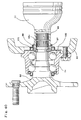
claim 1. - FIG. 36 shows one example of a conventional construction disclosed in Japanese Patent Publication Tokukai Hei No. 7-317754. An
outer ring 1 which does not rotate while being supported on the suspension unit when incorporated into the vehicle, has an outward flange shapedattachment portion 2 for supporting the outer ring on the suspension unit, on the outer peripheral face thereof, and two rows ofouter ring raceways 3 on the inner peripheral face thereof. - On the radially inner side of the
outer ring 1, ahub 6 formed by combining afirst element 4 and asecond element 5 is disposed. Of these, thefirst element 4 is formed in a cylindrical form having anmount flange 7 for supporting the wheel on one end side (on the left end side in FIG. 36), and aninner ring raceway 8 on the other end side (on the right end side in FIG. 36). Thesecond element 5 has on one end side (the left end side in FIG. 36) acylindrical portion 9 for externally securing thefirst element 4, and on the other end side (the right end side in FIG. 36) ahousing 11 which is the outer ring of aconstant velocity joint 10 of a Rzeppa type, with theinner ring raceway 8 arranged on the outer peripheral face of the middle part thereof. - By disposing a plurality of
rolling members 12, respectively between theouter ring raceways 3 and theinner ring raceways 8, thehub 6 is rotatably supported on the inside of theouter ring 1. - In a position where the inner peripheral face of the
first element 4 and the outer peripheral face of thesecond element 5 are joined in an aligned manner, anoutside engagement groove 13 and aninside engagement groove 14 are respectively formed, and astop ring 15 is provided between and engaged into theseengagement grooves first element 1 from coming away from thesecond element 5. - Moreover, a
weld 17 is applied between an outer peripheral rim portion on one end face (the left end face in FIG. 36) of thesecond element 5 and an inner peripheral rim portion of astepped portion 16 formed on the inner peripheral face of thefirst element 4, to securely connect the first andsecond elements - Furthermore, substantially
cylindrical covers 18 made of metal such as stainless steel plate, andcircular seal rings 19 made of a resilient material such as rubber or elastomer are provided between the opening portions at opposite ends of theouter ring 1 and the outer peripheral face in the middle part of thehub 6. On the inside of the middle part of thesecond element 5, anisolating member 20 for closing off the inside of thesecond element 5 is provided. These covers 18,seal rings 19 and isolatingmember 20 shut off the portion where the plurality ofrolling members 12 are installed, or the portion ofconstant velocity joint 10, from outside, and prevent grease existing inside the portion from leaking to the outside as well as preventing the ingress of foreign matter such as rainwater, dust or the like. - The
constant velocity joint 10 comprises thehousing 11, aninner ring 21, aretainer 22 and a plurality ofballs 23. Theinner ring 21 is fixed to a tip end of a drive shaft (not shown) which is rotatably driven via a transmission by an engine. On the outer peripheral face of thisinner ring 21, there are respectively formed in a direction at right angles to the circumferential direction, sixinner engagement grooves 24 having a section of an arc when cut on a virtual plane orthogonal to the central axis of theinner ring 21, at even spacing in the circumferential direction. - At a position opposite to the
inner engagement grooves 24 on the inner peripheral face of thehousing 11, there are similarly formed respectively in a direction at right angles to the circumferential direction, sixouter engagement grooves 25 having a section of an arc. - The
retainer 22 is formed in an overall annular shape, having a section of an arc, and is held between the outer peripheral face of theinner ring 21 and the inner peripheral face of thehousing 11.Pockets 26 are respectively formed in theretainer 22 at the six positions in the circumferential direction thereof, being positions aligned with the inside andoutside engagement grooves pockets 26. Theseballs 23 can be freely rolled along the inside andoutside engagement grooves pocket 26, respectively. - When the axle unit for driving the vehicle wheel constructed as described above is fitted to a vehicle, the
outer ring 1 is supported on the suspension unit by theattachment portion 2, and the driven wheel is fixed to thefirst element 4 by themount flange 7. - The drive shaft (not shown) is rotatably driven via the transmission by the engine, and the tip portion of the drive shaft is spline-engaged to the inside of the
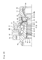
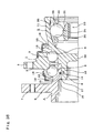
inner ring 21 of theconstant velocity joint 10. At the time of driving an automobile, the rotation of theinner ring 21 is transmitted to thehub 6 including thesecond element 5 via the plurality ofballs 23 to rotatably drive the driven wheel. - FIG. 37 shows a second example of a conventional construction which is disclosed in the abovementioned US Patent No. 5,674,011. In the case of the second example of conventional construction, two rows of
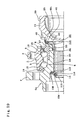
outer ring raceways 3 are disposed on the inner peripheral face of theouter ring 1 which does not rotate at the time of use, being internally fixed to aknuckle 40 of a suspension unit. - A
mount flange 7 for supporting the wheel, is disposed on one end side (on the left end side in FIG. 37) of the outer peripheral face of thehub 6a, and two rows ofinner ring raceways 8 are disposed on the other end side (on the right end side in FIG. 37) via a pair ofinner rings 50. Theinner rings 50 are supported and secured to the body of thehub 6a by means of a crimpedportion 27 formed by bending the other end of thehub 6a radially outward. - A plurality of rolling
members 12 are respectively disposed between theouter ring raceways 3 and theinner ring raceways 8 to rotatably support thehub 6a inside of theouter ring 1. - A
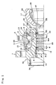
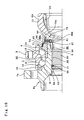
splined bore 28 is provided in the central portion of thehub 6a. Thehub 6a and adrive shaft member 29 are thus combined to form an axle unit for driving a vehicle wheel. On one end side of thedrive shaft member 29, there is provided asplined shaft 30 engaging with thesplined bore 28. In addition, on the other end side of thedrive shaft member 29 is ahousing 11 which is the outer ring of the constant velocity joint. Thedrive shaft member 29 and thehub 6a are combined together such that thesplined shaft 30 is inserted into thesplined bore 28, and acoupling member 31 made of a resilient material is interlockingly engaged with themembers coupling member 31 is provided withencoders 32 made of a magnetic material or a permanent magnet to make it possible to detect the rotation speed of the twomembers - FIG. 38 shows a third example of a conventional construction which is disclosed in Japanese Utility Model Registration No. 2,573,325. In the case of the third example of conventional construction, a
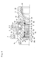
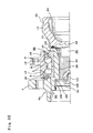
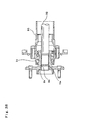
hub 6b is spline-engaged with a portion of an end of anaxle 92 exposed from the end of anaxle pipe 93. Thehub 6b is rotatably supported by rolling members arranged in two rows inside of a fixed outer ring 1a. - In addition, a
stop ring 15a in the form of a segment circle is engaged in anengagement groove 94 formed in the tip portion of theaxle 92 at a portion projecting from the spline engagement with thehub 6b, to prevent thehub 6b from coming out from theaxle 92. - FIG. 39 shows a fourth example of a conventional construction which is disclosed in US Patent No. 4,881,842. In the case of the fourth example of conventional construction, a
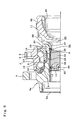
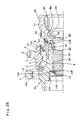
hub 6c is rotatably supported by two rows of rolling members inside of anouter ring 1b fixed to aknuckle 40. - A
splined shaft 30 is spline-engaged with asplined bore 28 formed in the central portion of thehub 6c. In addition, ahousing 11 which is the outer ring of the constant velocity joint is disposed on the base end (the right end in FIG. 39) of thesplined shaft 30. On the tip end face (the left end face in FIG. 39) of thesplined shaft 30, is formed anattachment portion 95 for engaging with a tool for pulling thesplined shaft 30 into thesplined bore 28. - The
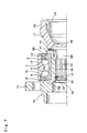
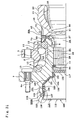
hub 6c is prevented from coming out from thesplined shaft 30 by astop ring 15b fitted in the engagement groove formed in a portion on the tip end side on the outer peripheral face of thesplined shaft 30. In this condition, aresilient ring 96 is resiliently compressed between thehub 6c and thehousing 11 to prevent play of thehub 6c on thesplined shaft 30. - FIG. 40 shows a fifth example of a conventional construction which is disclosed in US Patent No. 5,492,417. In the case of the fifth example of conventional construction, a
hub 6d is rotatably supported by two rows of rolling members inside of an outer ring 1c fixed to aknuckle 40. Aninner ring 50 externally fitted to thehub 6d is prevented from moving axially, with astop ring 97 fitted in thehub 6d. - In addition, the tip portion of a sleeve 98 (the left end in FIG. 40) of a constant velocity joint, which is spline-engaged with the axially inner end (the right end in FIG. 40) of the
hub 6d covers thestop ring 97 to prevent thestop ring 97 from coming off from thehub 6d. - A
stop ring 15c is positioned between and engaged with the outer peripheral face of the inner end of thehub 6d and the inner peripheral face of thesleeve 98 to prevent thehub 6d from coming out from thesleeve 98. A gear-like undulation portion 99 is formed on the outer peripheral face of the tip portion of thesleeve 98 so that this portion functions as an encoder. A rotationspeed detection sensor 101 supported on the outer ring 1c via aseal ring 100 faces theundulation portion 99 so as to detect the rotation speed of thesleeve 98 and thehub 6d. - In the case of the first example of the conventional construction shown in FIG. 36, transmission of the rotation force between the
first element 4 and thesecond element 5 which constitute thehub 6 must be effected by the portion ofweld 17. That is to say, it is necessary to transmit a large torque for driving, between thefirst element 4 for supporting the wheel and thesecond element 5 coupled to the drive shaft. - However, since these
elements weld 17. Hence theweld 17 needs to be a full peripheral built up weld in order to increase the strength of the portion ofweld 17 sufficiently. When theweld 17 is a built up weld around the whole periphery however, the shape of the portion ofinner ring raceway 8 formed on the outer peripheral face of thefirst element 4 may be distorted, or the hardness of the portion ofinner ring raceway 8 may be decreased, due to the heat at the time of welding. Hence the durability of the rolling bearing unit including thisinner ring raceways 8 cannot be sufficiently ensured. - In the case of the second example of the conventional construction shown in FIG. 37, since the separation between the
hub 6a and thedrive shaft member 29 is prevented by thecoupling member 31 made of a resilient material, the function of preventing the separation is rather uncertain. That is to say, when an automobile turns abruptly, a large cornering force is applied to thehub 6a in the direction of pulling thishub 6a away from thedrive shaft member 29, based on the large thrust load due to a centrifugal force applied to thehub 6a from the wheel. Therefore in the case of such a large force it is very difficult to reliably prevent the separation of thehub 6a from thedrive shaft member 29, by means of thecoupling member 31. Hence sufficient reliability cannot be ensured. - The third example of the conventional construction shown in FIG. 38 relates to a so-called semi-floating type construction which is a non-independent suspension type suspension. In the case of such a construction, the splined engagement portion can be shut off from the outside space by the coupling portion of the
axle pipe 93 and the outer ring 1a. Therefore, it is not necessary to provide a sealing device between the axle and the hub to shut off the splined engagement portion from the outside space. The third example of such a conventional construction has a quite different basic construction from that of the present invention in which the driven wheel supported by an independent type suspension is rotatably supported with respect to the suspension unit. - In the case of the fourth example of the conventional construction shown in FIG. 39, a member for shutting off the splined engagement portion from the outside is not provided. Therefore, the ingress of foreign matter such as rain water containing dust into the splined engagement portion cannot be avoided. Moreover, in the case of the construction as shown in FIG. 39, in which play of the
hub 6c with respect to thesplined shaft 30 is prevented by theresilient ring 96, and theresilient ring 96 can be deformed due to axial load causing sliding motion in the splined engagement portion, and then if foreign matter enters into the splined engagement portion, the splined engagement portion is worn, and the durability is deteriorated, which is unsatisfactory. - In the case of the fifth example of the conventional construction shown in FIG. 40, since the splined engagement portion is disposed in a portion protruding inward from the inner end opening of the outer ring 1c, the axial dimension of the whole axle unit for driving the vehicle wheel is increased, and a compact and lightweight structure cannot be realized.
- The axle unit for driving the vehicle wheel according to the present invention has been developed in order to address the above-mentioned problems.
- An object of the present invention is to provide a compact and light weight axle unit with good durability and reliability for driving a vehicle wheel wherein the hub has a splined bore which is engaged with the splined shaft of the drive shaft member, and a stop ring which is held between the outer engagement groove on the inner peripheral surface of the splined bore and the inner engagement groove on the outer peripheral surface of the splined shaft to prevent the splined shaft from being removed.
-
- Fig. 1 is a cross sectional view of one half of an example of the embodiments of the axle unit for driving a vehicle wheel not being part of the invention.
- Fig. 2 is a view of a stop ring taken from one side of Fig. 1.
- Fig. 3 is a cross sectional view of one half of an example of the embodiments of the axle unit for driving a vehicle wheel not being part of the invention.
- Fig. 4 is an enlarged partial view of the stop ring in an inserted state.
- Fig. 5 is a partial view of the splined bore taken from left in Fig. 3.
- Fig. 6 is a cross sectional view of one half of an example of the embodiments of the axle unit for driving a vehicle wheel not being part of the present invention.
- Fig. 7 is a cross sectional view of one half of an example of the embodiments of the axle unit for driving a vehicle wheel not being part of the present invention.
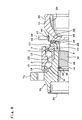
- Fig. 8 is a cross sectional view of one half of an example of the embodiments of the axle unit for driving a vehicle wheel not being part of the present invention.
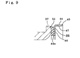
- Fig. 9 is a cross sectional view of the encoder and resilient plate.
- Fig. 10 is a cross sectional view of one half of an example of the embodiments of the axle unit for driving a vehicle wheel not being part of the present invention.
- Fig. 11 is a view of part of the backing metal member and seal lips taken from left in Fig. 10.
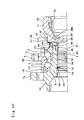
- Fig. 12 is a cross sectional view of one half of an example of the embodiments of the axle unit for driving a vehicle wheel not being part of the present invention.
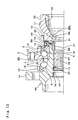
- Fig. 13 is a cross sectional view of one half of an example of the embodiments of the axle unit for driving a vehicle wheel not being part of the present invention.
- Fig. 14 is a cross sectional view of one half of an example of the embodiments of the axle unit for driving a vehicle wheel not being part of the present invention.
- Fig. 15 is a cross sectional view of one half of an example of the embodiments of the axle unit for driving a vehicle wheel not being part of the present invention.
- Fig. 16 is a cross sectional view of one half of an example of the embodiments of the axle unit for driving a vehicle wheel not being part of the present invention.
- Fig. 17 is a cross sectional view of one half of an example of the embodiments of the axle unit for driving a vehicle wheel not being part of the present invention.
- Fig. 18 is a cross sectional view of one half of an example of the embodiments of the axle unit for driving a vehicle wheel not being part of the present invention.
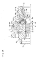
- Fig. 19 is a cross sectional view of one half of an example of the embodiments of the axle unit for driving a vehicle wheel not being part of the present invention.
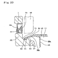
- Fig. 20 is an enlarged view of Portion XX in Fig. 19.
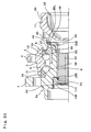
- Fig. 21 is a cross sectional view of one half of an example of the embodiments of the axle unit for driving a vehicle wheel not being part of the present invention.
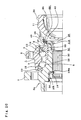
- Fig. 22 is a cross sectional view of one half of an example of the embodiments of the axle unit for driving a vehicle wheel not being part of the present invention.
- Fig. 23 is a cross sectional view of one half of an example of the embodiments of the axle unit for driving a vehicle wheel not being part of the present invention.
- Fig. 24 is a cross sectional view of one half of an example of the embodiments of the axle unit for driving a vehicle wheel not being part of the present invention.
- Fig. 25 is a enlarged perspective view of part of the stop ring in Fig. 24.
- Fig. 26 is a cross sectional view of one half of an example of the embodiments of the axle unit for driving a vehicle wheel not being part of the present invention.
- Fig. 27 is an enlarged perspective view of the stop ring in Fig. 26.
- Fig. 28 is a cross sectional view of one half of an example of the embodiments of the axle unit for driving a vehicle wheel not being part of the present invention.
- Fig. 29 is a cross sectional view of one half of an example of the embodiments of the axle unit for driving a vehicle wheel not being part of the present invention.
- Fig. 30 is a cross sectional view of one half of an example of the embodiments of the axle unit for driving a vehicle wheel not being part of the present invention.
- Fig. 31 is a cross sectional view of one half of an example of the embodiments of the axle unit for driving a vehicle wheel not being part of the present invention.
- Fig. 32 is an enlarged view of Portion XXXII in Fig. 31.
- Fig. 33 is a cross sectional view of one half of an example of the embodiments of the axle unit for driving a vehicle wheel not being part of the present invention.
- Fig. 34 is a cross sectional view of one half of an example of the embodiments of the axle unit for driving a vehicle wheel according to the present invention.
- Fig. 35 is a cross sectional view of one half of an example of the embodiments of the axle unit for driving a vehicle wheel not being part of the present invention.
- Fig. 36 is a cross sectional partial view of one example of the prior art structures.
- Fig. 37 is a cross sectional partial view of one example of the prior art structures.
- Fig. 38 is a cross sectional partial view of one example of the prior art structures.
- Fig. 39 is a cross sectional partial view of one example of the prior art structures.
- Fig. 40 is a cross sectional partial view of one example of the prior art structures.
-
- The axle unit for driving a vehicle wheel in one feature not being part of the present invention is combined with a constant velocity joint and comprises, like the axle unit for driving the vehicle wheel of the second example of the prior art structure shown in Fig. 37, an outer ring having an inner peripheral surface formed with an outer ring raceway and being not rotatable during use, a hub having an outer peripheral surface formed with a mount flange at a portion on one end side thereof to support the wheel, with an inner ring raceway at a portion on the other end side thereof, the inner ring raceway being formed directly thereon or on an inner ring thereon, and a splined bore at a central portion, a drive shaft member having a splined shaft on one end side thereof for engagement with the splined bore and a housing section on the other end side thereof, the housing section forming the outer ring of the constant velocity joint, and a plurality of rolling members provided rotatably between the outer ring raceway and the inner ring raceway.
- Particularly, in one feature not being part of the present invention, the axle unit for driving the vehicle wheel is provided with an inner engagement portion formed in the outer peripheral surface of the splined shaft in the whole circumference, an outer engagement portion formed in the inner peripheral surface of the hub in the whole circumference at the location in alignment with the inner engagement portion, and a stop ring made of a resilient member.
- The stop ring is provided between and engaged with the inner engagement portion and the outer engagement portion, so that the hub is positioned axially with reference to the drive shaft member. In addition, a seal member of resilient material is resiliently held between the hub and the drive shaft member to seal the splined engagement portion between the splined bore and the splined shaft.
- In another feature not being part of the present invention, a coupling shaft member different from the hub is provided, and the axle unit for driving the vehicle wheel is provided with an outer engagement portion formed in the inner peripheral surface of the bore formed and engaged on one end side of the splined shaft in the whole circumference, an inner engagement portion formed in the outer peripheral surface of the coupling shaft member in the whole circumference at the location in alignment with the outer engagement portion, and a stop ring made of a resilient member.
- Part of the hub is held axially from the opposite sides between part of the coupling shaft member and part of the drive shaft member and in this state, the stop ring is provided between and engaged with the inner engagement portion and the outer engagement portion, so that the hub is positioned axially with reference to the coupling shaft member and drive shaft member. In addition, a seal member of resilient material is resiliently held between the hub and the drive shaft member to seal the splined engagement portion between the splined bore and the splined shaft.
- In addition, in another feature, a coupling member different from the hub is provided, and part of the coupling member is connected to one end of the drive shaft member. With part of the coupling member and part of the drive shaft member, the hub is positioned axially with reference to the coupling member and drive shaft member. In addition, a seal member of resilient material is resiliently held between the hub and the drive shaft member to seal the splined engagement portion between the splined bore and the splined shaft.
- With the axle unit for driving the vehicle wheel, torque is transmitted between the drive shaft member and the hub based on engagement between the splined shaft and splined bore. Accordingly, any treatment such as the built up weld to securely conduct the torque transmission between the drive shaft member and the hub, that causes distortion by heat etc., is not required, so that the endurance of the rolling bearing unit parts including the inner ring raceways can be secured.
- Particularly, the hub and the drive shaft member can be prevented from being separated from each other by engagement between the inner and outer engagement portions and the stop ring, or between the inner and outer engagement portions, the stop ring and the coupling shaft member, or between the coupling member, the drive shaft member and the hub. Since the stop ring is made of a material with sufficient strength such as metals, the separation is positively prevented so as to secure the reliability of the axle unit for driving the vehicle wheel.
- In the structure not being part of the present invention, axial sliding motion occurs in the splined engagement portion, which is different from the clamping with a nut or from the connection with welding, but since the seal member of resilient material is resiliently held between the hub and the drive shaft member to isolate the splined engagement portion from outside space, foreign matter can be prevented from entering the splined engagement portion, so that wear in the splined engagement portion is prevented. As a result, the endurance of the axle unit for driving the vehicle wheel including the splined engagement portion can be improved.
- Now, some examples of the embodiments not being part of the present invention are explained with reference to the attached drawings.
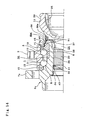
- FIGS. 1 and 2 show a first example of an embodiment not being part of the present invention. An
outer ring 1 which does not rotate while being supported on the suspension unit has anattachment portion 2 for supporting on the suspension unit, on the outer peripheral face thereof, and two rows ofouter ring raceways 3 on the inner peripheral face thereof. Ahub 6a is disposed concentrically with theouter ring 1, on the inner diameter side of theouter ring 1. -
Inner ring raceways 8 are disposed directly or on a separateinner ring 50 on the outer peripheral face of thehub 6a on a part facing the respectiveouter ring raceways 3. - The
inner ring 50 is externally fitted to a steppedportion 33 formed on the axially inner end of the main body of thehub 6a (an end portion towards the center in the width direction of the vehicle when fitted to the vehicle; the right end in FIG. 1), and is secured to thehub 6a at the axially inner end of the main body, by a crimpedportion 27 formed by upsetting and expanding a portion protruding from the axially inner end face of theinner ring 50 in a radially outward direction. - The
hub 6a is rotatably supported on the inside of theouter ring 1, by rollably providing a plurality of rollingmembers 12 between theouter ring raceways 3 and theinner ring raceways 8, respectively. - In addition, seal rings 19 are disposed between the inner peripheral face on opposite end portions of the
outer ring 1 and the outer peripheral face of the middle part of the main body of thehub 6a and the outer peripheral face of the axially inner end portion of theinner ring 50, to isolate the portion where the rollingmembers 12 are arranged from the outside space. - The outer end opening, that is at the axially outer end, of the
hub 6a is fitted and secured with acap 34 to shut off the outer end opening. On the outer peripheral face of the axially outer end of thehub 6a (the end towards the outside in the width direction of the vehicle when fitted to the vehicle; the left end in FIG. 1; corresponding to the one end described in the claims), amount flange 7 for supporting and securing the wheel to thehub 6a is provided integrally with thehub 6a. - Moreover, a
splined bore 28 is disposed in the center of thehub 6a. Thehub 6a and thedrive shaft member 29 are combined to constitute a rolling bearing unit for a wheel. Asplined shaft 30 which engages with the splined bore 28 is also disposed at the portion on the axially outer end side of thedrive shaft member 29. The portion on the axially inner end side of thedrive shaft member 29 forms ahousing 11 which is an outer ring of a constant velocity joint. - With the axle unit for driving the vehicle wheel not being part of the present invention, an inside engagement portion or inside
engagement groove 14 is formed around the whole periphery on the outer peripheral face of the middle part on the axially outer end side of thesplined shaft 30. An outside engagement portion oroutside engagement groove 13 is also formed around the whole periphery at a position aligned with theinside engagement groove 14, on the inner peripheral face of the middle part on the axially outer end side of thesplined bore 28. - Moreover, a
stop ring 35 in the form of a segment circle as shown in FIG. 2 is fitted to the inside and outsideengagement grooves stop ring 35 is provided between and engaged with theseengagement grooves - The
stop ring 35 is so formed that the diameter thereof is resiliently compressible and expandable, by forming a wire rod made of a resilient metal such as spring steel, stainless spring steel and the like in the form of an approximate C-shaped segment circle. An outer diameter D35 of thestop ring 35 in a free state should be at least a diameter R28 of the maximum inscribing circle of the splined bore 28 (the addendum circle of the splined bore 28). Moreover, a diameter R14 of the groove bottom of theinside engagement groove 14 and the diameter R13 of the groove bottom of theoutside engagement groove 13 are restricted so that thestop ring 35 is provided between and engaged with the inside and outsideengagement grooves inside engagement groove 14 is not larger than a value obtained by subtracting twice of the diameter d35 of the wire rod constituting thestop ring 35 from the diameter R28 of the maximum inscribing circle of the splined bore 28 (R14 ≦ R28 - 2d35). - Such a restriction is required to make it possible to freely insert the
splined shaft 30 together with thestop ring 35 into the splined bore 28, with thestop ring 35 pushed into the bottom of theinside engagement groove 14. - In addition, the diameter R13 should be less than a value obtained by adding twice of the diameter d35 of the wire rod constituting the
stop ring 35 to the diameter D30 of the maximum circumscribing circle of the splined shaft 30 (the addendum circle of the splined shaft 30) (R13 < D30 + 2d35). Such a restriction is required to engage the inner peripheral rim portion of thestop ring 35 with theinside engagement groove 14, with the diameter of thestop ring 35 resiliently enlarged. - Therefore, it is preferred that the diameter R13 of the groove bottom of the
outside engagement groove 13 be restricted so that thestop ring 35 exists in a central position in a diametrical direction of the engagement portion between thesplined bore 28 and thesplined shaft 30, with the outer peripheral rim of thestop ring 35 abutted against the groove bottom of theoutside engagement groove 13. - Since the dimensions of the inside and outside
engagement grooves stop ring 35 are restricted as described above, then if thesplined shaft 30 is inserted into the splined bore 28 with thestop ring 35 fitted to the portion ofinside engagement groove 14, thehub 6a and thedrive shaft member 29 can be coupled so as not to be separated. That is to say, when thehub 6a and thedrive shaft member 29 are coupled, thesplined shaft 30 is inserted into the splined bore 28 with thestop ring 35 fitted to theinside engagement groove 14, from inside toward outside, that is, from the right to the left in FIG. 1. - By this inserting action, the
stop ring 35 is guided along the inner peripheral faces of the crimpedportion 27 and of aguide face 36 formed in a conical concave shape disposed adjacent to the axially inner end portion of the splined bore 28, while resiliently compressing the outer diameter, and is pushed into thesplined bore 28. Then, the diameter of thestop ring 35 resiliently expands until the outer peripheral rim of thestop ring 35 abuts against the bottom face of theoutside engagement groove 13, with theinside engagement groove 14 and theoutside engagement groove 13 aligned. - In this way, with the diameter of the
stop ring 35 resiliently expanded, thestop ring 35 is provided between and engaged with the inside and outsideengagement grooves splined shaft 30 from coming out from the splined bore 28, and to couple thehub 6a and thedrive shaft member 29 so as not to be separated. - The tilt angle of the
guide face 36 with respect to the axial direction of thehub 6a is preferably 30 degree or less so that thestop ring 35 can smoothly pass along theguide face 36. - Furthermore, it is preferable that the engagement portion between the
splined shaft 30 and the splined bore 28 is lubricated by applying a urea type grease to the engagement portion between thesplined shaft 30 and the splined bore 28 to interpose a lubricant therebetween. The urea type grease contains an urea compound as the consistency agent and a synthetic oil as the base oil. - A width W of the inside and outside
engagement grooves stop ring 35, but the difference between the width W and the diameter d35 is made as small as possible. The reason for this is to suppress play in the coupling portion made up of the inside and outsideengagement grooves stop ring 35. - To improve the coupling strength between the
hub 6a and thedrive shaft member 29, the coupling portion made up of the inside and outsideengagement grooves stop ring 35 may be disposed in two axial positions. In this case however, the width of the inside and outsideengagement grooves stop ring 35 located on the tip end side in the insertion direction (the left end side in FIG. 1) should be larger than the width of the inside and outside engagement grooves and the diameter of the wire rod constituting the stop ring located on the rear end side in the insertion direction (the right end side in FIG. 1). - The reason for this is to prevent the stop ring of the engagement portion on the tip end side and the outside engagement groove of the engagement portion on the rear end side from engaging with each other. Otherwise, the
splined shaft 30 could not be inserted further into thesplined bore 28. - In the case of this example, a seal member or
seal ring 37 of an X-shape in cross-section is disposed between a portion located between thesplined shaft 30 and thehousing 11 on the outer peripheral face of the middle part of thedrive shaft member 29, and the inner peripheral face of the axially inner end portion of thehub 6a. Thecircular seal ring 37 made of a resilient material such as a rubber like elastomer etc. cooperates with thecap 34 to seal off the splined engagement portion between thesplined shaft 30 and the splined bore 28 substantially completely to prevent the ingress of foreign matter such as rain water containing dust into the splined engagement portion, and to prevent the spline engagement portion from rusting, or wear of the splined engagement portion from progressing. - Incidentally, if a member of steel plate is, in lieu of the resilient material, provided with a spring performance by being formed e.g. in a V-shape in cross section and simply placed into contact with the mating member, it may be possible for the member to tightly come into contact with the mating member in the macro shape, but not possible to tightly one into contact with the mating member in the micro shape such as surface roughness, undulation. Accordingly, it can not be referred to as "seal" because no secure sealing is achieved. The seal ring is made of a more or less soft material which can tightly conform with the micro shape of the mating member which the seal ring contacts, so that good sealing performance is achieved. Specifically, not only the sealing performance but also the durability is taken into consideration, and therefore the seal is made of a rubber material with good sealing property such as nitrile rubber, fluorine-containing rubber, or a thermoplastic polyether elastomer material with good durability such as hytrel, arnytel, so that the seal material has a modules of longitudinal elasticity of 200 [MPa] or less, and desirably between 5 [MPa] and 60 [Mpa]. Furthermore, a
gap 38 is interposed between the crimpedportion 27 formed at the axially inner end portion of thehub 6a and the axially outer end face of thehousing 11 of thedrive shaft member 29. Therefore, at the time of operating the axle unit of this example, even if circumferential relative motions are produced based on elastic deformation during bearing torque, the crimpedportion 27 does not rub against the axially outer end face of thehousing 11, so that no abnormal sounds are produced due to rubbing. Furthermore, on the outer peripheral face of the inner end portion of thehousing 11, an anchoringgroove 39 is formed for anchoring an axially outer end portion of a dust prevention boot (not shown). - In the case of the axle unit for driving the vehicle wheel constructed and assembled as described above, the transmission of torque between the
drive shaft member 29 and thehub 6a is effected based on the engagement between thesplined shaft 30 and thesplined bore 28. Accordingly, working involving for example a full peripheral built up weld which can cause distortion due to the heat, is not required for reliably transmitting the torque between thedrive shaft member 29 and thehub 6a. Hence the durability of each part of the rolling bearing unit including theinner ring raceways 8 formed on the outer peripheral face of the middle part of the main body ofhub 6a can be ensured. - Moreover, separation between the
drive shaft member 29 and thehub 6a can be prevented by the engagement between the inside and outsideengagement grooves stop ring 35. Thestop ring 35 formed in the form of a segment circle can be made of metallic materials having sufficient strength, such as spring steel, stainless spring steel and the like. Hence the abovementioned separation can be reliably prevented thus ensuring the reliability of the axle unit. - Furthermore, since the
seal ring 37 is disposed between thedrive shaft member 29 and thehub 6a to cooperate with thecap 34, the splined engagement portion between thesplined shaft 30 and the splined bore 28 is shut off from the outside space, and since grease as a lubricant is applied to and interposed in this splined engagement portion, the occurrence of excessive wear in the splined engagement portion due to fretting or the like, can be prevented. - Incidentally, the splined engagement portion is lubricated as mentioned above because any sliding movements would be caused in the axial direction in the splined engagement portion because there are axial clearances provided between the stop ring and the engagement grooves in the engagement. Any solid lubricants and liquid lubricants may be used for lubrication, but the grease lubricant is inexpensive and easy to treat. The grease is filled in the splined engagement portion between the hub and the driving shaft member such that the grease is coated on either the male spline or the female spline in engagement before connecting the hub to the driving shaft member. When the grease is coated on the female spline in the inner diameter surface of the hub, since the coated portion is not exposed, the grease could not be attached to a packing member during transportation, and then it is possible to control the grease amount after assembling.
- Moreover, in the present embedment, the
seal 37 is provided to seal the splined engagement portion in addition to theseal 19 for sealing the bearing, and therefore even when the hub unit in a sub-assembly, not in a complete assembly, is transported and assembled with the driving shaft member in a later step, foreign matter such as dust could not enter the hub unit during transportation, since it has been already sealed. - Similarly, when in the market, the hub unit is disengaged from the driving shaft member in order that one of them is reused, foreign matter such as dust could not enter the hub unit when being disengaged from the driving shaft member.
- Although the structure where a single seal is used for sealing between the outer ring of the bearing and the driving shaft member is known in the art, which is different from the present invention, the step of simultaneously assembling the hub unit and driving shaft member must be adopted to prevent the foreign matter such as dust from entering the bearing in the structure, and such a product lacks in flexibility. In addition, in this case, both of the hub unit and driving shaft member must be simultaneously exchanged when required in the market. Such a structure urges the user to bear monetary load for redundant parts, and in addition it is not desirable in saving resources.
- The present invention is directed to a structure where the seal member of the bearing is separated from the seal member of the spline, with the spline seal provided between the relatively not-rotatable members to achieve easily the good seal performance. In addition, the
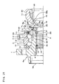
seal 37 before assembling the hub unit in the driving shaft member is fitted onto the driving shaft member with interference, and therefore the seal would not drop, the seal mount position would not move, and any such troubles would not occur during assembling. - FIGS. 3 to 5 show a second example of the embodiment of the present invention. In the case of this example, the
stop ring 35a provided between and engaged with theinside engagement groove 14 and theoutside engagement groove 13 is made by press punching a plate member made of a spring steel (including a tool steel such as SK5 or the like), in order to impart a spring property to thestop ring 35a. Such astop ring 35a is formed roughly in a C-shape overall, having a rectangular cross-section (a segment circle), and the entire ring is quench hardened. - In this example, a pair of
buffer members 52 composed of a resilient material such as rubber or a synthetic resin are bonded around the whole periphery on axially opposite side faces of thestop ring 35a. Hence, even if thehub 6a and thedrive shaft member 29 are relatively displaced in the axial direction, due to play existing in the coupling portion between both axially opposed faces of the inside and outsideengagement grooves stop ring 35a, direct bumping of the axially opposed faces of the inside and outsideengagement grooves stop ring 35a is prevented, thereby alleviating the shock on these faces. - As a result, durability of the inside and outside
engagement grooves stop ring 35a can be ensured, as well preventing the occurrence of any unpleasant metallic sound due to direct bumping of these portions. Moreover, by bonding theabovementioned buffer members 52 thereto, the effect of preventing wear of thestop ring 35a due to fretting can also be obtained. - The outer diameter of the
buffer member 52 bonded to the face, at least on the axially outside in the installed state (the left side face in FIGS. 3 and 4), of the opposite side faces of thestop ring 35a is made slightly smaller than that of thestop ring 35a. Specifically, as shown in FIG. 4, the outer diameter of thebuffer members 52 is made smaller so that when the tip end portion of thesplined shaft 30 is inserted into the inside of the splined bore 28, the outer peripheral edge of thebuffer member 52 bonded to the outside face of thestop ring 35a does not abut against theguide face 36 disposed on the inner end edge of thesplined bore 28. - This is because the frictional force acting on the abutting portion of the
guide face 36 and thebuffer member 52 would be larger than the frictional force acting on the abutting portion of theguide face 36 and thestop ring 35a. In other words, so that the larger frictional force is prevented from acting, thus making it easier to insert the tip portion of thesplined shaft 30 into the inside of thesplined bore 28. If the outer diameter of bothbuffer members 52 is restricted as described above, it is not necessary to worry about the direction of attaching thestop ring 35a to theinside engagement groove 14, thus facilitating installation. - In the case of this example, the axial dimension of the
splined shaft 30 and the splined bore 28 is restricted such that the tip end portion of thesplined shaft 30 protrudes slightly from the axially outer end edge of the splined bore 28, at the time of inserting thesplined shaft 30 into the splined bore 28, when the portion on the outer diameter side of thestop ring 35a attached to theinside engagement groove 14 enters into the outside engagement groove 13 (when thestop ring 35a is placed on engagement between the inside and outsideengagement grooves 14 and 13). Therefore, it can be easily judged whether or not thestop ring 35a is placed for engagement between the inside and outsideengagement grooves - In the case of this example, a bottomed
bore 53 is formed in the central portion of the tip end face of thesplined shaft 30, and anengagement groove 54 is formed around the whole periphery on the inner peripheral face of the middle part of the bottomed bore 53. - At the time of inserting the
splined shaft 30 into the splined bore 28, by engaging the tip portion of a drawing tool in theengagement groove 54, thesplined shaft 30 can be pulled from an opening on the axially outer end side of thesplined bore 28. - In addition, though not shown, the male spline formed on the outer peripheral face of the
splined shaft 30 is formed slightly twisted in the axial direction, to reduce any play in the circumferential direction of the splined engagement portion between thesplined shaft 30 and thesplined bore 28. Therefore, when thesplined shaft 30 is inserted into the splined bore 28, a large frictional force works in the axial direction between the outer peripheral face of thesplined shaft 30 and the inner peripheral face of thesplined bore 28. - In the case of this example however, since the
splined shaft 30 can be pulled out by the drawing tool whose tip portion is engaged in theengagement groove 54, the insertion of thesplined shaft 30 can be easily effected. - Moreover, in the case of this example, since the
attachment groove 54 for engaging the tip portion of the drawing tool therein is formed on the inner peripheral face of the bottomed bore 53 formed on the tip end face of thesplined shaft 30, the weight and the axial dimension of thedrive shaft member 29 is not increased, unlike the fourth example of the conventional construction. Though the strength of the tip portion of thesplined shaft 30 may be somewhat decreased with the formation of the bottomed bore 53, in practice there is no problem, since a large torque is not applied to the tip portion. - Furthermore, in the case of this example,
deep grooves 55 deeper than the female splined grooves formed on the inner peripheral face of the splined bore 28 are formed in the axial direction (in the right and left direction in FIG. 3, and in the direction out of the page in FIG. 5), as shown in FIG. 5, at a plurality of places in the circumferential direction of the splined bore 28, in a portion at least from the axially outer end edge of the splined bore 28 towards the axially outer end of the splined bore 28 which straddles theoutside engagement groove 13. - When the
splined shaft 30 is pulled out from the splined bore 28, the diameter of thestop ring 35a is reduced by a plurality of pins inserted from the axially outer end portion of the splined bore 28 into the respectivedeep grooves 55, to disengage thestop ring 35a from theoutside engagement groove 13. - In the example shown in the figure, the width of respective
deep grooves 55 is made narrow so that thesedeep grooves 55 do not affect the engagement state of the splined engagement portion between thesplined bore 28 and thesplined shaft 30. However, it is also possible to widen the width of respectivedeep grooves 55 so that the deep grooves span two to three splined grooves. - If the width of respective
deep grooves 55 is made wide, as described above, it is possible to form thesedeep grooves 55 by forging. In such a case, the number of gear teeth to be spline-engaged is reduced in the portion where thesedeep grooves 55 are formed, however thesedeep grooves 55 need be formed only in an axial part of the splined engagement portion. Therefore, the number of gear teeth to be spline-engaged is not reduced over the full length of the splined engagement portion. Hence, reduction of the torque which can be transmitted by the splined engagement portion is minimal, resulting in no practical problem. - In the case of this example, a
cap 34a for closing the opening at the axially outer end of the space where thesplined shaft 30 and the splined bore 28 exist is fixed to a portion facing close to the tip end face of thesplined shaft 30 in the axial middle part of the main body ofhub 6a. In the case of this example, thiscap 34a is generally made of a synthetic resin, and is formed in a bottomed cylindrical shape, having acylindrical portion 56 and adisk portion 57 for closing the opening at the axially outer end of thecylindrical portion 56. - When this
cap 34a is fitted to the middle part of thehub 6a, thecylindrical portion 56 is internally secured to the middle part of thehub 6a, with anengagement protrusion 58 formed around the whole periphery on the outer peripheral face of the axially inner end portion of thecylindrical portion 56 engaged in anengagement groove 59 formed around the whole periphery on the inner peripheral face of the middle part of thehub 6a. - Then, an outwardly
flanged collar 60 is formed on the outer peripheral face on the axially outer end side of thecylindrical portion 56 and abuts against a steppedface 61 formed on the inner peripheral face on the axially outer end side of thehub 6a. - Moreover, an O-
ring 63 is fitted into agroove 62 formed around the whole periphery of thecylindrical portion 56, to seal a space between the outer peripheral face of thecylindrical portion 56 and the inner peripheral face of the middle part of thehub 6a. - In the case of this example, as described above, by fixing the
cap 34a to a portion facing close to the tip end face of thesplined shaft 30, in the middle part of thehub 6a, the volume of the space between thecap 34a and theseal ring 37 where thesplined shaft 30 and the splined bore 28 exist can be reduced. Into this space, grease is filled to prevent rust and wear of thesplined shaft 30 and the splined bore 28 and to prevent the occurrence of abnormal sounds resulting from the rust and wear. - Moreover, by reducing the volume of the space as in this example, the amount of grease to be filled therein can be reduced to reduce the cost.
- In addition, the
cap 34a attached as described above can be easily removed from the middle part of thehub 6a by pulling on the inside face of thecollar 60 with the tip portion of a special tool inserted between the steppedface 61 and the axially inside face of thecollar 60. - Therefore, a chamfered
portion 64 is formed on the outer peripheral rim portion on the axially inside face of thecollar 60 to facilitate insertion of the tip portion of the special tool between the steppedface 61 and the axially inside face of thecollar 60. - Other construction and operation are substantially the same as for the case of the above described first example. Incidentally, the
coller 60 comprises larger and smaller diameter portions in a two-step shape, so that the tip end of the special tool can be securely inserted into the face on the axially inner side of thecoller 60. Then, the axially inside face of the smaller diameter portion is abutted to the steppedface 61 to provide a gap between the axially inside face of the larger diameter portion and the steppedface 61. - FIG. 6 shows a third example of the embodiment not being part of the present invention. In the case of this example, a
screw groove 65 which is an engagement groove, is formed on the inner peripheral face of a bottomedhole 53 provided in the central portion of the tip end face of thesplined shaft 30. When thesplined shaft 30 is inserted in the splined bore 28, an external thread formed at the tip portion of a pulling member is screwed in thescrew groove 65. - In the case of this example, the
hub 6a is made of a carbon steel material, for example, a carbon steel for mechanical structures such as S53C ∼ S55C (JIS G4051) or SAE 1060 ∼ SAE 1070. - Moreover, quenched hardened layers are formed by induction hardening or the like on portions on the peripheral face of the
hub 6a shown by the oblique hatching in FIG. 6 to improve the durability of these portions. The portions are continuous portions on the outer peripheral face in the middle part of thehub 6a from the base end portion of the axially inside face of themount flange 7 to the axially inner half of a steppedportion 33 in which theinner ring 50 is externally fitted, and on a portion on the inner peripheral face of thehub 6a where the splined bore 28 is formed. - Particularly, in the case of this example, since the quenched hardened layer is formed on a part of the splined bore 28, fretting wear due to the slight vibration in the axial direction of the splined bore 28 can be prevented, even if some chatter is produced in the axial direction in the engagement portion of the
splined shaft 30 and the splined bore 28, due to play existing in the engagement portion of the inside and outsideengagement grooves stop ring 35. Hence the durability of the splined engagement portion including the splined bore 28 can be sufficiently ensured. - Other construction and operation are substantially the same as for the case of the above described first and second examples.
- FIG. 7 shows a fourth example of the embodiment not being part of the present invention. In the case of this example, the outer peripheral face of the
outer ring 1 is formed in a simple cylindrical shape, and at the time of fitting theouter ring 1 into the suspension unit, it is internally secured in an attachment bore provided in the knuckle 40 (see FIGS. 37, 39 and 40). Moreover, a pair ofinner rings 50 provided withinner ring raceways 8 on the respective outer peripheral faces are externally fitted to the main body ofhub 6a and fixed by the crimpedportion 27, so that two rows ofinner ring raceways 8 are provided on the outer peripheral face of thehub 6a. - The end face of the crimped
portion 27 is made to abut against or positioned close to the axially outer end face of thehousing 11 of thedrive shaft member 29. An O-ring 42 is held in a retaininggroove 41 formed on the axially outer end face of thehousing 11 and made to resiliently abut against the end face of the crimpedportion 27 to seal a space between the crimpedportion 27 and thehousing 11. - In the case of this example, by abutting or positioning the end face of the crimped
portion 27 against or close to the axially outer end face of thehousing 11 of thedrive shaft member 29, thesplined shaft 30 is prevented from being displaced relative to the splined bore 28 further towards the left than as shown in FIG. 7. Together with this, in the case of this example, the outside engagement portion provided on the inner peripheral face of thehub 6a is a steppedportion 43 formed on the axially outer end edge portion of thesplined bore 28. - At the time of assembly of the drive wheel axle unit, this stepped
portion 43 is engaged with astop ring 35 which is engaged in aninside engagement groove 14 formed on the outer peripheral face of thesplined shaft 30, to thereby prevent thesplined shaft 30 from coming out from thesplined bore 28. - In the case of this example, the construction is such that the O-
ring 42 is subjected to preload with thedrive shaft member 29 fitted to thehub 6a. Hence, chatter in the axial direction between thesplined shaft 30 and the splined bore 28 can be prevented, thus preventing fretting wear due to slight vibration in the axial direction. - Incidentally, also in the present structure, as described in the first example of the embodiments, the modules of longitudinal elasticity of the seal material used is 200 [MPa] or less, desirably between 5 [MPa] and 60 [MPa], so that the seal member tightly comforts with the micro shape of this mating member in contact with it to obtain good seal performance. In addition, if the inner diameter of the O-
ring 42 is made smaller in size than the inner diameter of the retaininggroove 41, so that the O-ring 42 is fitted onto the inner diameter surface of the retaininggroove 41, the seal would not drop, the seal mount position would not move, and any such troubles would not occur during assembling. - When the driving shaf member slides in the axial direction during operation, the O-ring is deformed to always receive variable strain, and thus the use condition of O-ring is very severe. The variation amount of strain is determined by the maximum sliding resistance (several tens [kgf]) in the axial direction of th tripod joit mounted on the side of reduction gear of the driving shaft, the strain in the O-ring when receiving the load, and the deviation in size of the parts required for manufacturing. In order to make the strain in the O-ring small to improve its durability, it is desirable to use a tripod joint with small sliding resistance such that the axial sliding resistance at the normal joint angle from 5 degrees to 15 degrees is 20 [kgf] or less. When the compression strain can not be 30% or less, desirably 20 or less in spite that the strain in the O-ring is minimized as small as possible, the retaining
groove 41 formed on the outer end face of thehousing 11 is made to have a deeper depth, so that the outer end face comes directly into contact with the crimpedportion 27 of the hub when the compression strain of the O-ring exeeds 30% to avoid any further strain in the O-ring. Thus, by limiting the movement in either direction of the driving shaft member at the outer end face and at thestop ring 35 with a metal member shaped to have rigidity in the axial direction, the strain of the seal member is positively limited to a value or less. As a result, not only the improvement in durability of the seal member is obtained, but also the improvement in durability of the spline is obtained due to the reduction in vibration width of the sliding movement in the spline. - Incidentally, in the present structure where a preload is applied to the O-ring, since the O-ring is made of a soft material with a small modules of longitudinal elasticity, the splined engagement portion between the hub and the driving shaft member is constructed to allow relative sliding movements in the axial direction. Accordingly, the splined engagement portion must be lubricated because of the same reason as described in the first example of the embodiments.
- In the case of this example, a
cap 34 is fitted and fixed to the middle part of the main body ofhub 6a to face close to the end face of thesplined shaft 30, as in the case of the abovementioned second example, to thereby close off the middle part. Thecap 34 in this example however, is made of a metal plate, as with the first example and the third example described above. In the case of this example thus constituted, the volume of the space between thecap 34 and the O-ring 42 where thesplined shaft 30 and the splined bore 28 exist can be reduced to decrease the amount of grease to be filled in this space, and hence the cost can be reduced. - Other construction and operation are substantially the same as for the case of the above described first to third examples.
- FIG. 8 shows a fifth example of the embodiment not being part of the present invention. In the case of this example, a
metal backing member 69 with anencoder 44 is externally secured to the middle part of thedrive shaft member 29, at the axially outer end of thehousing 11, to make it possible to freely detect the rotation speed of thedrive shaft member 29. - This
metal backing member 69 is formed in an overall annular shape with an L-shape in cross-section, having acylindrical portion 45 and a ring-shapedportion 46, by bending a magnetic metal plate having corrosion resistance, for example a stainless steel plate such as SUS430. Such ametal backing member 69 is secured to thedrive shaft member 29 by externally fitting thecylindrical portion 45 to the axially outer end portion of thehousing 11 by an interference fit. The ring-shapedportion 46 is made to abut against the axially outer end face of thehousing 11. - Moreover, in the
cylindrical portion 45, there are formed a plurality of throughholes 47 of slit shape elongated in the axial direction (the right and left direction in FIG. 8), at equal intervals in the circumferential direction. Hence, the magnetic property of the outer peripheral face of thecylindrical portion 45 changes alternately at equal intervals in the circumferential direction. That is to say, in the case of this example, the outer peripheral face of thecylindrical portion 45 functions as theencoder 44. - A detection section of a
sensor 48 supported on a fixed portion such as the suspension unit or the like, is made to face close to theencoder 44, that is the outer peripheral face of thecylindrical portion 45, when fitted to the vehicle, to freely detect the rotation speed of thedrive shaft member 29 which rotates synchronously with the wheel. - An annular resilient plate (resilient material) 49 is attached to the axially outside face of the ring-shaped
portion 46 by bonding or baking and then clamped together with the ring-shapedportion 46, between the axially outer end face of thehousing 11 and the end face of the crimpedportion 27 provided in the inner axially end portion of thehub 6a, under resilient compression. Therefore, in the case of this example, thesplined shaft 30 is prevented from being displaced relative to the splined bore 28 further towards the left than as shown in FIG. 8, by means of the ring-shapedportion 46 and theresilient plate 49. Moreover, theresilient plate 49 seals the space between the axially outer end face of thehousing 11 and the end face of the crimpedportion 27. - Therefore, in the case of this example, not only are the
seal ring 37 described in the first to third examples and the O-ring 42 in the above described fourth example are not required, but also it is not necessary to subject each portion to a predetermined machining for attaching theseal ring 37 and O-ring 42 thereto. - The
resilient plate 49 is so formed that it does not protrude onto the outer peripheral face of thecylindrical portion 45, so that theencoder 44 disposed on the outer peripheral face of thecylindrical portion 45 and the detection section of thesensor 48 can be positioned sufficiently close to each other. - Other construction and operation are substantially the same as for the case of the above described first to fourth examples.
- Incidentally, the inner diameter of the
resilient plate 49 can be made smaller than the inner diameter of thecircular ring portion 46 of themetal ring 69, so that theresilient plate 49 has an radially inner portion which projects radially inward than the circular ring portion 46 (loward in Fig. 8). Then, the axially inside surface (the right side surface in fig. 8) of the radially inward portion of theresilient plate 49 is made flush with the axially inside surface of themetal ring 69, so that the projecting portion of theresilient plate 49 comes directly in contact with the axially outer end surface of thehousing portion 11. - In this structure, the
resilient plate 49 is held at the portion projecting radially inward than thecircular ring portion 46 between the axially inner end portion of thehub 6a and the axially outer end portion of thehousing portion 11, such that it is directly compressed. Accordingly, foreign matter such as rain water can be securely prevented at the contact portion between the axially outer end surface of thehousing portion 11 and theresilient plate 49 from entering the spline engagement portion through the fitting portion between thecylindrical portion 45 of themetal ring 69 and thehousing 11. - In addition, the axial deflection (resilient compression amount) of the
resilient plate 49 is designed for good sealing performance taking into consideration the size tolerance etc. of the parts required for production. For example, in the case of the axle unit for driving the automobile wheel, the minimum deflection is about 0.2 mm to about 0.6 mm, and the maximum deflection is about 1.3 mm to about 1.7 mm. - In operation, the thrust load based on the axial sliding resistance of the tripod joint used on the inboard side (the widthwise central side of the vehicle) is applied to the
resilient plate 49. Accordingly, the deflection amount of theresilient plate 49 at that time must be taken into consideration. In order to obtain enough durability for long term use, the compression deformation of the resilient plate must be designed to be kept 30 % or less (desirably 20 % or less) even under the expected maximum deflection amount. For such design, in the case of the axle unit for driving the automobile wheel, the thickness of theresilient plate 49 provided between the axially inner end portion of thehub 6a and themetal ring 69 must be about 4 mm to about 6 mm. Accordingly, the design with margin such as making the thickness about 6 mm to about 9 mm is desirable if there is no space problem. - If the contact condition of the
resilient plate 49 with the mating surface, subjected to large contact pressure, moves in sliding contact, the surface of theresilient plate 49 experiences premature fatigue. Accordingly, it is desirable on design that even if the torque applied to the constant velocity joint is opposite in direction, in other words even if it moves from the driving state to the inertia running state where engine braking occurs in the non-driven state, it is absorbed by the shear deflection of rubber of theresilient plate 49 and no sliding occurs in the circumferential direction at the contact portion between theresilient plate 49 and the axially inner end of thehub 6a. With the thickness (4 to 6 mm, and if space is available, 6 to 9 mm) as mentioned above, that design is possible. - The amount of deflection of the
resilient plate 49 always changes during operation of the axle unit for driving the vehicle wheel. In order to obtain the durability of theresilient plate 49 for long term use even under such extremely severe use conditions, theresilient plate 49 is desirable made of a thermoplastic polyether elastomer material such as Hytrel (Dupont) or Arnytel, which is a little more expensive than nitrile rubber. - FIG. 9 shows a sixth example of the embodiment not being part of the present invention. In the case of the above described fifth example, the
resilient plate 49a has a function to inhibit thesplined shaft 30 from being displaced relative to the splined bore 28 further towards the left than as shown in FIG. 8, and a function to seal the space between the ring-shapedportion 46 and the crimpedportion 27. - With these two functions, to make the function of preventing the displacement satisfactory, it is necessary to increase the rigidity of the
resilient plate 49a, while to make the sealing function satisfactory, it is necessary to decrease the rigidity of theresilient plate 49a to some extent. In the case of this example, in view of these circumstances, aflexible seal lip 51 which is relatively thin and has low rigidity is disposed on the outer peripheral edge portion of theresilient plate 49a. - Furthermore, the tip end edge of the
seal lip 51 is made to abut against the end face of the crimpedportion 27 around the whole periphery to seal the space between the ring-shapedportion 46 and the crimpedportion 27. On the other hand, the main body of theresilient plate 49a has a higher rigidity so that it can effectively inhibit thesplined shaft 30 from being displaced relative to the splined bore 28 further towards the left than as shown in FIG. 8. - FIGS. 10 and 11 show a seventh example of the embodiment not being part of the present invention. In the case of this example, a
metal backing member 69a externally secured to the axially outer end portion of thehousing 11 is made by subjecting a plate material made of a spring steel (including a tool steel such as SK5 or the like) to pressing and bending, and then entirely to quench hardening. - In the case of this example, by forming an
inclined portion 66 with the inclination increasing axially outward towards the inner diameter side, on a portion of the inner diameter side of a ring-shapedportion 46 of themetal backing member 69a, the portion on the inner diameter side of the ring-shapedportion 46 is protruded axially outward. - Moreover, as shown in FIG. 11, a plurality of
notches 67 are formed on the inner peripheral rim portion on the inner diameter side of the ring-shapedportion 46 at equal intervals in the circumferential direction, to form a plurality oftongues 90 in the mid portions between thesenotches 67, thereby enough resilience is imparted to the portion on the inner diameter side of the ring-shapedportion 46 including theinclined portion 66. - The tip portion on the inner diameter side of the ring-shaped
portion 46 formed as described above, that is, the tip portion of thetongues 90 is made to abut resiliently against the end face of the crimpedportion 27, thereby inhibiting thesplined shaft 30 from being displaced relative to the splined bore 28 further towards the left than as shown in FIG. 10. - Hence, chatter in the axial direction between the
splined shaft 30 and the splined bore 28 is prevented. In this state, a preload loading equivalent to or greater than an axial sliding resistance (several tens of kgf) of a tripod type constant velocity joint, not-shown, incorporated in a section of the transmission (right side in FIG. 10), not shown, is applied to thetongues 90. - Hence, at the time of driving, even when a load in a direction of thrust (the right and left direction in FIG. 10) is applied to the constant velocity joint, the engagement portion between the
splined shaft 30 and the splined bore 28 does not slide axially, thus preventing wear from being caused in the engagement portion. - These
tongues 90 are designed so that even when an excess load is applied to therespective tongues 90 at the time of assembly, for example, even when thetongues 90 are clamped between thehub 6a and thedrive shaft member 29 and bent until they become flat, the stress generated inside thetongues 90 will not exceed the allowable stress, thus resulting in no damage in thetongues 90. That is to say, since the stress generated inside thetongues 90 increases with the increase of the displacement amount of thetongues 90 when they are bent until they become flat, the dimensions of each portion are decided to keep to a value from 2 to 3 mm the displacement amount of thetongues 90 when bent to become flat. - A
seal lip 68 is formed in an overall cylindrical shape from a resilient material such as a rubber like elastomer, and its axially inner end is securely connected by bonding or by baking to the axially outside face of the ring-shapedportion 46. In addition, an axially outer end rim or tip end edge of theseal lip 68 is made to abut resiliently against the axially inner end face of theinner ring 50 around the whole periphery to seal the space between the axially outer end face of thehousing 11 and the end face of the crimpedportion 27. - In the case of this example, a portion towards the tip of the
seal lip 68 is formed in a curved shape to impart a suitable resilience to this portion, so that the position of abutment and the abutment pressure of the axially outer end rim of theseal lip 68 are not changed with respect to the axially inner end face of theinner ring 50, at the time of operating the rolling bearing unit for wheel, even if thesplined shaft 30 is displaced relative to the splined bore 28 further towards the left than as shown in FIG. 10 against the resilience of the inner diameter side portion of the ring-shapedportion 46. - Other construction and operation are substantially the same as for the case of the above described fourth and fifth examples shown in FIGS. 7 and 8.
- FIG. 12 shows an eighth example of the embodiment not being part of the present invention. In the case of this example, the through holes (FIG. 10) are not formed in the
cylindrical portion 45 of ametal backing member 69b externally secured on the axially outer end portion of thehousing 11. - Moreover, in this case, notches 67 (FIGS. 10 and 11) are not formed on the inner peripheral rim on the inner diameter side of the ring-shaped
portion 46 of themetal backing member 69b, the inner diameter side portion of the ring-shapedportion 46 being instead aflat spring portion 91 in a form of diaphragm. - Furthermore in this case, a covering
portion 70 is formed in a cylindrical shape by a part of a resilient material constituting theseal lip 68 and disposed in the portion on the outer diameter side of theseal lip 68 connected to the axially outside face of the ring-shapedportion 46. - The tip end edge of the covering
portion 70 is extended up to the outer diameter side of a reduced diameter steppedportion 71 formed on the inner end portion of theinner ring 50 around the whole periphery, thereby covering the portion sealed by theseal lip 68. - In the case of this example, therefore, foreign matter such as rain water or the like is prevented from directly touching the
seal lip 68, thereby making the sealing function of theseal lip 68 satisfactory. - Furthermore, in the case of this example, a part of the resilient material constituting the
seal lip 68 is bonded to the axially outside face of theflat spring portion 91 formed on the inner diameter side of the ring-shapedportion 46, so that the axially outside face of theflat spring portion 91 does not abut directly against the end face of the crimpedportion 27. The reason for this is to prevent fretting wear from occurring in an abutting portion between the axially outside face of theflat spring portion 91 and the end face of the crimpedportion 27. - In the case of this example, an outwardly
flanged collar 72 is formed on the axially inner end rim of thecylindrical portion 45 of themetal backing member 69b. When themetal backing member 69b is pressed onto the axially outer end portion of thehousing 11, the tip portion of a press jig is made to abut against the outside face of thecollar 72, without crushing theseal lip 68. - Other construction and operation are substantially the same as for the case of the above described seventh example.
- FIG. 13 shows a ninth example not being part of the embodiment of the present invention. In the case of this example, by forming a stepped portion 73 on an inner peripheral rim portion of the ring-shaped
portion 46 of ametal backing member 69c supported on the axially outer end of thehousing 11, then by a part of the axially outside face on the inner diameter side portion of the ring-shapedportion 46, a portion for connecting theseal lip 68 to the bottom edge of the coveringportion 70, is urged close to the axially inner end face of theinner ring 50. The amount of the resilient material for theseal lip 68 and the coveringportion 70 is thus reduced by the amount by which the part of the axially outside face of the ring-shapedportion 46 is made closer to the axially inner end face of theinner ring 50, thereby reducing the cost of theseal lip 68 and the coveringportion 70. - Other construction and operation are substantially the same as for the case of the above described eighth example.
- FIG. 14 shows a tenth example of the embodiment not being part of the present invention. In the case of this example, a
cylindrical portion 45 of ametal backing member 69d for supporting a seal lip 68a is externally secured to the reduced diameter steppedportion 71 formed on the axially inner end portion of theinner ring 50. - In addition, an axially inside face of a
flat spring portion 91 of themetal backing member 69d is made to abut resiliently against the axially outer end face of thehousing 11 via a part of the resilient material constituting the seal lip 68a. The tip edge of the seal lip 68a is also made to abut against a conical inclined face on the axially outer end side in the outer peripheral face of thehousing 11 around the whole periphery. - In the case of this example, the size of diameter of the tip end edge of the seal lip 68a in a free state is made slightly larger than that of the outer end face of the
housing 11. The reason for this is to prevent the seal lip 68a from being turned over due to bumping of the tip edge of the seal lip 68a against the outer end face of thehousing 11, when thesplined shaft 30 is inserted into thesplined bore 28. - The reduced diameter stepped
portion 71 formed on the axially inner end portion of theinner ring 50, being the portion where thecylindrical portion 45 of themetal backing member 69d is externally secured, may be deformed slightly when the axially inner end face of theinner ring 50 is attached to the axially inner end portion of thehub 6a by crimping. - In the case of this example, therefore, a
resilient material 74 such as rubber is bonded around the whole periphery on the inner peripheral face of thecylindrical portion 45 to make the fit strength of thecylindrical portion 45 with respect to the reduced diameter steppedportion 71 sufficient and to ensure the sealing performance in the fitted portion, even if the reduced diameter steppedportion 71 is deformed to change the diameter or the like of the reduced diameter steppedportion 71. - Other construction and operation are substantially the same as for the case of the above described ninth example.
- FIG. 15 shows an eleventh example not being part of the embodiment of the present invention. In the case of this example, the base end edge of a
seal lip 68b is bonded to the inner peripheral rim portion of aflat spring portion 91 which constitutes ametal backing member 69d. Moreover, the tip edge of theseal lip 68b is made to abut resiliently against a curved face existing in a connecting portion between the outer peripheral face of thesplined shaft 30 and the axially outer end face of thehousing 11. - Furthermore, the base edge of a covering
portion 70a is connected to the axially inside face of aninclined portion 66 disposed on the inner diameter side portion of the ring-shapedportion 46, and the tip end edge of the coveringportion 70a is extended towards the outer diameter side of the axially outer end portion of thehousing 11, thereby covering the portion sealed by theseal lip 68b around the whole periphery. - In addition, in the case of this example, the thickness of the resilient material which exists between the
seal lip 68b and the coveringportion 70a is made large, and the axially inside face of the resilient material abuts against the axially outer end face of thehousing 11, the portion where the thickness is made large being designated as aresilient plate portion 75. In this case, by providing such aresilient plate portion 75, the function to inhibit thesplined shaft 30 from being displaced relative to the splined bore 28 further towards the left than as shown in FIG. 15 is made satisfactory. - Other construction and operation are substantially the same as for the case of the above described tenth example.
- FIG. 16 shows a twelfth example not being part of the embodiment of the present invention. In the case of this example, an
encoder 76 constitutes a rotation speed detection unit mating with thesensor 48 and is supported and secured on the axially inside face of aseal ring 19a for closing an opening of the axial inner end of a space in which is disposed a plurality of rollingmembers 12. - That is to say, in the case of this example, a combined seal ring is adopted as the
seal ring 19a, with theencoder 76 bonded and secured to the axially inside face of aslinger 77 of the combined seal ring. The combined seal ring is externally secured to the axially inner end portion of theinner ring 50. Theencoder 76 is formed in an overall ring shape from a permanent magnet such as a rubber magnet in which ferrite powder is incorporated, and magnetized in the axial direction (in the right and left direction in FIG. 16). The magnetized direction is changed alternately in the circumferential direction at equal intervals. - Therefore, on the axially inside face of the
encoder 76, south and north poles are arranged alternately at equal intervals. Also in the case of this example, the detection section of thesensor 48 supported on a fixed portion, such as the suspension unit or the like is made to face close to the axially inside face of theencoder 76 when fitted to the vehicle, to freely detect the rotation speed of thedrive shaft member 29 which rotates synchronously with the wheel. - In the case of this example, a
seal lip 68c connected to ametal backing member 69e externally secured to the axially outer end portion of thehousing 11, is formed in an overall annular shape with an approximate U-shape cross-section, and comprises a pair of ring-shapedportions portion 79 for making the inner peripheral rims of the ring-shapedportions portion 80 which is bent axially outward from the outer peripheral rim of the outside ring-shapedportion 78a of the ring-shapedportions - With such a
seal lip 68c, a portion on the outer periphery side in the inside ring-shapedportion 78b is securely connected by bonding or baking to a portion on the inner periphery side on the axially outside face of the ring-shapedportion 46 of themetal backing member 69e and to the inner peripheral rim portion of the ring-shapedportion 46. - Moreover, the tip end edge of the protruding
portion 80 is made to abut resiliently against the end face of the crimpedportion 27 around the whole periphery. - Furthermore, in this condition, a part of the axially inside face of the axially inside ring-shaped
portion 78b is made to abut resiliently against the axially outer end face of thehousing 11 around the whole periphery, to seal the fitted and secured portion between themetal backing member 69e and the axially outer end portion of thehousing 11. The axial size (in the right and left direction of FIG. 16) of theseal lip 68c in a free state is made sufficiently larger than the axial space between the axially outer end face of thehousing 11 and the end face of the crimpedportion 27. - In the case of this example constructed as described above, since the
seal lip 68c is formed in an approximate U-shape in cross-section, the tip edge of the protrudingportion 80 formed on the outer peripheral rim of the axially outside ring-shapedportion 78a can be displaced by a large amount in the axial direction. Therefore, even if the axial interval between the axially outer end face of thehousing 11 and the end face of the crimpedportion 27 is changed significantly (for example, by about 1 mm) due to the play existing in the coupling portion between the inside and outsideengagement grooves stop ring 35, the tip end edge of the protrudingportion 80 can follow the change, thus sufficiently ensuring an abutting pressure of the tip end edge of the protrudingportion 80 against the end face of the crimpedportion 27. - Since the
seal lip 68c is formed in an approximate U-shape in cross-section, the resistance to deformation of the middle part of theseal lip 68c can be made smaller than any frictional resistance acting on the abutting portion between the tip edge of the protrudingportion 80 and the end face of the crimpedportion 27, thus ensuring that the abutting portion does not slide during operation. Accordingly, the sealing performance of theseal lip 68c can be stabilized. - In the case of this example, when the
cylindrical portion 45 of themetal backing member 69e is pressed onto the axially outer end portion of thehousing 11, a jig is pressed against a portion on the outer diameter side where the ring-shapedportion 78b of theseal lip 68c is not bonded, of the axially outside face of the ring-shapedportion 46 of themetal backing member 69e. - In other words, to ensure a portion for pressing the jig on the portion on the outer diameter side of the axially outside face of the ring-shaped
portion 46, the size of the outer diameter of the ring-shapedportion 46 is made sufficiently larger than that of the axially inside ring-shapedportion 78b of theseal lip 68c. - Other construction and operation are substantially the same as for the case of the above described first and third examples.
- FIG. 17 shows a thirteenth example not being part of the embodiment of the present invention. In the case of this example, the tip edge of a protruding
portion 80 constituting aseal lip 68c is made to abut against the axially inner end face of theinner ring 50 around the whole periphery. With this example therefore, the tip edge of the protrudingportion 80 is made to abut against the axially inner end face of theinner ring 50 having a higher positional accuracy and shape accuracy after being fitted than that of the end face of the crimpedportion 27. Hence the sealing performance of theseal lip 68c is further stabilized. - In the case of this example, a
collar 72 for pressing by a press jig is formed on the axially inner end rim of thecylindrical portion 45 of ametal backing member 69f externally secured to the axially outer end portion of thehousing 11. - Accordingly, in the case of this example there is no larger allowance for a press portion for the press jig as in the above described twelfth example, on the outer diameter side of the axially outside face of the ring-shaped
portion 46 of themetal backing member 69f. - Other construction and operation are substantially the same as for the case of the above described twelfth example.
- FIG. 18 shows a fourteenth example not being part of the embodiment of the present invention. In the case of this example, a
metal backing member 69g for supporting aseal lip 68d is formed in the shape of a crank in cross-section, and thecylindrical portion 45 provided on the outermost diameter side is externally secured to the reduced diameter steppedportion 71 formed on the axially inner end portion of theinner ring 50. The reason why thecylindrical portion 45 is externally secured to the reduced diameter steppedportion 71 is to keep thecylindrical portion 45 from interfering with the tip portion of thesensor 48. - On the other hand, the
seal lip 68d supported by themetal backing member 69g has a portion on the outer diameter side of an axially outside ring-shapedportion 78a connected to an inner peripheral edge portion of themetal backing member 69g, and makes the tip edge of a protrudingportion 80 provided on an outer peripheral rim of an axially inside ring-shapedportion 78b abut against the axially outer end face of thehousing 11 around the whole periphery. - In the case of this example, a part of the resilient material constituting the
seal lip 68d is bonded to the inner peripheral face of thecylindrical portion 45. Therefore, even if the reduced diameter steppedportion 71 is deformed when the crimpedportion 27 is formed, the fit strength of thecylindrical portion 45 to the reduced diameter steppedportion 71 can be made suitable, and the sealing performance of the fitting portion of thecylindrical portion 45 can be ensured. - Other construction and operation are substantially the same as for the case of the above described twelfth example.
- FIGS. 19 and 20 show a fifteenth example of the embodiment not being part of the present invention. In the case of this example, a seal member or seal
lip 68e is supported on ametal backing member 69e externally secured to the axially outer end portion of thehousing 11 and formed in an approximate cylindrical shape overall, and in a kink-shape in cross-section. The axially inner end portion or base end of theseal lip 68e is bonded to the outer peripheral face of acylindrical portion 45 and the outer peripheral rim portion of a ring-shapedportion 46 of themetal backing member 69e. - Moreover, an anchoring
protrusion 81 is formed on an inner peripheral face of a tip portion around the whole periphery and engaged in an anchoringgroove 82 formed in the reduced diameter steppedportion 71 of theinner ring 50 around the whole periphery. The height of the anchoringprotrusion 81 is made larger than the depth of the anchoringgroove 82. - Moreover, the diameter of the inner peripheral rim of the anchoring
protrusion 81 in a free state is made smaller than that of the bottom face of the anchoringgroove 82. Therefore, with the anchoringprotrusion 81 is engaged in the anchoringgroove 82, the inner peripheral rim of the anchoringprotrusion 81 abuts resiliently against the bottom face of the anchoringgroove 82 around the whole periphery. In other words, the tip portion of theseal lip 68e is externally fitted to the bottom face of the anchoringgroove 82. In this condition, the space between thehub 6a and thedrive shaft member 29 is sealed. - When engaging the anchoring
protrusion 81 in the anchoringgroove 82, thesplined shaft 30 is inserted into the splined bore 28 from the right to the left in FIG. 19, with themetal backing member 69e externally secured on the axially outer end portion of thehousing 11. By this insertion operation, the anchoringprotrusion 81 formed on the tip portion of theseal lip 68e is resiliently widened in the inner diameter, while being guided over a the chamferedportion 83 formed in a conical convex shape and provided on the axially inner end rim of the reduced diameter steppedportion 71. Then, after following over the outer peripheral face of the reduced diameter steppedportion 71, the inner diameter is again reduced to enter into the anchoringgroove 82. - In the case of this example constructed as described above, even if the
housing 11 and the anchoringgroove 82 formed on the outer peripheral face of the reduced diameter steppedportion 71 are axially displaced relative to each other due to the play existing between the engagement portion of the inside and outsideengagement grooves stop ring 35, akinked portion 84 formed in the middle part of theseal lip 68e bends, thereby allowing the anchoringprotrusion 81 formed on the tip portion of theseal lip 68e to follow the anchoringgroove 82. - Hence, sliding is not caused in the abutting portion between the inner peripheral rim of the anchoring
protrusion 81 and the bottom face of the anchoringgroove 82, and deterioration of the sealing performance due to wear or the like can be prevented. - In the case of this example, the size of the inner diameter of the ring-shaped
portion 46 of themetal backing member 69e is made sufficiently smaller than that of the anchoringprotrusion 81 provided at the tip portion of theseal lip 68e in a free state. Hence, when themetal backing member 69e is pressed onto and secured to the outer end portion of thehousing 11, the tip portion of theseal lip 68e does not interfere with the press jig which is made to abut against the axially outside face of the ring-shapedportion 46 of themetal backing member 69e. Other construction and operation are substantially the same as for the case of the above described twelfth example. - FIG. 21 shows a sixteenth example not being part of the embodiment of the present invention. In the case of this example, the
inner ring 50 is held on the axially inner end portion of thehub 6a by astop ring 85 engaged in the axially inner end portion of thehub 6a. That is to say, an anchoringgroove 86 is formed on the outer peripheral face of the axially inner end portion of thehub 6a around the whole periphery, and thestop ring 85 is engaged in the anchoringgroove 86. Thestop ring 85 is composed of a pair of stop ring elements, each being semicircular. Such astop ring 85 is forced to press theinner ring 50 against thehub 6a axially outward to impart a suitable preload to the rollingmembers 12, while engaging the inner peripheral rim portion thereof in the anchoringgroove 86. - Furthermore, as the
stop ring 85, one is selected having a suitable thickness to keep a sufficient preload on the rollingmembers 12, even when the above-mentioned force pressing theinner ring 50 axially outward is released. - Other construction and operation are substantially the same as for the case of the above described fifteenth example.
- FIG. 22 shows a seventeenth example not being part of the embodiment of the present invention. In the case of this example, a
metal backing member 69h for supporting aseal lip 68f is supported and secured to the axially inner end portion of thehub 6a. A part of themetal backing member 69h is disposed on the circumference of thestop ring 85 for holding the inner-ring 50 on the axially inner end portion of thehub 6a. Hence, in the case of this example, the pair of stop ring elements constituting thestop ring 85 are prevented from being displaced radially outward and thus inadvertently coming out from the anchoringgroove 86 formed towards the axially inner end on the outer peripheral face of thehub 6a. - That is to say, the
metal backing member 69h is formed in an overall circular shape and in the shape of a crank in cross-section, and comprises a small diametercylindrical portion 87 for externally securing to the axially inner end portion of thehub 6a, a ring-shapedportion 88 bent a radially outward from the axially outer end rim of the small diametercylindrical portion 87, and a large diametercylindrical portion 89 bent axially outward from the outer peripheral rim of the ring-shapedportion 88. - The axially outside face of the ring-shaped
portion 88 is made to abut against or face close to the axially inside face of thestop ring 85, while the inner peripheral face of the large diametercylindrical portion 89 is made to abut against or face close to the outer peripheral face of thestop ring 85. - The axially outer end or base end of the
seal lip 68f is connected to the outer peripheral face of thecylindrical portion 89 with a larger diameter and the outer peripheral rim portion of the ring-shapedportion 88, while the inner peripheral rim of an anchoringprotrusion 81 disposed on the inner peripheral face of the axially inner end or tip end of theseal lip 68f is made to abut against the bottom face of an anchoringgroove 82a formed on the outer peripheral face of the axially outer end portion of thehousing 11 around the whole periphery. - In the case of this example also, a chamfered
portion 83a is formed on the axially outer end rim portion of thehousing 11, which serves as a guide face when the anchoringprotrusion 81 disposed at the tip portion of theseal lip 68f is engaged in the anchoringgroove 82a. - Other construction and operation are substantially the same as for the case of the above described sixteenth example.
- FIG. 23 shows an eighteenth example not being part of the embodiment of the present invention. In the case of this example, the
hub 6e comprises a hubmain body 102, a pair ofinner rings 50 and anut 103. That is to say, thehub 6e is constituted by screwing and fastening thenut 103 on an external thread formed on the axially inner end portion of the hubmain body 102, with the pair ofinner rings 50 externally fitted to the hubmain body 102. - In addition, a
washer 104 is positioned between thenut 103 and the insideinner ring 50. Anouter ring 1 is internally fitted to the inside of asupport bore 105 formed in aknuckle 40, and held between acollar 106 formed on the inner peripheral face of an opening on one end of the support bore 105 and astop ring 107 engaged with the inner peripheral face of the other end of the support bore 105, from axially opposite sides. - Other construction and operation are substantially the same as for the case of the above described fourth example shown in FIG. 7. Here, with the pair of
inner rings 50, the axially outsideinner ring 50 may be formed integrally with the hubmain body 102. - FIGS. 24 and 25 show a nineteenth example not being part of the embodiment of the present invention. In the case of this example, the inside engagement portion or inside
engagement groove 14 is formed on the outer peripheral face of the middle part on the outer end side of thesplined shaft 30 around the whole periphery. Moreover, an outside engagement portion or steppedportion 108 is formed on the circumference of the opening on the axially outer end of the splined bore 28 formed in the central portion of thehub 6a, at a position coordinated with theinside engagement groove 14, around the whole periphery. Anannular stop ring 109, a part of which is shown in FIG. 25, is fitted between theinside engagement groove 14 and the steppedportion 108, so as to span therebetween. - The
stop ring 109 is formed in an overall annular shape from a resilient metal plate, for example, a spring steel such as SK5, a stainless spring steel or the like, so that the thickness thereof can be resiliently contracted freely in the axial direction (the right and left direction in FIG. 24). More specifically, thestop ring 109 is provided with a ring-shapedportion 110 around the whole periphery on the outer peripheral side, and a plurality ofresilient tongues 111 formed on the inner peripheral rim portion of the ring-shapedportion 110 protruding radially inward and in the axial direction. - The diameter of the inscribing circle at the tip edge (end edge on the inner peripheral side) of the plurality of
resilient tongues 111 which constitute thestop ring 109 is made smaller than the diameter of the circumscribing circle of thesplined shaft 30, in a free state of thestop ring 109. - The
stop ring 109 is externally fitted to the axially outer end portion of thesplined shaft 30, with the tip portion (end portion on the inner peripheral side) of the plurality ofresilient tongues 111 resiliently deformed in a radially outward direction of thestop ring 109. - The tip end portion of the
resilient tongues 111 are then resiliently restored radially inward, so that the plurality ofresilient tongues 111 fit into theinside engagement groove 14, with the tip end portion of theresilient tongues 111 and theinside engagement groove 14 engaged with each other. In this state, the ring-shapedportion 110 is made to abut against the steppedportion 108. - It is a matter of course in this case, the diameter of the groove bottom of the
inside engagement groove 14 is restricted (the diameter of the groove bottom of theinside engagement groove 14 is made smaller than the diameter of the groove bottom of the male splines) and the width of the tip portion of theresilient tongues 111 is also restricted (the width is made larger than the width of the splined grooves), so that theresilient tongues 111 cannot come away from theinside engagement groove 14 along the splined grooves formed on the outer peripheral face of thesplined shaft 30. The ring-shapedportion 110 may be formed in a segment circle, to make it easy to perform the work of engaging the respectiveresilient tongues 111 with theinside engagement groove 14. - Alternatively, the spline grooves may be left off the tip portion of the
splined shaft 30, on the tip end side of theinside engagement groove 14 with which thestop ring 109 is engaged, so that thesplined shaft 30 has a cylindrical face with a smaller diameter than that of the groove bottom of the splined grooves. In this case, the diameter of the bottom portion of theinside engagement groove 14 will be smaller than the outer diameter of the cylindrical face. - Incidentally, in the present case, the
stop ring 109 is mounted after thesplined shaft 30 is inserted into thesplined hole 28. - As in the first example shown in Fig. 1, it is impossible to insert the
splined shaft 30 into thesplined hole 28 in the state where thestop ring 35 is previously installed in thesplined shaft 30. - Furthermore, a
seal member 112 comprising ametal backing member 69i and aresilient plate 49, is disposed between the axially outer end face of thehousing 11 provided on the axially inner end portion of thedrive shaft member 29 provided with thesplined shaft 30, and the axially inner end face of thehub 6a. - The
metal backing member 69i of theseal member 112 is made by forming a metal plate, for example, a carbon steel plate such as SPCC in an overall annular shape with an L-shape in cross-section, and is secured on the axially outer end portion of thehousing 11. Specifically, thecylindrical portion 45 formed on the outer peripheral rim portion of themetal backing member 69i is externally fitted onto the axially outer end portion of thehousing 11 by an interference fit. - The
resilient plate 49 made by forming an elastomer such as rubber, vinyl or the like in a ring form, is attached to the axially outside face of the ring-shapedportion 46 of themetal backing member 69i around the whole periphery by baking or bonding. - Such a
resilient plate 49 of theseal member 112 is resiliently clamped between the axially outer end face of thehousing 11 and the crimpedportion 27 existing on the axially inner end face of thehub 6a, with thestop ring 109 spanning between theinside engagement groove 14 and the steppedportion 108. - The resilient force for clamping the
resilient plate 49 therebetween based on the resilience of thestop ring 109 is set to be slightly larger than the thrust load applied to thesplined shaft 30 at the time of driving, for example, around 100 kgf. With the axle unit for supporting the wheel of this example, theresilient plate 49 is resiliently clamped between the axially outer end face of thehousing 11 and the crimpedportion 27 by spanning thestop ring 109 between theinside engagement groove 14 and the steppedportion 108 in an axially compressed state, thereby positioning thehub 6a and thedrive shaft member 29 in the axial direction. - In the case of the axle unit for driving the wheel of this example constructed as described above, the
stop ring 109 has resilience in the axial direction, and theresilient plate 49 is resiliently clamped between the crimpedportion 27 existing on the axially inner end face of thehub 6a and the axially outer end face of thehousing 11, with thestop ring 109 spanning between theinside engagement groove 14 and the steppedportion 108. Therefore, regardless of vibration caused during driving, abnormal sounds due to bumping between the members do not occur. Moreover, while driving an automobile, the thrust load produced in the section of the tripod type constant velocity joint (not shown) provided on the differential gear side, is applied to thedrive shaft member 29 via a drive shaft (not shown). - Since the direction of the thrust load changes depending upon the operational state of the tripod type constant velocity joint, a force in a direction to pull out the
drive shaft member 29 from thehub 6a is applied in certain instances. - However, even in this case, since the force clamping the
resilient plate 49 based on the resilience of thestop ring 109 is set to be larger than the thrust load applied to thesplined shaft 30 with the tripod type constant velocity joint being driven, for example, around 100 kgf, then thedrive shaft member 29 and thehub 6a will not be displaced axially. Accordingly, the crimpedportion 27 and theresilient plate 49 are not separated, and the sealing performance between thedrive shaft member 29 and thehub 6a by means of theresilient plate 49 can be ensured, regardless of the thrust load applied during driving. - FIGS. 26 and 27 show a twentieth example not being part of the embodiment of the present invention. In the case of this example, as a
stop ring 109a spanning between theinside engagement groove 14 on the outer peripheral face of thesplined shaft 30 of thedrive shaft member 29 and the steppedportion 108 on the inner peripheral face of thehub 6a, a corrugated plate spring in the shape of segment circle is used. - The
stop ring 109a formed from a similar resilient metal plate as thestop ring 109 used in the nineteenth example described above is spanned between theinside engagement groove 14 and the steppedportion 108, with the inner diameter thereof resiliently expanded. - Other construction and operation are substantially the same as for the case of the above described nineteenth example, hence similar components are denoted by the same symbols, and repeated description is omitted.
- FIG. 28 shows a twenty-first example not being part of the embodiment of the present invention. In the case of this example, at the tip portion of the
splined shaft 30 of thedrive shaft member 29, acylindrical portion 113 is formed. The outer diameter of thecylindrical portion 113 is smaller than the diameter of the inscribing circle of the groove bottom of the splined groove formed on thesplined shaft 30. The inside engagement portion or insideengagement groove 14 is formed in the axially middle part of thecylindrical portion 113 around the whole periphery. - Moreover, an outside engagement portion or stepped
portion 108 is formed on the circumference of the axially outer end opening of the splined bore 28, at a position coordinated withinside engagement groove 14, around the whole periphery. - A
stop ring 15d in the shape of a segment circle and acircular spacer 114 are fitted between theinside engagement groove 14 and the steppedportion 108, spanning between theinside engagement groove 14 and the steppedportion 108. - The above described
stop ring 15d is a resilient metal plate, for example, a spring steel such as SK5 or a stainless spring steel, and is formed in the shape of segment circle overall so that the diameter can be resiliently expanded and contracted freely. The inner diameter of thestop ring 15d in a free state is smaller than the outer diameter of thecylindrical portion 113. Moreover, the inner diameter of thespacer 114 is slightly larger than the outer diameter of thecylindrical portion 113, and the outer diameter of thespacer 114 is sufficiently larger than the inner diameter of thesplined bore 30. - Furthermore, a
seal member 112 comprising ametal backing member 69i and aresilient plate 49 is disposed between the axially outer end face of thehousing 11 and the axially inner end face of thehub 6a, in a similar manner to in the nineteenth example shown in FIGS. 24 and 25. Theresilient plate 49 constituting theseal member 112 is clamped in a resiliently compressed (preload applied) state between the axially outer end face of thehousing 11 and the inner end face of thehub 6a, with thestop ring 15d and thespacer washer 114 spanning between theinside engagement groove 14 and the steppedportion 108. - With the drive wheel axle unit of this example, the
resilient plate 49 is resiliently clamped between the axially outer end face of thehousing 11 and the crimpedportion 27 by spanning thestop ring 15d together with thespacer washer 114 between theinside engagement groove 14 and the steppedportion 108 in an axially compressed state, thereby positioning thehub 6a and thedrive shaft member 29 in the axial direction. - In the case of the axle unit of this example constructed as described above, since the
spacer 114 is disposed between thestop ring 15d and the steppedportion 108, thesestop ring 15d and the steppedportion 108 are prevented from abutting against each other over a small area. As a result, fretting wear can be prevented from occurring on thestop ring 15d and the steppedportion 108, irrespective of the thrust load applied between thedrive shaft member 29 and thehub 6a at the time of driving. - That is to say, the
stop ring 15d cannot be made wide radially because it must be resiliently enlarged diametrically at the time of engaging in theinside engagement groove 14, thus restricting the outer diameter of thestop ring 15d. - Moreover, the diameter of the opening peripheral edge of the splined bore 28 is somewhat large, due to a chamfered portion existing in the opening. Therefore, when only the
stop ring 15d is provided between theinside engagement groove 14 and the steppedportion 108, the abutment area between the steppedportion 108 and thestop ring 15d is narrow, and hence the surface pressure on the abutting portion becomes high so that fretting wear easily occurs at the abutting portion. - On the contrary, in the case of the drive wheel axle unit of this example, by providing the
spacer 114 and thus ensuring a suitable abutment area between the opposite faces of thespacer 114 and the steppedportion 108 and thestop ring 15d, the surface pressure on the abutting portion can be reduced, and fretting wear can thus be prevented from occurring at the abutting portion. In addition, the resilience force (preload) applied to theresilient plate 49 is preferably set to be slightly larger than the thrust load applied to thesplined shaft 30 at the time of driving, for example, about 100 kgf, due to the reason as in the nineteenth example as shown in Figs. 24 and 25, and as in the twentieth example as shown in Figs. 26 and 27. - Other construction and operation are substantially the same as for the case of the above described nineteenth and twentieth examples.
- FIG. 29 shows a twenty-second example not being part of the embodiment of the present invention. In the case of this example, a
resilient ring 115 made of an elastomer such as rubber, vinyl or the like is clamped between thespacer 114 and the steppedportion 108 with theresilient ring 115 resiliently compressed between thespacer 114 and the steppedportion 108. - In the example shown in FIG. 29, the
resilient ring 115 is plated or bonded to the inside face of thespacer 114, so that theresilient ring 115 can be handled integrally with thespacer 114. In such a case, the cap 34 (FIG. 28) fitted to thehub 6a in the above described twenty-first example is omitted because theresilient ring 115 seals the space between thespacer washer 114 and the steppedportion 108 against the foreign matter which may otherwise enter through the axially outside end opening of the center bore of thehub 6a. - Other construction and operation are substantially the same as for the case of the above described twenty-first example, hence similar components are denoted by the same symbols, and repeated description is omitted.
- FIG. 30 shows a twenty-third example not being part of the embodiment of the present invention. In the case of this example, the outer diameter of the crimped
portion 27 formed on the axially inner end portion of thehub 6a, in relation to the outer diameter of theinner ring 50 externally secured to the axially inner end portion of the main body of thehub 6a, is made smaller than that in the above described twenty-first and twenty-second examples. Accordingly, in the case of this example, half of the axially inner end face of theinner ring 50 on the outer diameter side is exposed around the circumference of the outer peripheral rim of the crimpedportion 27. - Moreover, in the case of this example, a
seal member 112 is disposed between the exposed portion on the outer diameter side of the axially inner end face of thehub 6a and the axially outer end face of thehousing 11. - In this example as constructed above, the end face of the
seal member 112 is abutted to the end face of the flatinner ring 50, so that uniform deformation is produced in theseal member 112. As s result, the thrust load which is borne by theseal member 112 can be large. - Other construction and operation are substantially the same as for the case of the above described twenty-second example, hence similar components are denoted by the same symbols, and repeated description is omitted. Here, the construction with the
seal member 112 disposed between the exposed portion on the outer diameter side of the axially inner end face of theinner ring 50 which constitutes thehub 6a and the axially outer end face of thehousing 11 may be produced by the construction of the twenty-first example shown in FIG. 28 described above. - FIGS. 31 and 32 show a twenty-fourth example not being part of the embodiment of the present invention. In the case of this example, the outer end opening of the space in which the splined engagement portion of the
splined shaft 30 and the splined bore 28 exists is blocked by acap 34b formed by combining afirst element 116 and asecond element 117. - The
first element 116 is formed in a closed end cylinder shape by deep-drawing a metal plate, and comprises acylindrical portion 118 serving as a fitting and securing portion and abottom plate 119 for blocking the axially outer end opening of thecylindrical portion 118. - Moreover, an outwardly
flanged collar 120 is formed on the outer peripheral face of the middle part of thecylindrical portion 118 by buckling and deforming the metal plate so that the metal plate is folded back by 180 degree. - The
second element 117 is formed in a closed end cylinder shape from a synthetic resin, and comprises acylindrical portion 121, the shape of the outer peripheral face thereof being aligned with or freely capable of being aligned with a shape of the inner peripheral face on the axially outer end side of thehub 6a, and abottom plate 122 which is a blocking plate disposed to block the axially inner end opening of thecylindrical portion 121. - The
cylindrical portion 121 comprises a large diametercylindrical portion 123, a small diametercylindrical portion 124 and a connectingportion 125 connecting the axially inner end rim of the large diametercylindrical portion 123 to the axially outer end rim of the small diametercylindrical portion 124. Thebottom plate 122 is disposed to block the axially inner end opening of the small diametercylindrical portion 124. - The
cap 34b is constructed by combining thefirst element 116 and thesecond element 117 back to back. That is to say, when the first andsecond elements cylindrical portion 118 in thefirst element 116 is made to engage in anengagement groove 126 formed around the whole periphery on the outer peripheral face on the axially outer end of the large diametercylindrical portion 123 in thesecond element 117. - At the same time, a protruding anchoring
portion 127 is formed around the whole periphery on the outer peripheral face at the axially outer end of the large diametercylindrical portion 123 and engaged in a V-shapedgroove 128 formed when thecollar 120 is being formed, on the inner peripheral face of the middle part of thecylindrical portion 118. - In the combined state as described above, the shape and the size of respective portions are restricted so that the engagement portion between the axially inner half of the
cylindrical portion 118 and theengagement groove 126, and the engagement portion between the protruding anchoringportion 127 and the V-shapedgroove 128 are sufficiently sealed. - When the
cap 34b is attached to the axially outer end opening of thehub 6a to seal the axially outer end opening of thehub 6a, the axially inner half of thecylindrical portion 118 of thefirst element 116 is internally secured to an axially outer end portion of a positioningcylindrical portion 129 provided at the axially outer end of thehub 6a, by an interference fit, while thesecond element 117 is inserted into the inner diameter side on the axially outer end side of thehub 6a. - At the same time, the
collar 120 is made to abut against the axially outer end face of the positioningcylindrical portion 129. The positioningcylindrical portion 129 is for positioning a driven wheel, not-shown, with respect to the axially outer end portion of thehub 6a, when the driven wheel is mounted on themount flange 7. When the driven wheel is mounted on themount flange 7, the positioningcylindrical portion 129 is inserted into a circular hole formed in the center of the driven wheel. - With the
cap 34b mounted in the axially outer end opening of thehub 6a as described above, the outer peripheral face of thecylindrical portion 121 of thesecond element 117 abuts generally against or is close to the inner peripheral face on the axially outer end side of thehub 6a. - That is to say, the outer peripheral face of the large diameter
cylindrical portion 123 abuts against the inner peripheral face of the positioningcylindrical portion 129, the outer peripheral face of the small diametercylindrical portion 124 abuts against the inner peripheral face of thesmall diameter portion 130 formed on the inner peripheral face of the middle part of thehub 6a, and the axially outside face of the connectingportion 125 abuts against aninclined portion 131 and a steppedportion 132 which exist in a space between the inner peripheral face of the positioningcylindrical portion 129 and the inner peripheral face of thesmall diameter portion 130, respectively. - At the same time, the
bottom plate 122 which constitutes thesecond element 117 faces close to the tip face of thesplined shaft 30 with thebottom plate 122 blocking the axially outer end opening of the space where the engagement portion of thesplined shaft 30 and the splined bore 28 exists. - As described above, in the case of this example, by providing the blocking plate or
bottom plate 122 of thecap 34b axially inward of thecylindrical portion 118 which is the fitting and securing portion, thebottom plate 122 is made to face close to the tip end face of thesplined shaft 30. Accordingly, the volume of the space where the engagement portion of thesplined shaft 30 and the splined bore 28 exists can be made small to reduce the amount of grease filled in the space. In the case of this example, the grease filled in that space may enter into the portion on the axially outer end side of thebottom plate 122, that is, the portion between the outer peripheral face of thecylindrical portion 121 in thesecond element 117 and the inner peripheral face on the outer end side of thehub 6a. - The coupled portion of the first and the
second elements cylindrical portion 118 and the positioningcylindrical portion 129, however, has sufficient sealing performance. Therefore, even if the grease enters into the space between the opposite outer and inner peripheral faces, the grease does not leak outside through the engagement portion and the fitted portion. - In the case of this example, moreover, the
cylindrical portion 118 which is the fitting and securing portion is internally secured at the axially outer end portion of the positioningcylindrical portion 129 defining the axially outer end opening of thehub 6a. Hence, thecylindrical portion 118 can be easily internally secured to thehub 6a. The construction of the seal member including themetal backing member 69b which is incorporated in this example is substantially the same as that for the eighth example shown in FIG. 12 described above. - FIG. 33 shows a twenty-fifth example of the embodiment not being part of the present invention. In the case of this example, a
first element 116a which constitutes acap 34c is prepared by die-cast molding an aluminum alloy. Moreover, on the axially outside face of abottom plate 119 in thefirst element 116a, amolding 133 for improving the appearance is provided by the die cast molding. Asecond element 117a made of a synthetic resin is coupled integrally with thefirst element 116a by blow molding to constitute thecap 34c. Therefore, the edge on the axially outer end side of the large diametercylindrical portion 123 of thesecond element 117a is bonded around the whole periphery to the edge on the axially inner end side of thecylindrical portion 118 of thefirst element 116a. The bonding strength between thefirst element 116a and thesecond element 117a can be improved by forming through holes or bottomed holes in the tip portion of thecylindrical portion 118. - Moreover, to perform the blow molding as described above, a
blowing orifice 134 for blowing air into a space between thefirst element 116a and thesecond element 117a is formed in the central portion of abottom plate 119 which constitutes thefirst element 116a. The blowingorifice 134 is blocked after completion of thecap 34c. - In the case of this example, to match the shape of the outer peripheral face of a
cylindrical portion 121 of thesecond element 117a with the shape of the inner peripheral face on the axially outer end side of thehub 6a, the small diameter cylindrical portion 124 (see FIG. 31) is not formed on thecylindrical portion 121. - Other construction and operation are substantially the same as for the case of the above described twenty-fourth example.
- FIG. 34 shows a twenty-sixth example of the embodiment of the present invention. In the case of this example, a hole or circular bottomed
hole 13 5 is formed in the central part of the tip face of thesplined shaft 30 which constitutes thedrive shaft member 29. - Moreover, an outside engagement portion or
outside engagement groove 136 is formed around the whole periphery on the inner peripheral face of the bottomedhole 135. Into the bottomedhole 135, a part of acoupling shaft member 137 which is a separate body of thehub 6a is inserted. - The
coupling shaft member 137 comprises acylindrical portion 138 which can be inserted into the bottomedhole 135 without rattling, and an outwardlyflanged retaining collar 139, formed on the axially outer end portion of thecylindrical portion 138. - At a position coordinated with the
outside engagement groove 136 on the outer peripheral face of thecylindrical portion 138, with the retainingcollar 139 made to abut against a steppedportion 108 formed on the peripheral rim portion of the opening of the splined bore 28, an inside engagement portion or insideengagement groove 140 is formed around the whole periphery. - Moreover, a
stop ring 35 made of a resilient material is fitted between theinside engagement groove 140 and theoutside engagement groove 136, with thestop ring 35 spanning between theinside engagement groove 140 and theoutside engagement groove 136. - A part of the
hub 6a is clamped between the retainingcollar 139 and thehousing 11 provided at the bottom end portion of thedrive shaft member 29 with an O-ring 42, which is a seal member made of a resilient material, resiliently compressed, and thecoupling shaft member 137 coupled to the tip end portion of thesplined shaft 30 via thestop ring 35. Moreover, the axially outer end opening of thehub 6a is sealed by acap 34. - With this construction, axial positioning of the
hub 6a with respect to thecoupling shaft member 137 and thedrive shaft member 29 is effected, and the splined engagement portion between thesplined bore 28 and thesplined shaft 30 is sealed. - Other construction and operation are substantially the same as for the case of the above described fourth example shown in FIG. 7 described above, hence similar components are denoted by the same symbols, and repeated description is omitted.
- Next, Fig. 35 shows another example of the embodiments not being part of the present invention. In this example, a
thread hole 141 is formed in the center portion of the tip end surface of thespline shaft 30 of thedrive shaft member 29. And abolt 142 is screwed into the threadedhole 141 and tightened, so that a retainingplate 143 in a circular ring shape, that is a connecting member, is securely connected to the tip end of thedrive shaft member 29. In addition, anO ring 42 is supported in thesupport hole 141 on the axially outer end of thehousing portion 11, and thehub 6a is resiliently held in the axial direction between the retainingplate 143 and theOring 42. - Incidentally, in the present case, a
brim portion 144 is formed on the outer peripheral surface at the axially outer end of thehousing portion 11. When thesplined shaft 30 is inserted into thesplined hole 28, a robot arm grasps the outer peripheral surface of thehousing portion 11 to force thehousing portion 11 from right to left in Fig. 35. At this time, thebrim portion 144 serves as a stopper to prevent the robot arm from being removed from thehousing portion 11. In this structure where the robot arm is used for providing spline engagement between thesplined shaft 30 and thesplined hole 28, there is no need of process to form theengagement groove 54 for engagement with the drawing tool in theconcave hole 53 at the central portion of the tip end surface of the splined shaft 30 (See Fig. 3). In addition, in this structure, automatic assembling using robots is possible. - The structure and function of the other parts are substantially the same to those of the example of Fig. 34. And like cords are attached to the like members and redundant explanation is omitted.
- With the present invention constructed and operated as mentioned above, the compact and light weight axle unit for driving the wheel is realized with excellent durability and reliability, by which the comfortability, power performance and fuel performance of automobiles are improved. The component parts are prevented from bumping against each other during operation, and abnormal noise, vibration and fretting wear are prevented from occurring. Therefore, the comfortability of automobiles having the axle unit installed therein can be improved, and the durability of the axle unit can be improved.
Claims (2)
- An axle unit for driving a vehicle wheel combined with a constant velocity joint and comprising:an outer ring (1) being stationary during use and having an inner peripheral surface formed with an outer ring raceway (3),a hub (6a) having an outer peripheral surface formed with a mount flange (7a) for wheel support on one end side thereof, with an inner ring raceway (8) on the other end side thereof, directly thereon or on an inner ring thereon, and with a splined bore (28) at a center portion thereof,a drive shaft member (29) provided with a splined shaft (30) on one end side thereof to form a splined engagement portion between the splined shaft (30) and the splined bore (28) and with a housing portion (11) on the other end side thereof, the housing portion (11) forming an outer ring of the constant velocity joint, a plurality of rolling members (12) rotatably provided between the outer ring raceway (3) and the inner ring raceway (8), characterized in that the axle unit further comprises:the splined shaft (30) having an end face portion formed with a hole (135), on the inner peripheral surface of which an outer engagement portion (136) is generally circumferentially formed,a coupling shaft member (137) being different from the hub (6a) and having an outer peripheral surface (138) formed with an inner engagement portion (140) generally circumferentially at a location in alignment with the outer engagement portion (136),a stop ring (35) made of a resilient member and held generally between the outer engagement portion and the inner engagement portion for positioning the hub (6a) in the axial direction with reference to the coupling shaft member (137) and drive shaft member (29) in the state where part of the hub (6a) is held in the axial direction from both sides between part of the coupling shaft member (137) and part of the drive shaft member (29), anda seal member (42) made of a resilient material and resiliently held between the hub (6a) and the drive shaft member (29) to seal the splined engagement portion between the splined bore (28) and the splined shaft (30).
- The axle unit for driving the vehicle wheel of Claim 1, wherein the splined engagement portion is provided with lubricant.
Applications Claiming Priority (13)
| Application Number | Priority Date | Filing Date | Title |
|---|---|---|---|
| JP3274398 | 1998-02-16 | ||
| JP3274398 | 1998-02-16 | ||
| JP22174798 | 1998-08-05 | ||
| JP22174798 | 1998-08-05 | ||
| JP23596998 | 1998-08-21 | ||
| JP23596998 | 1998-08-21 | ||
| JP25264198 | 1998-09-07 | ||
| JP25264198 | 1998-09-07 | ||
| JP25398398 | 1998-09-08 | ||
| JP25398398 | 1998-09-08 | ||
| JP62499 | 1999-01-05 | ||
| JP00062499A JP3982093B2 (en) | 1998-02-16 | 1999-01-05 | Wheel drive axle unit |
| EP99301141A EP0936086B1 (en) | 1998-02-16 | 1999-02-16 | Axle unit for driving a vehicle wheel |
Related Parent Applications (1)
| Application Number | Title | Priority Date | Filing Date |
|---|---|---|---|
| EP99301141A Division EP0936086B1 (en) | 1998-02-16 | 1999-02-16 | Axle unit for driving a vehicle wheel |
Publications (3)
| Publication Number | Publication Date |
|---|---|
| EP1308314A2 EP1308314A2 (en) | 2003-05-07 |
| EP1308314A3 EP1308314A3 (en) | 2003-08-13 |
| EP1308314B1 true EP1308314B1 (en) | 2004-05-12 |
Family
ID=27547542
Family Applications (4)
| Application Number | Title | Priority Date | Filing Date |
|---|---|---|---|
| EP00121327A Expired - Lifetime EP1077142B1 (en) | 1998-02-16 | 1999-02-16 | Axle unit for driving a vehicle wheel |
| EP03002281A Expired - Lifetime EP1308314B1 (en) | 1998-02-16 | 1999-02-16 | Axle unit for driving a vehicle wheel |
| EP03002282A Withdrawn EP1308315A3 (en) | 1998-02-16 | 1999-02-16 | Axle unit for driving a vehicle wheel |
| EP99301141A Expired - Lifetime EP0936086B1 (en) | 1998-02-16 | 1999-02-16 | Axle unit for driving a vehicle wheel |
Family Applications Before (1)
| Application Number | Title | Priority Date | Filing Date |
|---|---|---|---|
| EP00121327A Expired - Lifetime EP1077142B1 (en) | 1998-02-16 | 1999-02-16 | Axle unit for driving a vehicle wheel |
Family Applications After (2)
| Application Number | Title | Priority Date | Filing Date |
|---|---|---|---|
| EP03002282A Withdrawn EP1308315A3 (en) | 1998-02-16 | 1999-02-16 | Axle unit for driving a vehicle wheel |
| EP99301141A Expired - Lifetime EP0936086B1 (en) | 1998-02-16 | 1999-02-16 | Axle unit for driving a vehicle wheel |
Country Status (4)
| Country | Link |
|---|---|
| US (3) | US6135571A (en) |
| EP (4) | EP1077142B1 (en) |
| JP (1) | JP3982093B2 (en) |
| DE (3) | DE69913217T2 (en) |
Cited By (1)
| Publication number | Priority date | Publication date | Assignee | Title |
|---|---|---|---|---|
| DE10241115B4 (en) * | 2001-09-06 | 2006-02-09 | Skf Industrie S.P.A. | Sealing device for bearings |
Families Citing this family (92)
| Publication number | Priority date | Publication date | Assignee | Title |
|---|---|---|---|---|
| JP3982093B2 (en) * | 1998-02-16 | 2007-09-26 | 日本精工株式会社 | Wheel drive axle unit |
| JP2001225605A (en) * | 2000-02-16 | 2001-08-21 | Nsk Ltd | Wheel drive line for automobile |
| JP2001347805A (en) * | 2000-04-05 | 2001-12-18 | Nsk Ltd | Axle unit for driving wheel |
| JP4298129B2 (en) | 2000-04-12 | 2009-07-15 | Ntn株式会社 | Wheel bearing device |
| JP4474774B2 (en) * | 2000-05-31 | 2010-06-09 | 日本精工株式会社 | Wheel drive unit |
| JP5592661B2 (en) * | 2000-07-10 | 2014-09-17 | 株式会社ジェイテクト | Manufacturing method of bearing device |
| JP4299957B2 (en) * | 2000-07-17 | 2009-07-22 | 株式会社ジェイテクト | Manufacturing method of bearing device |
| JP3956619B2 (en) * | 2000-07-31 | 2007-08-08 | 日本精工株式会社 | Wheel drive unit and its assembly method |
| JP4649713B2 (en) * | 2000-08-11 | 2011-03-16 | 株式会社ジェイテクト | Axle bearing device |
| JP4193344B2 (en) | 2000-08-22 | 2008-12-10 | 日本精工株式会社 | Wheel drive unit |
| JP3869197B2 (en) * | 2000-08-31 | 2007-01-17 | 株式会社ジェイテクト | Vehicle bearing device |
| JP3822041B2 (en) * | 2000-08-31 | 2006-09-13 | 株式会社ジェイテクト | Vehicle bearing device |
| DE60141438D1 (en) * | 2000-09-20 | 2010-04-15 | Ntn Toyo Bearing Co Ltd | wheel bearing device |
| US6712707B2 (en) * | 2000-10-10 | 2004-03-30 | Ntn Corporation | Bearing device for driving wheel |
| JP3869202B2 (en) | 2000-10-25 | 2007-01-17 | 株式会社ジェイテクト | Hub unit for vehicles |
| JP4696362B2 (en) * | 2001-01-12 | 2011-06-08 | 株式会社ジェイテクト | Drive wheel support device |
| KR20030094277A (en) * | 2001-03-06 | 2003-12-11 | 더 팀켄 컴퍼니 | Installation of a Hub/Bearing Assembly for an Automotive Vehicle |
| ITTO20010245A1 (en) * | 2001-03-16 | 2002-09-16 | S K F Ind S P A | SEALING DEVICE FOR BEARINGS. |
| CN101025202B (en) * | 2001-03-29 | 2010-05-26 | Ntn株式会社 | Bearing device for drive wheel |
| JP2002283806A (en) * | 2001-03-29 | 2002-10-03 | Ntn Corp | Bearing device for drive axle |
| JP2001246905A (en) | 2001-04-04 | 2001-09-11 | Nsk Ltd | Driving unit for wheel |
| JP2002323056A (en) * | 2001-04-24 | 2002-11-08 | Ntn Corp | Wheel bearing device |
| FR2824116B1 (en) * | 2001-04-27 | 2003-08-29 | Renault | BEARING BEARING, PARTICULARLY FOR MOTOR VEHICLE WHEELS |
| EP1396354A4 (en) * | 2001-06-13 | 2004-10-06 | Ntn Toyo Bearing Co Ltd | Bearing device for drive wheel and method of manufacturing the bearing device |
| DE10133094A1 (en) * | 2001-07-11 | 2003-01-30 | Gkn Automotive Gmbh | Bearing arrangement for a drivable wheel hub of a motor vehicle |
| JP2003120703A (en) * | 2001-10-16 | 2003-04-23 | Nsk Ltd | Rotation support device for driving wheel with rotation detecting device |
| DE10219018B8 (en) | 2002-04-27 | 2004-10-28 | Gkn Driveline International Gmbh | wheel hub unit |
| JP2004068890A (en) * | 2002-08-05 | 2004-03-04 | Ntn Corp | Bearing device for driving wheel |
| KR20050095792A (en) | 2003-02-20 | 2005-10-04 | 닛뽄 세이꼬 가부시기가이샤 | Electric-powered power steering apparatus |
| ITTO20030134A1 (en) * | 2003-02-25 | 2004-08-26 | Skf Ind Spa | PROTECTION DEVICE OF A PHONIC WHEEL IN A BEARING |
| DE10342497A1 (en) * | 2003-09-12 | 2005-04-21 | Shaft Form Engineering Gmbh | Connection system for a shaft to a joint |
| EP1526297B1 (en) * | 2003-10-24 | 2007-03-28 | GKN Driveline International GmbH | Joint outer part with support disc |
| JP4716481B2 (en) * | 2003-12-01 | 2011-07-06 | Ntn株式会社 | Wheel bearing device |
| JP2005195168A (en) * | 2003-12-10 | 2005-07-21 | Ntn Corp | Bearing for wheel and semi-floating type bearing unit equipped with the same |
| KR20050069676A (en) * | 2003-12-31 | 2005-07-05 | 주식회사 일진베어링 | Shaft jointer for driving wheel bearing unit |
| US7121632B2 (en) * | 2004-05-05 | 2006-10-17 | Gkn Driveline North Amercia, Inc. | Shaft and wheel hub retention assembly |
| JP2006096143A (en) * | 2004-09-29 | 2006-04-13 | Jtekt Corp | Hub unit for vehicle |
| JP4609990B2 (en) * | 2004-10-06 | 2011-01-12 | Ntn株式会社 | Drive wheel bearing device |
| JP2006138403A (en) * | 2004-11-12 | 2006-06-01 | Honda Motor Co Ltd | Wheel bearing device |
| DE202004020400U1 (en) * | 2004-11-18 | 2005-06-02 | Fag Kugelfischer Ag | Wheel bearing unit comprises rolling bodies arranged between an outer part and an inner part with a specified ratio of the diameter of a partial circle of a row of wheel bearing units to the diameter of the rolling bodies of each row |
| JP4643237B2 (en) * | 2004-12-02 | 2011-03-02 | Ntn株式会社 | Wheel bearing device |
| WO2006080092A1 (en) * | 2005-01-27 | 2006-08-03 | Ntn Corporation | A bearing apparatus for a wheel of vehicle |
| JP4940566B2 (en) * | 2005-03-30 | 2012-05-30 | 株式会社ジェイテクト | Wheel bearing device |
| JP4696693B2 (en) * | 2005-06-01 | 2011-06-08 | 日産自動車株式会社 | Drive axle unit |
| DE502005008542D1 (en) | 2005-06-30 | 2009-12-31 | Ford Global Tech Llc | Backlash-free screw connection between a wheel hub unit and a propeller stub shaft (outside) of short design |
| US20070123357A1 (en) * | 2005-11-29 | 2007-05-31 | Hahn Steven C | Direct torque flow constant velocity joint with male connector |
| DE602005012846D1 (en) * | 2005-12-02 | 2009-04-02 | Skf Ab | Wheel hub with hub flange for a vehicle wheel |
| JP5077909B2 (en) * | 2006-02-21 | 2012-11-21 | Ntn株式会社 | Wheel bearing device |
| WO2007125646A1 (en) * | 2006-04-25 | 2007-11-08 | Ntn Corporation | Bearing device for wheel |
| JP5101051B2 (en) * | 2006-06-22 | 2012-12-19 | Ntn株式会社 | Drive wheel bearing unit |
| DE102006032159A1 (en) * | 2006-07-12 | 2008-01-24 | Schaeffler Kg | Bearing arrangement of a driven via a rotary hub of a motor vehicle |
| DE102006034038B4 (en) * | 2006-07-24 | 2008-08-14 | Gkn Driveline Deutschland Gmbh | Hub-swivel assembly with locking ring for axial support of the tension |
| DE112007001917B4 (en) | 2006-08-17 | 2019-05-23 | Ntn Corporation | wheel bearing device |
| JP4664253B2 (en) * | 2006-08-24 | 2011-04-06 | 株式会社マキタ | Impact tool |
| EP1942014B1 (en) | 2007-01-04 | 2011-03-09 | Aktiebolaget SKF | A sealing arrangement between a constant velocity joint and a hub bearing unit of a motor vehicle wheel |
| JP5200382B2 (en) * | 2007-01-18 | 2013-06-05 | 株式会社ジェイテクト | Drive wheel hub unit |
| JP4394736B2 (en) * | 2007-03-07 | 2010-01-06 | Ntn株式会社 | Drive wheel bearing device and assembly method thereof |
| JP5301114B2 (en) * | 2007-05-29 | 2013-09-25 | Ntn株式会社 | Wheel bearing device |
| US8757887B2 (en) | 2007-03-22 | 2014-06-24 | Ntn Corporation | Bearing device for a wheel |
| JP4613928B2 (en) * | 2007-04-25 | 2011-01-19 | 株式会社ジェイテクト | Hub unit for vehicles |
| JP5184820B2 (en) * | 2007-06-01 | 2013-04-17 | Ntn株式会社 | Wheel bearing device |
| WO2009003502A1 (en) * | 2007-07-02 | 2009-01-08 | Ab Skf | A wheel bearing unit and a constant velocity joint |
| CN101802425B (en) * | 2007-09-12 | 2012-08-08 | Ntn株式会社 | Bearing device for wheel, and axle module |
| US8210752B2 (en) | 2007-09-26 | 2012-07-03 | Jtekt Corporation | Wheel supporting device |
| WO2009119313A1 (en) | 2008-03-25 | 2009-10-01 | Ntn株式会社 | Bearing device for driving wheel |
| EP2112002A3 (en) * | 2008-03-28 | 2009-12-09 | JTEKT Corporation | Wheel bearing assembly and manufacturing method thereof |
| US8556737B2 (en) * | 2008-04-04 | 2013-10-15 | Ntn Corporation | Wheel bearing apparatus and axle module |
| KR101274372B1 (en) * | 2008-05-19 | 2013-06-13 | 게카엔 드라이브라인 도이치란트 게엠베하 | Device comprising a wheel hub and a constant-velocity rotary joint |
| FR2936741A1 (en) * | 2008-10-02 | 2010-04-09 | Peugeot Citroen Automobiles Sa | Wheel's hub mounting assembly for motor vehicle, has axial lock ring arranged in groove formed on bore of hub of wheel, and spindle with axle supported on lock ring, where O-ring is placed between hub and spindle at level of end of hub |
| US7886863B2 (en) * | 2009-02-12 | 2011-02-15 | American Axle & Manufacturing, Inc. | Driveshaft assembly with torque sensor |
| CN103025454B (en) | 2010-05-28 | 2015-07-29 | Skf公司 | Comprise the assembly of radial transition joint and the corresponding method in conjunction with two parts |
| US8770672B2 (en) * | 2010-09-24 | 2014-07-08 | GM Global Technology Operations LLC | Vehicle wheel end assemblies with hub bearing seals |
| US8616779B2 (en) * | 2010-11-29 | 2013-12-31 | Honda Motor Co., Ltd. | Shortened driveshaft stem |
| ITTO20110697A1 (en) * | 2011-07-29 | 2013-01-30 | Skf Ab | PROTECTIVE SHIELD FOR OMOCINETIC JOINTS AND UNIT WHEEL BEARING-SHORTCUT JOINT WITH SUCH A PROTECTION SCREEN |
| FR3004994B1 (en) * | 2013-04-30 | 2015-06-05 | Ntn Snr Roulements | ROTATIONAL DRIVE SYSTEM FOR A MOTOR VEHICLE WHEEL |
| ITTO20130508A1 (en) * | 2013-06-19 | 2014-12-20 | Skf Ab | SEALING DEVICE FOR WHEEL HUB GROUPS CONNECTED TO HOMOCINETIC JOINTS |
| KR101852281B1 (en) * | 2014-03-10 | 2018-04-25 | 히다치 오토모티브 시스템즈 가부시키가이샤 | Propeller shaft and constant-velocity joint used in said propeller shaft |
| KR101567221B1 (en) * | 2014-06-12 | 2015-11-06 | 현대자동차주식회사 | Watertight device for drive shaft of vehicle |
| ITUA20162314A1 (en) * | 2016-04-05 | 2017-10-05 | Skf Ab | Bearing-hub assembly configured to mount a suspension to the upright. |
| WO2018009440A1 (en) * | 2016-07-06 | 2018-01-11 | Dana Automotive Systems Group, Llc | Axle and propeller shaft quick-connect joint attachment assembly |
| CN106369062B (en) * | 2016-09-26 | 2018-08-24 | 安徽远丰回转支承有限责任公司 | A kind of processing method and bearing of anodontia bearing |
| DE102016222855A1 (en) * | 2016-11-21 | 2017-03-02 | Audi Ag | Wheel hub assembly for a motor vehicle |
| US10369841B2 (en) * | 2017-01-13 | 2019-08-06 | Schaeffler Technologies AG & Co. KG | Wheel hub system including a retainer for positioning components during assembly |
| JP6845475B2 (en) * | 2017-04-18 | 2021-03-17 | トヨタ自動車株式会社 | Wheel mounting structure |
| KR101921000B1 (en) | 2017-06-05 | 2018-11-21 | 현대위아 주식회사 | The fastening unit of the drive shaft of the turbine |
| DE102017219725B4 (en) * | 2017-11-07 | 2023-09-14 | Audi Ag | Wheel bearing arrangement for a motor vehicle |
| JP7037375B2 (en) * | 2018-01-29 | 2022-03-16 | Ntn株式会社 | In-wheel motor drive |
| JP7441609B2 (en) * | 2019-03-25 | 2024-03-01 | Ntn株式会社 | Bearing device for wheels |
| DE102019130321B4 (en) * | 2019-11-11 | 2022-04-14 | Audi Ag | Wheel bearing unit for a motor vehicle and method for producing a wheel bearing unit |
| DE102022100133B3 (en) * | 2022-01-04 | 2023-03-16 | Schaeffler Technologies AG & Co. KG | Wheel bearing unit for a vehicle |
| CN114992247B (en) * | 2022-05-13 | 2024-02-09 | 马鞍山经纬回转支承股份有限公司 | Slewing bearing for environmental protection equipment |
| DE102022121486A1 (en) * | 2022-08-25 | 2024-03-07 | Audi Aktiengesellschaft | Wheel bearing unit for a motor vehicle and motor vehicle |
Family Cites Families (33)
| Publication number | Priority date | Publication date | Assignee | Title |
|---|---|---|---|---|
| US2271849A (en) * | 1940-09-21 | 1942-02-03 | Marmon Herrington Co Inc | Driven steering wheel unit |
| US2349388A (en) * | 1941-05-17 | 1944-05-23 | Bendix Aviat Corp | Steering drive axle |
| US2956632A (en) * | 1959-05-07 | 1960-10-18 | Gen Motors Corp | Wheel hub assembly |
| NL140620B (en) * | 1968-04-10 | 1973-12-17 | Skf Svenska Kullagerfab Ab | AXLE CONSTRUCTION FOR A NON-DRIVEN WHEEL OF A MOTOR VEHICLE. |
| NL6805109A (en) * | 1968-04-10 | 1969-10-14 | ||
| GB1297368A (en) * | 1970-04-30 | 1972-11-22 | ||
| US4354711A (en) | 1980-04-21 | 1982-10-19 | Kelsey-Hayes Co. | Vehicle wheel assembly |
| US4371214A (en) * | 1980-11-17 | 1983-02-01 | Motor Wheel Corporation | Bearing hub and carrier assembly for a driven steering wheel unit |
| DE3219745C2 (en) * | 1982-05-26 | 1986-07-03 | SKF GmbH, 8720 Schweinfurt | Storage unit for a driven wheel of a motor vehicle |
| DE3418440A1 (en) | 1984-05-18 | 1985-11-21 | FAG Kugelfischer Georg Schäfer KGaA, 8720 Schweinfurt | Wheel bearing unit with positively engaging connection of two annular parts which can be fitted one into the other |
| DE3636243A1 (en) * | 1986-10-24 | 1988-05-11 | Loehr & Bromkamp Gmbh | WHEEL BEARING (NY) SMOOTH JOINT UNIT |
| JPS63101338U (en) * | 1986-12-19 | 1988-07-01 | ||
| US4881842A (en) * | 1988-10-17 | 1989-11-21 | General Motors Corporation | Wheel bearing assembly |
| DE3902141A1 (en) * | 1989-01-25 | 1990-08-09 | Kugelfischer G Schaefer & Co | WHEEL BEARING |
| DE3920299A1 (en) | 1989-06-21 | 1991-01-03 | Kugelfischer G Schaefer & Co | WHEEL BEARING FOR MOTOR VEHICLES |
| FR2666389B1 (en) * | 1990-09-04 | 1992-10-23 | Roulements Soc Nouvelle | PROCESS FOR PRODUCING A BEARING COLLAR AND BEARING ASSEMBLY EQUIPPED WITH SUCH A COLLAR. |
| DE4134434C2 (en) * | 1991-10-18 | 1993-12-02 | Kugelfischer G Schaefer & Co | Wheel bearing unit with a speed determination device |
| DE4219213C2 (en) * | 1992-06-12 | 1995-04-20 | Loehr & Bromkamp Gmbh | Bearing arrangement for a wheel hub-constant velocity joint unit |
| IT1264059B (en) * | 1993-02-09 | 1996-09-09 | Skf Svenska Kullagerfab Ab | WHEEL HUB GROUP FOR A VEHICLE. |
| JP2573325Y2 (en) | 1993-03-31 | 1998-05-28 | エヌティエヌ株式会社 | Wheel support device |
| DE4339847C2 (en) * | 1993-11-23 | 2000-09-14 | Kugelfischer G Schaefer & Co | Storage unit |
| DE4400773A1 (en) * | 1994-01-13 | 1995-07-20 | Teves Metallwaren Alfred | Wheel bearing unit with revolution rate sensor |
| JP3335251B2 (en) * | 1994-05-31 | 2002-10-15 | エヌティエヌ株式会社 | Wheel support bearings |
| DE4425732A1 (en) * | 1994-07-21 | 1996-01-25 | Kugelfischer G Schaefer & Co | Wheel bearing unit with torque sensor for driven wheels of motor vehicle |
| US5492417A (en) * | 1994-09-14 | 1996-02-20 | General Motors Corporation | Bearing and drive assembly with combined wheel speed sensor |
| NL9402132A (en) * | 1994-12-15 | 1996-07-01 | Skf Ind Trading & Dev | Hub unit with connection by disc spring. |
| IT235829Y1 (en) * | 1995-04-06 | 2000-07-18 | Skf Ind Spa | BALL BEARING FOR WHEEL HUB OF A VEHICLE. |
| DE19543436C2 (en) | 1995-11-22 | 2000-10-12 | Fag Automobiltechnik Ag | Wheel bearings |
| JP3735926B2 (en) | 1995-12-15 | 2006-01-18 | 日本精工株式会社 | Wheel support hub unit |
| JP3562151B2 (en) | 1996-07-09 | 2004-09-08 | 株式会社デンソー | Product inspection system using a robot device |
| JP3855315B2 (en) * | 1996-09-25 | 2006-12-06 | 日本精工株式会社 | Manufacturing method of wheel bearing rolling bearing unit |
| JP3845942B2 (en) | 1997-03-31 | 2006-11-15 | 日本精工株式会社 | Wheel support hub unit |
| JP3982093B2 (en) * | 1998-02-16 | 2007-09-26 | 日本精工株式会社 | Wheel drive axle unit |
-
1999
- 1999-01-05 JP JP00062499A patent/JP3982093B2/en not_active Expired - Fee Related
- 1999-02-16 DE DE69913217T patent/DE69913217T2/en not_active Expired - Lifetime
- 1999-02-16 DE DE69917348T patent/DE69917348T2/en not_active Expired - Lifetime
- 1999-02-16 EP EP00121327A patent/EP1077142B1/en not_active Expired - Lifetime
- 1999-02-16 EP EP03002281A patent/EP1308314B1/en not_active Expired - Lifetime
- 1999-02-16 EP EP03002282A patent/EP1308315A3/en not_active Withdrawn
- 1999-02-16 DE DE69911951T patent/DE69911951T2/en not_active Expired - Lifetime
- 1999-02-16 EP EP99301141A patent/EP0936086B1/en not_active Expired - Lifetime
- 1999-02-16 US US09/249,810 patent/US6135571A/en not_active Expired - Lifetime
-
2000
- 2000-08-15 US US09/638,140 patent/US6296321B1/en not_active Expired - Lifetime
- 2000-08-15 US US09/637,860 patent/US6286909B1/en not_active Expired - Lifetime
Cited By (1)
| Publication number | Priority date | Publication date | Assignee | Title |
|---|---|---|---|---|
| DE10241115B4 (en) * | 2001-09-06 | 2006-02-09 | Skf Industrie S.P.A. | Sealing device for bearings |
Also Published As
| Publication number | Publication date |
|---|---|
| EP0936086A3 (en) | 2001-05-02 |
| EP0936086B1 (en) | 2003-12-03 |
| EP1308315A3 (en) | 2003-08-13 |
| US6296321B1 (en) | 2001-10-02 |
| EP1308314A3 (en) | 2003-08-13 |
| EP1077142B1 (en) | 2003-10-08 |
| DE69913217D1 (en) | 2004-01-15 |
| US6135571A (en) | 2000-10-24 |
| DE69917348D1 (en) | 2004-06-17 |
| EP0936086A2 (en) | 1999-08-18 |
| DE69911951T2 (en) | 2004-09-09 |
| DE69911951D1 (en) | 2003-11-13 |
| US6286909B1 (en) | 2001-09-11 |
| DE69913217T2 (en) | 2004-11-04 |
| EP1308314A2 (en) | 2003-05-07 |
| JP2000142009A (en) | 2000-05-23 |
| JP3982093B2 (en) | 2007-09-26 |
| DE69917348T2 (en) | 2005-05-12 |
| EP1077142A3 (en) | 2001-05-02 |
| EP1308315A2 (en) | 2003-05-07 |
| EP1077142A2 (en) | 2001-02-21 |
Similar Documents
| Publication | Publication Date | Title |
|---|---|---|
| EP1308314B1 (en) | Axle unit for driving a vehicle wheel | |
| JP2000142009A5 (en) | ||
| US20130342004A1 (en) | Wheel bearing apparatus and axle module | |
| US7866893B2 (en) | Bearing apparatus for a wheel of vehicle | |
| EP2103451A1 (en) | Wheel supporting device | |
| JP2007055322A (en) | Bearing device for vehicle wheel | |
| EP2857224A1 (en) | Bearing device for wheel | |
| US7118182B2 (en) | Axle unit for driving wheel | |
| EP1201459A2 (en) | Bearing apparatus for vehicle | |
| JP2003136908A (en) | Bearing unit for driving wheel | |
| JP4352535B2 (en) | Wheel drive axle unit | |
| EP2045101A1 (en) | Bearing device for drive wheel | |
| JP2001150906A (en) | Bearing unit for driving wheel | |
| JP6548864B2 (en) | Wheel bearing device | |
| CN214788563U (en) | Rolling bearing unit for wheel support | |
| JP2002195280A (en) | Bearing unit for axle | |
| JP2002029209A (en) | Axle unit for driving wheel | |
| JP6207882B2 (en) | Wheel bearing device | |
| JP2001150905A (en) | Bearing unit for driving wheel | |
| JP2004256106A (en) | Wheel driving axle unit | |
| JP6239310B2 (en) | Wheel bearing device | |
| JP2002337505A (en) | Rotary supporting device for drive wheel | |
| JP2000274430A (en) | Axle unit for wheel driving | |
| WO2023189756A1 (en) | Wheel bearing device | |
| US20240117842A1 (en) | Sealing Device |
Legal Events
| Date | Code | Title | Description |
|---|---|---|---|
| PUAI | Public reference made under article 153(3) epc to a published international application that has entered the european phase |
Free format text: ORIGINAL CODE: 0009012 |
|
| 17P | Request for examination filed |
Effective date: 20030227 |
|
| AC | Divisional application: reference to earlier application |
Ref document number: 0936086 Country of ref document: EP Kind code of ref document: P |
|
| AK | Designated contracting states |
Designated state(s): DE GB |
|
| PUAL | Search report despatched |
Free format text: ORIGINAL CODE: 0009013 |
|
| AK | Designated contracting states |
Designated state(s): DE GB |
|
| GRAP | Despatch of communication of intention to grant a patent |
Free format text: ORIGINAL CODE: EPIDOSNIGR1 |
|
| GRAS | Grant fee paid |
Free format text: ORIGINAL CODE: EPIDOSNIGR3 |
|
| GRAA | (expected) grant |
Free format text: ORIGINAL CODE: 0009210 |
|
| AKX | Designation fees paid |
Designated state(s): DE GB |
|
| AC | Divisional application: reference to earlier application |
Ref document number: 0936086 Country of ref document: EP Kind code of ref document: P |
|
| AK | Designated contracting states |
Kind code of ref document: B1 Designated state(s): DE GB |
|
| REG | Reference to a national code |
Ref country code: GB Ref legal event code: FG4D |
|
| REF | Corresponds to: |
Ref document number: 69917348 Country of ref document: DE Date of ref document: 20040617 Kind code of ref document: P |
|
| PLBE | No opposition filed within time limit |
Free format text: ORIGINAL CODE: 0009261 |
|
| STAA | Information on the status of an ep patent application or granted ep patent |
Free format text: STATUS: NO OPPOSITION FILED WITHIN TIME LIMIT |
|
| 26N | No opposition filed |
Effective date: 20050215 |
|
| PGFP | Annual fee paid to national office [announced via postgrant information from national office to epo] |
Ref country code: GB Payment date: 20080213 Year of fee payment: 10 |
|
| GBPC | Gb: european patent ceased through non-payment of renewal fee |
Effective date: 20090216 |
|
| PG25 | Lapsed in a contracting state [announced via postgrant information from national office to epo] |
Ref country code: GB Free format text: LAPSE BECAUSE OF NON-PAYMENT OF DUE FEES Effective date: 20090216 |
|
| PGFP | Annual fee paid to national office [announced via postgrant information from national office to epo] |
Ref country code: DE Payment date: 20180206 Year of fee payment: 20 |
|
| REG | Reference to a national code |
Ref country code: DE Ref legal event code: R071 Ref document number: 69917348 Country of ref document: DE |