EP1942014B1 - A sealing arrangement between a constant velocity joint and a hub bearing unit of a motor vehicle wheel - Google Patents
A sealing arrangement between a constant velocity joint and a hub bearing unit of a motor vehicle wheel Download PDFInfo
- Publication number
- EP1942014B1 EP1942014B1 EP07100093A EP07100093A EP1942014B1 EP 1942014 B1 EP1942014 B1 EP 1942014B1 EP 07100093 A EP07100093 A EP 07100093A EP 07100093 A EP07100093 A EP 07100093A EP 1942014 B1 EP1942014 B1 EP 1942014B1
- Authority
- EP
- European Patent Office
- Prior art keywords
- hub
- bell
- sleeve
- sealing arrangement
- constant velocity
- Prior art date
- Legal status (The legal status is an assumption and is not a legal conclusion. Google has not performed a legal analysis and makes no representation as to the accuracy of the status listed.)
- Active
Links
Images

Classifications
-
- B—PERFORMING OPERATIONS; TRANSPORTING
- B60—VEHICLES IN GENERAL
- B60B—VEHICLE WHEELS; CASTORS; AXLES FOR WHEELS OR CASTORS; INCREASING WHEEL ADHESION
- B60B27/00—Hubs
- B60B27/0078—Hubs characterised by the fixation of bearings
- B60B27/0084—Hubs characterised by the fixation of bearings caulking to fix inner race
-
- B—PERFORMING OPERATIONS; TRANSPORTING
- B60—VEHICLES IN GENERAL
- B60B—VEHICLE WHEELS; CASTORS; AXLES FOR WHEELS OR CASTORS; INCREASING WHEEL ADHESION
- B60B35/00—Axle units; Parts thereof ; Arrangements for lubrication of axles
- B60B35/12—Torque-transmitting axles
- B60B35/18—Arrangement of bearings
-
- B—PERFORMING OPERATIONS; TRANSPORTING
- B60—VEHICLES IN GENERAL
- B60B—VEHICLE WHEELS; CASTORS; AXLES FOR WHEELS OR CASTORS; INCREASING WHEEL ADHESION
- B60B27/00—Hubs
-
- B—PERFORMING OPERATIONS; TRANSPORTING
- B60—VEHICLES IN GENERAL
- B60B—VEHICLE WHEELS; CASTORS; AXLES FOR WHEELS OR CASTORS; INCREASING WHEEL ADHESION
- B60B27/00—Hubs
- B60B27/0005—Hubs with ball bearings
-
- B—PERFORMING OPERATIONS; TRANSPORTING
- B60—VEHICLES IN GENERAL
- B60B—VEHICLE WHEELS; CASTORS; AXLES FOR WHEELS OR CASTORS; INCREASING WHEEL ADHESION
- B60B27/00—Hubs
- B60B27/0015—Hubs for driven wheels
- B60B27/0021—Hubs for driven wheels characterised by torque transmission means from drive axle
- B60B27/0026—Hubs for driven wheels characterised by torque transmission means from drive axle of the radial type, e.g. splined key
-
- B—PERFORMING OPERATIONS; TRANSPORTING
- B60—VEHICLES IN GENERAL
- B60B—VEHICLE WHEELS; CASTORS; AXLES FOR WHEELS OR CASTORS; INCREASING WHEEL ADHESION
- B60B27/00—Hubs
- B60B27/0015—Hubs for driven wheels
- B60B27/0036—Hubs for driven wheels comprising homokinetic joints
- B60B27/0042—Hubs for driven wheels comprising homokinetic joints characterised by the fixation of the homokinetic joint to the hub
-
- B—PERFORMING OPERATIONS; TRANSPORTING
- B60—VEHICLES IN GENERAL
- B60B—VEHICLE WHEELS; CASTORS; AXLES FOR WHEELS OR CASTORS; INCREASING WHEEL ADHESION
- B60B27/00—Hubs
- B60B27/0073—Hubs characterised by sealing means
-
- F—MECHANICAL ENGINEERING; LIGHTING; HEATING; WEAPONS; BLASTING
- F16—ENGINEERING ELEMENTS AND UNITS; GENERAL MEASURES FOR PRODUCING AND MAINTAINING EFFECTIVE FUNCTIONING OF MACHINES OR INSTALLATIONS; THERMAL INSULATION IN GENERAL
- F16C—SHAFTS; FLEXIBLE SHAFTS; ELEMENTS OR CRANKSHAFT MECHANISMS; ROTARY BODIES OTHER THAN GEARING ELEMENTS; BEARINGS
- F16C35/00—Rigid support of bearing units; Housings, e.g. caps, covers
- F16C35/04—Rigid support of bearing units; Housings, e.g. caps, covers in the case of ball or roller bearings
- F16C35/06—Mounting or dismounting of ball or roller bearings; Fixing them onto shaft or in housing
- F16C35/063—Fixing them on the shaft
-
- F—MECHANICAL ENGINEERING; LIGHTING; HEATING; WEAPONS; BLASTING
- F16—ENGINEERING ELEMENTS AND UNITS; GENERAL MEASURES FOR PRODUCING AND MAINTAINING EFFECTIVE FUNCTIONING OF MACHINES OR INSTALLATIONS; THERMAL INSULATION IN GENERAL
- F16D—COUPLINGS FOR TRANSMITTING ROTATION; CLUTCHES; BRAKES
- F16D3/00—Yielding couplings, i.e. with means permitting movement between the connected parts during the drive
- F16D3/16—Universal joints in which flexibility is produced by means of pivots or sliding or rolling connecting parts
- F16D3/20—Universal joints in which flexibility is produced by means of pivots or sliding or rolling connecting parts one coupling part entering a sleeve of the other coupling part and connected thereto by sliding or rolling members
- F16D3/22—Universal joints in which flexibility is produced by means of pivots or sliding or rolling connecting parts one coupling part entering a sleeve of the other coupling part and connected thereto by sliding or rolling members the rolling members being balls, rollers, or the like, guided in grooves or sockets in both coupling parts
- F16D3/223—Universal joints in which flexibility is produced by means of pivots or sliding or rolling connecting parts one coupling part entering a sleeve of the other coupling part and connected thereto by sliding or rolling members the rolling members being balls, rollers, or the like, guided in grooves or sockets in both coupling parts the rolling members being guided in grooves in both coupling parts
-
- F—MECHANICAL ENGINEERING; LIGHTING; HEATING; WEAPONS; BLASTING
- F16—ENGINEERING ELEMENTS AND UNITS; GENERAL MEASURES FOR PRODUCING AND MAINTAINING EFFECTIVE FUNCTIONING OF MACHINES OR INSTALLATIONS; THERMAL INSULATION IN GENERAL
- F16C—SHAFTS; FLEXIBLE SHAFTS; ELEMENTS OR CRANKSHAFT MECHANISMS; ROTARY BODIES OTHER THAN GEARING ELEMENTS; BEARINGS
- F16C19/00—Bearings with rolling contact, for exclusively rotary movement
- F16C19/02—Bearings with rolling contact, for exclusively rotary movement with bearing balls essentially of the same size in one or more circular rows
- F16C19/14—Bearings with rolling contact, for exclusively rotary movement with bearing balls essentially of the same size in one or more circular rows for both radial and axial load
- F16C19/18—Bearings with rolling contact, for exclusively rotary movement with bearing balls essentially of the same size in one or more circular rows for both radial and axial load with two or more rows of balls
- F16C19/181—Bearings with rolling contact, for exclusively rotary movement with bearing balls essentially of the same size in one or more circular rows for both radial and axial load with two or more rows of balls with angular contact
- F16C19/183—Bearings with rolling contact, for exclusively rotary movement with bearing balls essentially of the same size in one or more circular rows for both radial and axial load with two or more rows of balls with angular contact with two rows at opposite angles
- F16C19/184—Bearings with rolling contact, for exclusively rotary movement with bearing balls essentially of the same size in one or more circular rows for both radial and axial load with two or more rows of balls with angular contact with two rows at opposite angles in O-arrangement
- F16C19/186—Bearings with rolling contact, for exclusively rotary movement with bearing balls essentially of the same size in one or more circular rows for both radial and axial load with two or more rows of balls with angular contact with two rows at opposite angles in O-arrangement with three raceways provided integrally on parts other than race rings, e.g. third generation hubs
-
- F—MECHANICAL ENGINEERING; LIGHTING; HEATING; WEAPONS; BLASTING
- F16—ENGINEERING ELEMENTS AND UNITS; GENERAL MEASURES FOR PRODUCING AND MAINTAINING EFFECTIVE FUNCTIONING OF MACHINES OR INSTALLATIONS; THERMAL INSULATION IN GENERAL
- F16C—SHAFTS; FLEXIBLE SHAFTS; ELEMENTS OR CRANKSHAFT MECHANISMS; ROTARY BODIES OTHER THAN GEARING ELEMENTS; BEARINGS
- F16C2326/00—Articles relating to transporting
- F16C2326/01—Parts of vehicles in general
- F16C2326/02—Wheel hubs or castors
-
- F—MECHANICAL ENGINEERING; LIGHTING; HEATING; WEAPONS; BLASTING
- F16—ENGINEERING ELEMENTS AND UNITS; GENERAL MEASURES FOR PRODUCING AND MAINTAINING EFFECTIVE FUNCTIONING OF MACHINES OR INSTALLATIONS; THERMAL INSULATION IN GENERAL
- F16D—COUPLINGS FOR TRANSMITTING ROTATION; CLUTCHES; BRAKES
- F16D3/00—Yielding couplings, i.e. with means permitting movement between the connected parts during the drive
- F16D3/16—Universal joints in which flexibility is produced by means of pivots or sliding or rolling connecting parts
- F16D3/20—Universal joints in which flexibility is produced by means of pivots or sliding or rolling connecting parts one coupling part entering a sleeve of the other coupling part and connected thereto by sliding or rolling members
- F16D3/22—Universal joints in which flexibility is produced by means of pivots or sliding or rolling connecting parts one coupling part entering a sleeve of the other coupling part and connected thereto by sliding or rolling members the rolling members being balls, rollers, or the like, guided in grooves or sockets in both coupling parts
- F16D3/223—Universal joints in which flexibility is produced by means of pivots or sliding or rolling connecting parts one coupling part entering a sleeve of the other coupling part and connected thereto by sliding or rolling members the rolling members being balls, rollers, or the like, guided in grooves or sockets in both coupling parts the rolling members being guided in grooves in both coupling parts
- F16D2003/22316—Means for fastening or attaching the bellows or gaiters
-
- F—MECHANICAL ENGINEERING; LIGHTING; HEATING; WEAPONS; BLASTING
- F16—ENGINEERING ELEMENTS AND UNITS; GENERAL MEASURES FOR PRODUCING AND MAINTAINING EFFECTIVE FUNCTIONING OF MACHINES OR INSTALLATIONS; THERMAL INSULATION IN GENERAL
- F16D—COUPLINGS FOR TRANSMITTING ROTATION; CLUTCHES; BRAKES
- F16D3/00—Yielding couplings, i.e. with means permitting movement between the connected parts during the drive
- F16D3/16—Universal joints in which flexibility is produced by means of pivots or sliding or rolling connecting parts
- F16D3/20—Universal joints in which flexibility is produced by means of pivots or sliding or rolling connecting parts one coupling part entering a sleeve of the other coupling part and connected thereto by sliding or rolling members
- F16D3/22—Universal joints in which flexibility is produced by means of pivots or sliding or rolling connecting parts one coupling part entering a sleeve of the other coupling part and connected thereto by sliding or rolling members the rolling members being balls, rollers, or the like, guided in grooves or sockets in both coupling parts
- F16D3/223—Universal joints in which flexibility is produced by means of pivots or sliding or rolling connecting parts one coupling part entering a sleeve of the other coupling part and connected thereto by sliding or rolling members the rolling members being balls, rollers, or the like, guided in grooves or sockets in both coupling parts the rolling members being guided in grooves in both coupling parts
- F16D2003/22326—Attachments to the outer joint member, i.e. attachments to the exterior of the outer joint member or to the shaft of the outer joint member
-
- F—MECHANICAL ENGINEERING; LIGHTING; HEATING; WEAPONS; BLASTING
- F16—ENGINEERING ELEMENTS AND UNITS; GENERAL MEASURES FOR PRODUCING AND MAINTAINING EFFECTIVE FUNCTIONING OF MACHINES OR INSTALLATIONS; THERMAL INSULATION IN GENERAL
- F16D—COUPLINGS FOR TRANSMITTING ROTATION; CLUTCHES; BRAKES
- F16D2300/00—Special features for couplings or clutches
- F16D2300/08—Details or arrangements of sealings not provided for in group F16D3/84
-
- F—MECHANICAL ENGINEERING; LIGHTING; HEATING; WEAPONS; BLASTING
- F16—ENGINEERING ELEMENTS AND UNITS; GENERAL MEASURES FOR PRODUCING AND MAINTAINING EFFECTIVE FUNCTIONING OF MACHINES OR INSTALLATIONS; THERMAL INSULATION IN GENERAL
- F16D—COUPLINGS FOR TRANSMITTING ROTATION; CLUTCHES; BRAKES
- F16D2300/00—Special features for couplings or clutches
- F16D2300/12—Mounting or assembling
-
- F—MECHANICAL ENGINEERING; LIGHTING; HEATING; WEAPONS; BLASTING
- F16—ENGINEERING ELEMENTS AND UNITS; GENERAL MEASURES FOR PRODUCING AND MAINTAINING EFFECTIVE FUNCTIONING OF MACHINES OR INSTALLATIONS; THERMAL INSULATION IN GENERAL
- F16D—COUPLINGS FOR TRANSMITTING ROTATION; CLUTCHES; BRAKES
- F16D3/00—Yielding couplings, i.e. with means permitting movement between the connected parts during the drive
- F16D3/84—Shrouds, e.g. casings, covers; Sealing means specially adapted therefor
- F16D3/843—Shrouds, e.g. casings, covers; Sealing means specially adapted therefor enclosed covers
- F16D3/845—Shrouds, e.g. casings, covers; Sealing means specially adapted therefor enclosed covers allowing relative movement of joint parts due to the flexing of the cover
Definitions
- the present invention refers to a sealing arrangement for the coupling zone between a constant velocity joint and a hub bearing unit of a motor vehicle wheel.
- US 2002/0070506 A1 discloses a sealing arrangement as defined in the preamble of claim 1. Illustrated in fig. 5 of US 2002/0070506 A1 is a sealing elastic sleeve which, at one end, is positioned on an outer cylindrical surface of the tubular projection of the joint bell, covering from the outside the said slot and the end arms of the locking ring, and at the other end sealingly cooperates with an annular part fixed to the end to the hub, particularly with an insert of a sealing device of the bearing.
- a scarcely efficient sealing allows water to penetrate, especially through the slot formed at the end of the joint bell, into the splined interface zone.
- Rust formed at the interface of the splined coupling renders the disassembling operation of the hub-bearing unit from the constant velocity joint particularly difficult, besides shortening the life of these members.
- the main object of the invention is to ensure a reliable hermetic sealing for the interface zone between the constant velocity joint and the hub bearing unit.
- Another object of the invention is to provide a sealing device which may be easily mounted and disassembled during repeated servicing operations throughout the lifetime of the bearing and the joint.
- a further object of the invention is to guarantee the sealing action without adversely affecting operation of other sealing devices on the hub bearing unit.
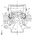
- a hub 10 for a driving wheel of a motor vehicle is rotatably mounted in the suspension standard 11 of the motor vehicle through a bearing unit which includes an outer stationary race 12 having a flange 13 fixed to the standard through bolts (not shown).
- Locked onto the hub 11 is an inner bearing race 14 that forms the inner raceway for one of the two sets of balls 15, 16 of the bearing unit.
- the hub has a cylindrical surface 17 towards its axially outer end, onto which there is fixed a driving ring 18 with outer axial splines 19 for transferring the driving torque from the bell 20 of the constant velocity joint to the hub.
- the driving ring 18 is securely axially locked against the inner bearing race 14 by cold forming, preferably by orbital rolling, of an end edge 21 of the hub.
- the joint bell 20 forms a tubular projection 22 with inner axial splines 23 which couple with the outer splines 19 of the driving ring 18.
- the driving ring 18 and the joint bell 20 are axially removably joined by an elastic open securing ring 24 which is received partly in an inner circular groove 25 of the bell 20, and partly in an outer circular groove 26 of the driving ring 18.
- the locking ring 24 has two radial arms 29 at its end, with axially bent appendixes extending through a slot 27 formed at the axially outer end of the tubular projection 22 of the bell 20. In the drawings, only one of the two arms 29 is shown.
- the sealing device 30 comprises a flexible sealing sleeve 31 of elastomeric material and a circumferential clamping spring 32.
- the sealing sleeve 31 has a main, substantially tubular portion 34 which is sealingly locked by means of the spring 32 around the outer cylindrical surface 33 of the tubular projection 22 of the joint.
- the tubular portion 34 preferably has a free or non-deformed size which is greater than the outer diameter of the cylindrical surface 33, so that the projection 22 may easily be slipped into and out of the sleeve 31.
- the sealing action of the sleeve against the joint bell is ensured mechanically by the spring 32.
- the sleeve 31 has a flange 32 projecting in a radially inner direction that is clamped along its circumference between the joint bell 20 and the hub bearing unit, in this example between a radial end face 36 of the bell on the axially outer side and radial face 37 of the bearing inner race 14.
- the axial clamping of the flange 35 between the two parallel surface of members that are securely locked to one another in the axial direction guarantees a particularly efficient sealing action on the side of the hub bearing unit.
- a part of the flange 35 contacts a conventional sealing device 28, shown schematically, which seals the gap between the bearing races 12 and 14 and which generally comprises a pair of facing annular inserts (not shown) in mutual sliding contact through one or more sealing gaskets.
- the flange 35 should not exert an appreciable pressure against the sealing device 28.
- the axial clamping force of the flange 35 should be exerted by a rigid essentially non deformable element of the hub bearing unit.
- the flange 35 of the sealing device 30 may be clumped between the inner bearing race 14 and the driving ring 18.
- the flange 35 may consist of an annular disk of rigid material onto which the elastomeric sleeve 31 is vulcanized or glued.
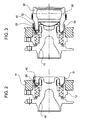
- the latter In order to assemble the constant velocity joint with the hub bearing unit, the latter is preliminarily mounted on the suspension standard ( fig. 2 ).
- the locking ring 24 is fitted in the groove 26 of the driving ring 18.
- the end arms 29 of the locking ring 24 are then contracted together, and this elastic ring is held in this elastically contracted condition in which it is completely contained within the groove 26 of the driving ring 18.
- the two end arms are held one against the other by a retainer tool indicated schematically at 40.
- the sealing sleeve 31 is located around the driving ring 18 with the flange 35 resting adjacent to the face 37 of the inner bearing race 14.
- the joint bell 20 is slipped telescopically with the splines 19 and 23 provided on the outside of the driving ring 18 and in the inside of the tubular projection 22 mutually engaging one another, until the axial outer end face 37 of the bell abuts against the flange 35 of the sleeve 31, which remains axially clamped between the constant velocity joint and the hub bearing unit ( fig. 3 ).
- the tubular portion 34 of the sealing sleeve has a free or non deformed radial size greater than the outer diameter of the cylindrical surface 33 of the constant velocity joint bell, so as to facilitate insertion of the tubular projection 22 into the sleeve during the same assembling step of the joint with the hub bearing unit.
- the circumferential spring 32 is provisionally located on the outer surface of the joint bell, on a cylindrical surface 38 thereof having a diameter that is greater than that of the cylindrical surface 33 of the tubular projection. In the so reached abutting position, the inner groove 25 formed in the tubular projection of the bell is aligned with the groove 26 formed on the outside of the driving ring 18.
- the arms 29 of the elastic ring are released allowing the locking ring 24 to expend and reach its operational position, shown in figure 1 where the ring 24 engages both the aligned grooves 25, 26 and therefore keeps the constant velocity joint axially secured to the hub bearing unit.
- the spring 32 is moved along the joint bell so as to radially clamp the tubular portion 34 of the sleeve against the tubular projection 22 of the joint.
- the hermetic coupling between the hub bearing unit and the constant velocity joint is ensured mechanically, on one side, by the same assembling of this two subassemblies.
- the flange 35 of the elastic sleeve that remains clamped guarantees hermetic sealing at the interface between the two subassemblies.
- the elastic sleeve covers the zone of the slots 27 of the constant velocity joint and is reliably closed by means of circumferential spring 32 which ensures mechanically the sealing action towards the axially inner side.
- the axially inner end of the sleeve is free to expend elastically and allows to easily insert the tool that brings the arms of the locking ring 24 near to one another.
- the constant velocity joint may thus be released and separated from the hub bearing unit without destroying the elastic sleeve.
Abstract
Description
- The present invention refers to a sealing arrangement for the coupling zone between a constant velocity joint and a hub bearing unit of a motor vehicle wheel.
- Arrangements are known from patent publications
US 2002/0070506 A1 andUS 6 354 952 B1 wherein the hub of the wheel receives the driving torque from the bell of the constant velocity joint through a splined coupling. To this end, fixed on the hub is a ring with an axial outer toothing that is inserted in a tubular projection with an inner axial toothing of the outer part or "bell" of the constant velocity joint. The toothed ring and the tubular projection are both provided with a respective circular groove in which an elastic, open locking ring is fitted. This elastic ring has arms at its ends that project through a slot formed at the axially outer end (or outboard end) of the joint bell. -
US 2002/0070506 A1 discloses a sealing arrangement as defined in the preamble of claim 1. Illustrated in fig. 5 ofUS 2002/0070506 A1 is a sealing elastic sleeve which, at one end, is positioned on an outer cylindrical surface of the tubular projection of the joint bell, covering from the outside the said slot and the end arms of the locking ring, and at the other end sealingly cooperates with an annular part fixed to the end to the hub, particularly with an insert of a sealing device of the bearing. - A scarcely efficient sealing allows water to penetrate, especially through the slot formed at the end of the joint bell, into the splined interface zone. Rust formed at the interface of the splined coupling renders the disassembling operation of the hub-bearing unit from the constant velocity joint particularly difficult, besides shortening the life of these members.
- The main object of the invention is to ensure a reliable hermetic sealing for the interface zone between the constant velocity joint and the hub bearing unit. Another object of the invention is to provide a sealing device which may be easily mounted and disassembled during repeated servicing operations throughout the lifetime of the bearing and the joint. A further object of the invention is to guarantee the sealing action without adversely affecting operation of other sealing devices on the hub bearing unit.
- The above and other objects and advantages, which will be better understood in the following, are achieved according to the invention by a sealing device having the features set forth in the appended claims.
- A preferred, but not limiting embodiment of the invention will now be described, reference being made to the accompanying drawings, in which:
-
fig. 1 is an axial cross section view of a sealing device mounted on a constant velocity joint coupled to a hub bearing unit; -
figs. 2-4 are views schematically showing the assembling steps of the assembly shown infig. 1 . - With reference initially to
figure 1 , ahub 10 for a driving wheel of a motor vehicle is rotatably mounted in thesuspension standard 11 of the motor vehicle through a bearing unit which includes an outerstationary race 12 having aflange 13 fixed to the standard through bolts (not shown). Locked onto thehub 11 is an inner bearingrace 14 that forms the inner raceway for one of the two sets ofballs cylindrical surface 17 towards its axially outer end, onto which there is fixed adriving ring 18 with outeraxial splines 19 for transferring the driving torque from thebell 20 of the constant velocity joint to the hub. Thedriving ring 18 is securely axially locked against the inner bearingrace 14 by cold forming, preferably by orbital rolling, of anend edge 21 of the hub. At its axially outer side, thejoint bell 20 forms atubular projection 22 with inneraxial splines 23 which couple with theouter splines 19 of thedriving ring 18. - The
driving ring 18 and thejoint bell 20 are axially removably joined by an elasticopen securing ring 24 which is received partly in an innercircular groove 25 of thebell 20, and partly in an outercircular groove 26 of thedriving ring 18. Thelocking ring 24 has tworadial arms 29 at its end, with axially bent appendixes extending through aslot 27 formed at the axially outer end of thetubular projection 22 of thebell 20. In the drawings, only one of the twoarms 29 is shown. - Indicated overall at 30 is a sealing device for hermetically sealing from the outside the zone of the coupling between the constant velocity joint and the hub bearing unit. The
sealing device 30 comprises aflexible sealing sleeve 31 of elastomeric material and acircumferential clamping spring 32. - The
sealing sleeve 31 has a main, substantiallytubular portion 34 which is sealingly locked by means of thespring 32 around the outercylindrical surface 33 of thetubular projection 22 of the joint. In order to facilitate the assembling and disassembling steps, thetubular portion 34 preferably has a free or non-deformed size which is greater than the outer diameter of thecylindrical surface 33, so that theprojection 22 may easily be slipped into and out of thesleeve 31. The sealing action of the sleeve against the joint bell is ensured mechanically by thespring 32. - At its axially outer side, the
sleeve 31 has aflange 32 projecting in a radially inner direction that is clamped along its circumference between thejoint bell 20 and the hub bearing unit, in this example between aradial end face 36 of the bell on the axially outer side andradial face 37 of the bearinginner race 14. The axial clamping of theflange 35 between the two parallel surface of members that are securely locked to one another in the axial direction guarantees a particularly efficient sealing action on the side of the hub bearing unit. - It will be noticed in
figure 1 that a part of theflange 35 contacts aconventional sealing device 28, shown schematically, which seals the gap between thebearing races device 28, which may be countered if the relative position of its inserts should undergo accidental changes (for example following a stroke), theflange 35 should not exert an appreciable pressure against thesealing device 28. Preferably, as shown in the example offigure 1 , the axial clamping force of theflange 35 should be exerted by a rigid essentially non deformable element of the hub bearing unit. According to a variant (not shown) of the invention, theflange 35 of thesealing device 30 may be clumped between the inner bearingrace 14 and thedriving ring 18. In this case theflange 35 may consist of an annular disk of rigid material onto which theelastomeric sleeve 31 is vulcanized or glued. - In order to assemble the constant velocity joint with the hub bearing unit, the latter is preliminarily mounted on the suspension standard (
fig. 2 ). Thelocking ring 24 is fitted in thegroove 26 of thedriving ring 18. Theend arms 29 of thelocking ring 24 are then contracted together, and this elastic ring is held in this elastically contracted condition in which it is completely contained within thegroove 26 of thedriving ring 18. The two end arms are held one against the other by a retainer tool indicated schematically at 40. The sealingsleeve 31 is located around thedriving ring 18 with theflange 35 resting adjacent to theface 37 of the inner bearingrace 14. - Then (
fig. 3 ) thejoint bell 20 is slipped telescopically with thesplines driving ring 18 and in the inside of thetubular projection 22 mutually engaging one another, until the axialouter end face 37 of the bell abuts against theflange 35 of thesleeve 31, which remains axially clamped between the constant velocity joint and the hub bearing unit (fig. 3 ). As shown infigures 3 and4 , thetubular portion 34 of the sealing sleeve has a free or non deformed radial size greater than the outer diameter of thecylindrical surface 33 of the constant velocity joint bell, so as to facilitate insertion of thetubular projection 22 into the sleeve during the same assembling step of the joint with the hub bearing unit. Thecircumferential spring 32 is provisionally located on the outer surface of the joint bell, on acylindrical surface 38 thereof having a diameter that is greater than that of thecylindrical surface 33 of the tubular projection. In the so reached abutting position, theinner groove 25 formed in the tubular projection of the bell is aligned with thegroove 26 formed on the outside of thedriving ring 18. - By removing the retainer tool (
fig. 4 ), thearms 29 of the elastic ring are released allowing thelocking ring 24 to expend and reach its operational position, shown infigure 1 where thering 24 engages both thealigned grooves spring 32 is moved along the joint bell so as to radially clamp thetubular portion 34 of the sleeve against thetubular projection 22 of the joint. - It will be appreciated that the hermetic coupling between the hub bearing unit and the constant velocity joint is ensured mechanically, on one side, by the same assembling of this two subassemblies. The
flange 35 of the elastic sleeve that remains clamped guarantees hermetic sealing at the interface between the two subassemblies. The elastic sleeve covers the zone of theslots 27 of the constant velocity joint and is reliably closed by means ofcircumferential spring 32 which ensures mechanically the sealing action towards the axially inner side. By removing the circumferential spring to the disassemble the hub bearing unit for the constant velocity joint, the axially inner end of the sleeve is free to expend elastically and allows to easily insert the tool that brings the arms of thelocking ring 24 near to one another. The constant velocity joint may thus be released and separated from the hub bearing unit without destroying the elastic sleeve.
Claims (5)
- A sealing arrangement between a hub bearing unit for a motor vehicle wheel and an associated constant velocity joint, the hub bearing unit including a rotatable hub (10) to which a driving ring (18) is fixed for providing torque transmission to the hub from an outer, rotatable bell member (20) of the constant velocity joint,
the bell member (20) having a tubular projection (22) in telescopic relation with the driving ring (18), and a radial slot (27) axially extending to an end side (36) of the bell member facing a rotatable member (14) of the hub beating unit,
the driving ring (18) and the tubular projection (22) having respective inner (26) and outer (25) circular grooves accommodating a spring locking ring (24) for releasably axially securing the joint bell (20) to the driving ring (18),
the locking ring (24) having arms (29) extending radially outwardly through the slot (27),
a resilient sleeve (31) being fitted with a first end thereof on an outer surface (33) on the tubular projection (22), the radial slot (27) and the arms (29) of the spring locking ring (24) being covered from the outsides, a second other end of the sleeve having a radially inwardly projecting annular flange (35) sealingly cooperating with an annular part secured on the wheel hub (10);
characterised in that
the radially inwardly projecting flange (35) is axially clamped against a rigid annular part (14) secured to or integral with the hub (10), and that
associated with the said first end of the resilient sleeve (31) is a circumferential spring (32) radially and sealingly tightening the first end of the sleeve against the outer cylindrical surface (33) of the tubular projection (22). - A sealing arrangement according to claim 1, characterised in that the flange (35) is axially clamped between the said end side (36) of the joint bell (20) and a rigid annular part (14) secured to or integral with the hub (10).
- A sealing arrangement according to claim 2, characterised in that the flange (35) is axially clamped between the said end side (36) of the joint bell (20) and a radially inner bearing race (14) secured to the hub (10).
- A sealing arrangement according to claim 1, characterised in that the flange (35) is axially clamped between the said driving ring (18) and a radially inner bearing race (14) secured to the hub (10).
- A sealing arrangement according to claim 1, characterised in that the resilient sleeve (31) forms a main, substantially cylindrical portion (34) ending at said first end and having an inner diameter which in a free condition of the sleeve, non-deformed by the circumferential spring (32), is greater than the outer diameter of the outer cylindrical surface (33) of the tubular projection (22).
Priority Applications (6)
| Application Number | Priority Date | Filing Date | Title |
|---|---|---|---|
| EP07100093A EP1942014B1 (en) | 2007-01-04 | 2007-01-04 | A sealing arrangement between a constant velocity joint and a hub bearing unit of a motor vehicle wheel |
| AT07100093T ATE500977T1 (en) | 2007-01-04 | 2007-01-04 | SEAL ARRANGEMENT BETWEEN A CONVERSIONAL JOINT AND A HUB BEARING UNIT OF A MOTOR VEHICLE WHEEL |
| DE602007012991T DE602007012991D1 (en) | 2007-01-04 | 2007-01-04 | Sealing arrangement between a constant velocity joint and a hub bearing unit of a motor vehicle wheel |
| KR1020070134810A KR20080064715A (en) | 2007-01-04 | 2007-12-21 | A sealing arrangement between a constant velocity joint and a hub bearing unit of a motor vehicle wheel |
| JP2007333977A JP2008162582A (en) | 2007-01-04 | 2007-12-26 | Seal structure for coupling zone between constant velocity joint and hub bearing unit of automatic vehicle wheel |
| US11/968,522 US7896750B2 (en) | 2007-01-04 | 2008-01-02 | Sealing arrangement between a constant velocity joint and a hub bearing unit of a motor vehicle wheel |
Applications Claiming Priority (1)
| Application Number | Priority Date | Filing Date | Title |
|---|---|---|---|
| EP07100093A EP1942014B1 (en) | 2007-01-04 | 2007-01-04 | A sealing arrangement between a constant velocity joint and a hub bearing unit of a motor vehicle wheel |
Publications (2)
| Publication Number | Publication Date |
|---|---|
| EP1942014A1 EP1942014A1 (en) | 2008-07-09 |
| EP1942014B1 true EP1942014B1 (en) | 2011-03-09 |
Family
ID=38219495
Family Applications (1)
| Application Number | Title | Priority Date | Filing Date |
|---|---|---|---|
| EP07100093A Active EP1942014B1 (en) | 2007-01-04 | 2007-01-04 | A sealing arrangement between a constant velocity joint and a hub bearing unit of a motor vehicle wheel |
Country Status (6)
| Country | Link |
|---|---|
| US (1) | US7896750B2 (en) |
| EP (1) | EP1942014B1 (en) |
| JP (1) | JP2008162582A (en) |
| KR (1) | KR20080064715A (en) |
| AT (1) | ATE500977T1 (en) |
| DE (1) | DE602007012991D1 (en) |
Cited By (1)
| Publication number | Priority date | Publication date | Assignee | Title |
|---|---|---|---|---|
| CN102848852A (en) * | 2011-06-29 | 2013-01-02 | Skf公司 | Static sealing device for wheel hub assemblies connected to constant velocity joints |
Families Citing this family (7)
| Publication number | Priority date | Publication date | Assignee | Title |
|---|---|---|---|---|
| JP2012183936A (en) * | 2011-03-07 | 2012-09-27 | Jtekt Corp | Rolling bearing device for wheel |
| ITTO20110697A1 (en) * | 2011-07-29 | 2013-01-30 | Skf Ab | PROTECTIVE SHIELD FOR OMOCINETIC JOINTS AND UNIT WHEEL BEARING-SHORTCUT JOINT WITH SUCH A PROTECTION SCREEN |
| US10125854B2 (en) | 2013-09-20 | 2018-11-13 | Bair-Ling Technologies, LLC | Torque limiting system |
| KR101551069B1 (en) * | 2014-03-18 | 2015-09-07 | 현대자동차주식회사 | Apparatus for transferring driving force at wheel for vehicle |
| US11434958B2 (en) * | 2017-05-03 | 2022-09-06 | Neapco Intellectual Property Holdings, Llc | High retention force serviceable plug-on joint assembly |
| WO2019235662A1 (en) * | 2018-06-07 | 2019-12-12 | 주식회사 일진글로벌 | Wheel bearing and wheel bearing assembly |
| JP7111585B2 (en) * | 2018-11-08 | 2022-08-02 | 日立建機株式会社 | Dump truck |
Family Cites Families (17)
| Publication number | Priority date | Publication date | Assignee | Title |
|---|---|---|---|---|
| JPS54176048U (en) * | 1978-05-31 | 1979-12-12 | ||
| JPH07317917A (en) * | 1994-05-25 | 1995-12-08 | Nok Corp | Injection pipe seal |
| DE4425732A1 (en) * | 1994-07-21 | 1996-01-25 | Kugelfischer G Schaefer & Co | Wheel bearing unit with torque sensor for driven wheels of motor vehicle |
| JPH08303448A (en) * | 1995-05-09 | 1996-11-19 | Nok Corp | Cover for joint |
| IT1289779B1 (en) * | 1996-12-20 | 1998-10-16 | Skf Ind Spa | REVERSIBLE LOCKING DEVICE OF A HOMOCINETIC GROUP ON ITS HUB, ESPECIALLY FOR A MOTOR VEHICLE. |
| JP3440777B2 (en) * | 1997-09-10 | 2003-08-25 | 株式会社日立製作所 | Segment type shaft sealing device and drain pump provided with the same |
| JP4408562B2 (en) | 1997-09-10 | 2010-02-03 | ジー・ケー・エヌ・ドライブライン・インターナショナル・ゲゼルシャフト・ミット・ベシュレンクテル・ハフツング | Fixing of members with spring rings |
| JP2001150905A (en) * | 1998-02-16 | 2001-06-05 | Nsk Ltd | Bearing unit for driving wheel |
| JP3982093B2 (en) * | 1998-02-16 | 2007-09-26 | 日本精工株式会社 | Wheel drive axle unit |
| JP2001150903A (en) * | 1999-11-24 | 2001-06-05 | Nsk Ltd | Bearing unit for driving wheel |
| JP2002005185A (en) * | 2000-06-23 | 2002-01-09 | Nsk Ltd | Bearing unit for driving wheel |
| JP2002195280A (en) * | 2000-10-18 | 2002-07-10 | Koyo Seiko Co Ltd | Bearing unit for axle |
| DE20019546U1 (en) | 2000-11-17 | 2002-03-28 | Gkn Automotive Gmbh | sealing arrangement |
| KR100642588B1 (en) * | 2002-09-06 | 2006-11-10 | 닛뽄 세이꼬 가부시기가이샤 | Rolling bearing unit for supporting wheel |
| JP4205477B2 (en) * | 2003-04-24 | 2009-01-07 | ダイキョーニシカワ株式会社 | Resin floor panel structure |
| JP2006064082A (en) * | 2004-08-27 | 2006-03-09 | Jtekt Corp | Rolling bearing unit |
| DE102005018126A1 (en) * | 2005-04-20 | 2006-10-26 | Schaeffler Kg | Wheel bearing joint unit |
-
2007
- 2007-01-04 AT AT07100093T patent/ATE500977T1/en not_active IP Right Cessation
- 2007-01-04 DE DE602007012991T patent/DE602007012991D1/en active Active
- 2007-01-04 EP EP07100093A patent/EP1942014B1/en active Active
- 2007-12-21 KR KR1020070134810A patent/KR20080064715A/en not_active Application Discontinuation
- 2007-12-26 JP JP2007333977A patent/JP2008162582A/en active Pending
-
2008
- 2008-01-02 US US11/968,522 patent/US7896750B2/en active Active
Cited By (1)
| Publication number | Priority date | Publication date | Assignee | Title |
|---|---|---|---|---|
| CN102848852A (en) * | 2011-06-29 | 2013-01-02 | Skf公司 | Static sealing device for wheel hub assemblies connected to constant velocity joints |
Also Published As
| Publication number | Publication date |
|---|---|
| US7896750B2 (en) | 2011-03-01 |
| KR20080064715A (en) | 2008-07-09 |
| US20080174112A1 (en) | 2008-07-24 |
| DE602007012991D1 (en) | 2011-04-21 |
| JP2008162582A (en) | 2008-07-17 |
| ATE500977T1 (en) | 2011-03-15 |
| EP1942014A1 (en) | 2008-07-09 |
Similar Documents
| Publication | Publication Date | Title |
|---|---|---|
| EP1942014B1 (en) | A sealing arrangement between a constant velocity joint and a hub bearing unit of a motor vehicle wheel | |
| EP1950055B1 (en) | Axial coupling of a constant velocity joint to a hub bearing unit of a motor vehicle wheel | |
| US6780114B2 (en) | Drive wheel bearing assembly | |
| WO2010113842A1 (en) | Annular sealing device | |
| EP2778453B1 (en) | Plug-In CVJ assembly | |
| JPH0579861B2 (en) | ||
| EP2127902A1 (en) | Bearing device for driving wheel, and its assembling method | |
| JP2007055322A (en) | Bearing device for vehicle wheel | |
| KR101885139B1 (en) | Sealing apparatus for wheel bearing and manufacturing method thereof | |
| WO2017134981A1 (en) | Constant-velocity universal joint | |
| EP3027921B1 (en) | Overmoulded profile boot can assembly | |
| US8267798B2 (en) | Formed grease cover retention feature | |
| CN108081867B (en) | Wheel hub arrangement for a motor vehicle | |
| EP2202092B1 (en) | Coupling of a constant velocity joint and a hub bearing unit of a motor vehicle wheel | |
| EP3187756B1 (en) | Mechanical seal | |
| EP1508710B1 (en) | A coupling device and a vehicle including such a device | |
| JP6879775B2 (en) | Constant velocity universal joint | |
| JP2008254598A (en) | Wheel supporting device | |
| EP3137780B1 (en) | Reusable dust cap for a pulley assembly | |
| US8371950B2 (en) | Assembly for coupling a constant velocity joint with a motor vehicle hub bearing unit | |
| JP2008075832A (en) | Rolling bearing device | |
| WO2007134157A2 (en) | Driving wheel assembly | |
| KR101689839B1 (en) | Wheel bearing and wheel bearing assembly using the same | |
| WO2019059291A1 (en) | Constant velocity universal joint | |
| JP4738760B2 (en) | Constant velocity joint and wheel hub assembly |
Legal Events
| Date | Code | Title | Description |
|---|---|---|---|
| PUAI | Public reference made under article 153(3) epc to a published international application that has entered the european phase |
Free format text: ORIGINAL CODE: 0009012 |
|
| AK | Designated contracting states |
Kind code of ref document: A1 Designated state(s): AT BE BG CH CY CZ DE DK EE ES FI FR GB GR HU IE IS IT LI LT LU LV MC NL PL PT RO SE SI SK TR |
|
| AX | Request for extension of the european patent |
Extension state: AL BA HR MK RS |
|
| 17P | Request for examination filed |
Effective date: 20090107 |
|
| 17Q | First examination report despatched |
Effective date: 20090213 |
|
| AKX | Designation fees paid |
Designated state(s): AT BE BG CH CY CZ DE DK EE ES FI FR GB GR HU IE IS IT LI LT LU LV MC NL PL PT RO SE SI SK TR |
|
| GRAP | Despatch of communication of intention to grant a patent |
Free format text: ORIGINAL CODE: EPIDOSNIGR1 |
|
| GRAS | Grant fee paid |
Free format text: ORIGINAL CODE: EPIDOSNIGR3 |
|
| GRAA | (expected) grant |
Free format text: ORIGINAL CODE: 0009210 |
|
| AK | Designated contracting states |
Kind code of ref document: B1 Designated state(s): AT BE BG CH CY CZ DE DK EE ES FI FR GB GR HU IE IS IT LI LT LU LV MC NL PL PT RO SE SI SK TR |
|
| REG | Reference to a national code |
Ref country code: GB Ref legal event code: FG4D |
|
| REG | Reference to a national code |
Ref country code: CH Ref legal event code: EP |
|
| REG | Reference to a national code |
Ref country code: IE Ref legal event code: FG4D |
|
| REF | Corresponds to: |
Ref document number: 602007012991 Country of ref document: DE Date of ref document: 20110421 Kind code of ref document: P |
|
| REG | Reference to a national code |
Ref country code: DE Ref legal event code: R096 Ref document number: 602007012991 Country of ref document: DE Effective date: 20110421 |
|
| REG | Reference to a national code |
Ref country code: SE Ref legal event code: TRGR |
|
| REG | Reference to a national code |
Ref country code: NL Ref legal event code: VDEP Effective date: 20110309 |
|
| PG25 | Lapsed in a contracting state [announced via postgrant information from national office to epo] |
Ref country code: ES Free format text: LAPSE BECAUSE OF FAILURE TO SUBMIT A TRANSLATION OF THE DESCRIPTION OR TO PAY THE FEE WITHIN THE PRESCRIBED TIME-LIMIT Effective date: 20110620 Ref country code: LV Free format text: LAPSE BECAUSE OF FAILURE TO SUBMIT A TRANSLATION OF THE DESCRIPTION OR TO PAY THE FEE WITHIN THE PRESCRIBED TIME-LIMIT Effective date: 20110309 Ref country code: LT Free format text: LAPSE BECAUSE OF FAILURE TO SUBMIT A TRANSLATION OF THE DESCRIPTION OR TO PAY THE FEE WITHIN THE PRESCRIBED TIME-LIMIT Effective date: 20110309 Ref country code: GR Free format text: LAPSE BECAUSE OF FAILURE TO SUBMIT A TRANSLATION OF THE DESCRIPTION OR TO PAY THE FEE WITHIN THE PRESCRIBED TIME-LIMIT Effective date: 20110610 |
|
| LTIE | Lt: invalidation of european patent or patent extension |
Effective date: 20110309 |
|
| PG25 | Lapsed in a contracting state [announced via postgrant information from national office to epo] |
Ref country code: NL Free format text: LAPSE BECAUSE OF FAILURE TO SUBMIT A TRANSLATION OF THE DESCRIPTION OR TO PAY THE FEE WITHIN THE PRESCRIBED TIME-LIMIT Effective date: 20110309 Ref country code: SI Free format text: LAPSE BECAUSE OF FAILURE TO SUBMIT A TRANSLATION OF THE DESCRIPTION OR TO PAY THE FEE WITHIN THE PRESCRIBED TIME-LIMIT Effective date: 20110309 Ref country code: FI Free format text: LAPSE BECAUSE OF FAILURE TO SUBMIT A TRANSLATION OF THE DESCRIPTION OR TO PAY THE FEE WITHIN THE PRESCRIBED TIME-LIMIT Effective date: 20110309 Ref country code: AT Free format text: LAPSE BECAUSE OF FAILURE TO SUBMIT A TRANSLATION OF THE DESCRIPTION OR TO PAY THE FEE WITHIN THE PRESCRIBED TIME-LIMIT Effective date: 20110309 Ref country code: BG Free format text: LAPSE BECAUSE OF FAILURE TO SUBMIT A TRANSLATION OF THE DESCRIPTION OR TO PAY THE FEE WITHIN THE PRESCRIBED TIME-LIMIT Effective date: 20110609 Ref country code: CY Free format text: LAPSE BECAUSE OF FAILURE TO SUBMIT A TRANSLATION OF THE DESCRIPTION OR TO PAY THE FEE WITHIN THE PRESCRIBED TIME-LIMIT Effective date: 20110309 |
|
| PG25 | Lapsed in a contracting state [announced via postgrant information from national office to epo] |
Ref country code: BE Free format text: LAPSE BECAUSE OF FAILURE TO SUBMIT A TRANSLATION OF THE DESCRIPTION OR TO PAY THE FEE WITHIN THE PRESCRIBED TIME-LIMIT Effective date: 20110309 |
|
| PG25 | Lapsed in a contracting state [announced via postgrant information from national office to epo] |
Ref country code: EE Free format text: LAPSE BECAUSE OF FAILURE TO SUBMIT A TRANSLATION OF THE DESCRIPTION OR TO PAY THE FEE WITHIN THE PRESCRIBED TIME-LIMIT Effective date: 20110309 Ref country code: PT Free format text: LAPSE BECAUSE OF FAILURE TO SUBMIT A TRANSLATION OF THE DESCRIPTION OR TO PAY THE FEE WITHIN THE PRESCRIBED TIME-LIMIT Effective date: 20110711 |
|
| PG25 | Lapsed in a contracting state [announced via postgrant information from national office to epo] |
Ref country code: CZ Free format text: LAPSE BECAUSE OF FAILURE TO SUBMIT A TRANSLATION OF THE DESCRIPTION OR TO PAY THE FEE WITHIN THE PRESCRIBED TIME-LIMIT Effective date: 20110309 Ref country code: RO Free format text: LAPSE BECAUSE OF FAILURE TO SUBMIT A TRANSLATION OF THE DESCRIPTION OR TO PAY THE FEE WITHIN THE PRESCRIBED TIME-LIMIT Effective date: 20110309 Ref country code: IS Free format text: LAPSE BECAUSE OF FAILURE TO SUBMIT A TRANSLATION OF THE DESCRIPTION OR TO PAY THE FEE WITHIN THE PRESCRIBED TIME-LIMIT Effective date: 20110709 Ref country code: SK Free format text: LAPSE BECAUSE OF FAILURE TO SUBMIT A TRANSLATION OF THE DESCRIPTION OR TO PAY THE FEE WITHIN THE PRESCRIBED TIME-LIMIT Effective date: 20110309 |
|
| PLBE | No opposition filed within time limit |
Free format text: ORIGINAL CODE: 0009261 |
|
| STAA | Information on the status of an ep patent application or granted ep patent |
Free format text: STATUS: NO OPPOSITION FILED WITHIN TIME LIMIT |
|
| 26N | No opposition filed |
Effective date: 20111212 |
|
| PG25 | Lapsed in a contracting state [announced via postgrant information from national office to epo] |
Ref country code: PL Free format text: LAPSE BECAUSE OF FAILURE TO SUBMIT A TRANSLATION OF THE DESCRIPTION OR TO PAY THE FEE WITHIN THE PRESCRIBED TIME-LIMIT Effective date: 20110309 Ref country code: DK Free format text: LAPSE BECAUSE OF FAILURE TO SUBMIT A TRANSLATION OF THE DESCRIPTION OR TO PAY THE FEE WITHIN THE PRESCRIBED TIME-LIMIT Effective date: 20110309 |
|
| REG | Reference to a national code |
Ref country code: DE Ref legal event code: R097 Ref document number: 602007012991 Country of ref document: DE Effective date: 20111212 |
|
| PG25 | Lapsed in a contracting state [announced via postgrant information from national office to epo] |
Ref country code: MC Free format text: LAPSE BECAUSE OF NON-PAYMENT OF DUE FEES Effective date: 20120131 |
|
| REG | Reference to a national code |
Ref country code: CH Ref legal event code: PL |
|
| REG | Reference to a national code |
Ref country code: IE Ref legal event code: MM4A |
|
| PG25 | Lapsed in a contracting state [announced via postgrant information from national office to epo] |
Ref country code: LI Free format text: LAPSE BECAUSE OF NON-PAYMENT OF DUE FEES Effective date: 20120131 Ref country code: CH Free format text: LAPSE BECAUSE OF NON-PAYMENT OF DUE FEES Effective date: 20120131 |
|
| PG25 | Lapsed in a contracting state [announced via postgrant information from national office to epo] |
Ref country code: IE Free format text: LAPSE BECAUSE OF NON-PAYMENT OF DUE FEES Effective date: 20120104 |
|
| PG25 | Lapsed in a contracting state [announced via postgrant information from national office to epo] |
Ref country code: TR Free format text: LAPSE BECAUSE OF FAILURE TO SUBMIT A TRANSLATION OF THE DESCRIPTION OR TO PAY THE FEE WITHIN THE PRESCRIBED TIME-LIMIT Effective date: 20110309 |
|
| PG25 | Lapsed in a contracting state [announced via postgrant information from national office to epo] |
Ref country code: LU Free format text: LAPSE BECAUSE OF NON-PAYMENT OF DUE FEES Effective date: 20120104 |
|
| PG25 | Lapsed in a contracting state [announced via postgrant information from national office to epo] |
Ref country code: HU Free format text: LAPSE BECAUSE OF FAILURE TO SUBMIT A TRANSLATION OF THE DESCRIPTION OR TO PAY THE FEE WITHIN THE PRESCRIBED TIME-LIMIT Effective date: 20070104 |
|
| REG | Reference to a national code |
Ref country code: FR Ref legal event code: PLFP Year of fee payment: 10 |
|
| REG | Reference to a national code |
Ref country code: FR Ref legal event code: PLFP Year of fee payment: 11 |
|
| PGFP | Annual fee paid to national office [announced via postgrant information from national office to epo] |
Ref country code: FR Payment date: 20170126 Year of fee payment: 11 Ref country code: SE Payment date: 20170126 Year of fee payment: 11 |
|
| PGFP | Annual fee paid to national office [announced via postgrant information from national office to epo] |
Ref country code: GB Payment date: 20170131 Year of fee payment: 11 |
|
| PGFP | Annual fee paid to national office [announced via postgrant information from national office to epo] |
Ref country code: IT Payment date: 20170124 Year of fee payment: 11 |
|
| REG | Reference to a national code |
Ref country code: SE Ref legal event code: EUG |
|
| GBPC | Gb: european patent ceased through non-payment of renewal fee |
Effective date: 20180104 |
|
| PG25 | Lapsed in a contracting state [announced via postgrant information from national office to epo] |
Ref country code: FR Free format text: LAPSE BECAUSE OF NON-PAYMENT OF DUE FEES Effective date: 20180131 Ref country code: SE Free format text: LAPSE BECAUSE OF NON-PAYMENT OF DUE FEES Effective date: 20180105 |
|
| REG | Reference to a national code |
Ref country code: FR Ref legal event code: ST Effective date: 20180928 |
|
| PG25 | Lapsed in a contracting state [announced via postgrant information from national office to epo] |
Ref country code: GB Free format text: LAPSE BECAUSE OF NON-PAYMENT OF DUE FEES Effective date: 20180104 |
|
| PG25 | Lapsed in a contracting state [announced via postgrant information from national office to epo] |
Ref country code: IT Free format text: LAPSE BECAUSE OF NON-PAYMENT OF DUE FEES Effective date: 20180104 |
|
| PGFP | Annual fee paid to national office [announced via postgrant information from national office to epo] |
Ref country code: DE Payment date: 20230127 Year of fee payment: 17 |
|
| P01 | Opt-out of the competence of the unified patent court (upc) registered |
Effective date: 20230513 |