EP1308114A2 - Cuiseur vapeur multifonctions à autonomie améliorée - Google Patents
Cuiseur vapeur multifonctions à autonomie améliorée Download PDFInfo
- Publication number
- EP1308114A2 EP1308114A2 EP02356213A EP02356213A EP1308114A2 EP 1308114 A2 EP1308114 A2 EP 1308114A2 EP 02356213 A EP02356213 A EP 02356213A EP 02356213 A EP02356213 A EP 02356213A EP 1308114 A2 EP1308114 A2 EP 1308114A2
- Authority
- EP
- European Patent Office
- Prior art keywords
- cooking
- steam
- receptacle
- steam cooker
- cooker according
- Prior art date
- Legal status (The legal status is an assumption and is not a legal conclusion. Google has not performed a legal analysis and makes no representation as to the accuracy of the status listed.)
- Granted
Links
Images

Classifications
-
- A—HUMAN NECESSITIES
- A47—FURNITURE; DOMESTIC ARTICLES OR APPLIANCES; COFFEE MILLS; SPICE MILLS; SUCTION CLEANERS IN GENERAL
- A47J—KITCHEN EQUIPMENT; COFFEE MILLS; SPICE MILLS; APPARATUS FOR MAKING BEVERAGES
- A47J27/00—Cooking-vessels
- A47J27/04—Cooking-vessels for cooking food in steam; Devices for extracting fruit juice by means of steam ; Vacuum cooking vessels
-
- A—HUMAN NECESSITIES
- A47—FURNITURE; DOMESTIC ARTICLES OR APPLIANCES; COFFEE MILLS; SPICE MILLS; SUCTION CLEANERS IN GENERAL
- A47J—KITCHEN EQUIPMENT; COFFEE MILLS; SPICE MILLS; APPARATUS FOR MAKING BEVERAGES
- A47J27/00—Cooking-vessels
- A47J27/14—Cooking-vessels for use in hotels, restaurants, or canteens
- A47J27/16—Cooking-vessels for use in hotels, restaurants, or canteens heated by steam
- A47J27/17—Cooking-vessels for use in hotels, restaurants, or canteens heated by steam with steam jacket
Definitions
- the present invention relates to the general technical field of apparatus or steam cooking utensils and relates more particularly to multifunction steamers intended for cooking on a perforated support as well as in a container.
- Steam cooking appliance or utensil has a base provided for the production of steam supplying a cooking chamber.
- the device steam cooking includes heating means, for example electric, while the cookware does not have it.
- the cooking chamber generally has a bottom receptacle surmounted one or more cooking vessels or supports, and a cover.
- the lower receptacle allows the collection of cooking juices or condensates.
- the cooking chamber may have an independent external wall cooking vessels and / or supports, and / or the collecting receptacle.
- a cooking container suitable for such slow cooking has a side wall and a bottom without openings. A lid closing the cooking container protects food from steam. Calories are transferred to food through the walls.
- Steaming dry foods such as rice is done in water and uses a cooking container with a bottom without openings and a side wall whose lower part is also devoid openings. It is best not to use a cover to close the cooking container. Indeed the absence of a cover allows the steam to be in contact with food or liquid to speed up cooking.
- the liquid preparations such as sauces or soups can also be cooked or reheated in this way.
- the object of the present invention is to provide a steam cooker allowing to reconcile condensate recycling and collection in a simple way separated from the cooking juices.
- Another object of the present invention is to provide a steam cooker of the aforementioned type, in which the use of cooking juices is facilitated.
- a steamer including a water tank supplying or constituting a steam production chamber, an enclosure cooking, supplied with steam by the steam production chamber, comprising an intermediate collecting receptacle having a means of spill into the water tank, in which are likely to be arranged a cooking container and / or a cooking support having a flow means in the intermediate collecting receptacle, because the discharge means is associated with a removable closure means.
- cooking container is meant a container having a full bottom and solid side walls high enough to avoid overflow or falling food. Steam can reach food if container is without cover. However, the cooking juices remain contained in the container.
- the container can be closed with a lid for slow cooking simmering type stew, at a temperature below 100 ° C.
- cooking support having a flow means means a support having lower and / or lateral openings, and / or side cutouts for draining cooking juices. Steam can therefore pass through the support through said openings or cutouts and pass around food.
- Removable closure means allows the user to use the receptacle intermediate collector either as a condensate drain to the tank of water, or as a pan for cooking juices.
- the user When the food is placed on the cooking support, the user sets places the closure means to plug the discharge means of the intermediate collector receptacle. This provision prevents juices from from food placed on the cooking support does not cloud the water of the tank. User can easily access the collected cooking juices in the intermediate collecting receptacle.
- the user thus has a versatile and efficient device.
- the closure means is integral with the collecting receptacle intermediate. This provision prevents the user from losing the means shutter.
- the sealing means can be independent or still be attached to another element of the steamer.
- the closure means is formed by a valve.
- a valve comprising a sealing surface connected to a rod engaged in the means spill, the rod being articulated relative to a lever along an axis off-center articulation, the lever comprising a bearing surface whose radius with respect to the offset axis of articulation is increasing between a first zone, in which the closure surface releases the discharge means, and a second zone, in which the bearing surface is in contact with a face of the intermediate collecting receptacle to maintain the surface shutter against an opposite face of said receptacle. So the position of the lever makes it possible to control the sealing or not of the discharge means by the valve.
- the discharge means is an orifice formed in a wall of the intermediate collecting receptacle, the sealing surface being a ring, the rod being from the interior of said ring.
- the orifice can then be formed in the bottom of the intermediate collecting receptacle.
- the articulation between the rod and the lever is formed by two aligned pins, axially engaged in two cavities having each one a lateral cut allowing the insertion in force of said tenons.
- This arrangement facilitates assembly.
- the lever comprises two flanges each carrying one studs on their inner face, the bearing surface being formed on the periphery of the flanges.
- Such a part can easily be obtained by molding.
- the flanges are joined by a tab.
- the user can thus easily operate the lever.
- the lever is arranged on an inner face of the intermediate collector receptacle.
- the lever when the receptacle intermediate collector is in place on the water tank, the user can access the lever without having to remove said receptacle.
- the sealing surface is formed by a mounted seal on a collar secured to the rod.
- the joint can in particular be mounted on the intermediate collecting receptacle.
- the closure means is formed by a flexible stopper.
- FIG. 1 shows an electric steam cooker comprising a base 1, designed for steam production, comprising a water tank 2 and a heating element 3 associated with an electronic control device 9 allowing operation at full power during an initial phase of temperature rise and reduced power operation during cooking phase.
- the reduced power can be supplied continuously or by alternating heating periods and stopping periods.
- An annular wall 4 is arranged around the heating element 3.
- the wall 4 is provided with a lower passage 5 separating the reservoir 2 from a chamber for producing steam 6.
- the base 1 is surmounted by a cooking enclosure 10 comprising a bottom 11, side walls 12, 13, 14 and a cover 15.
- the cover has a domed inner face 16, a gripping member 17 and a vent 18.
- An intermediate collecting receptacle 20 arranged on the base 1 forms the bottom 11 of the cooking chamber 10.
- the receptacle 20 has a peripheral wall 21 supporting the side wall 12.
- the wall 21 surrounds a basin 22 provided for collecting juice or condensate.
- An annular wall 23 rises from the bottom of the basin 22.
- the wall 23 has orifices 24 provided for the passage of the steam from chamber 6.
- the receptacle 20 has a means of spill 25 associated with a removable closure means 26. Way to spill 25 is formed by an orifice in the bottom of the basin 22.
- the closure means 26 is formed by a flexible plug 27 connected to the receptacle 20 by a clip 28.
- the flexible stopper 27 is for example made of elastomer.
- a cooking support 30 is mounted on an internal rim of the wall 12.
- the cooking support 30 is formed by a removable perforated plate 31.
- the perforations 32 of the plate 31 form a means of flow 33 towards the receptacle 20 disposed under said plate.
- a cooking container 40 has a bottom 41 and a side wall 42 free of perforations up to the top of an upper rim 43. Openings 44 formed in the wall 45 connecting the container 40 to the wall support device 14 allow steam to reach the inside 16 of the cover 15, to form condensates. Due to the curved shape from the inner face 16, the condensates slide along said face to form a liquid seal by condensation at the rim 43, due to the small distance formed between said flange 43 and said face 16. The vapor issuing of the steam production chamber 6 then continues to heat the bottom 41 and the side wall 42 of the cooking container 40, without penetrating inside of said container.
- condensate can form on the walls of the cooking chamber outside the container 40 and fall back into the collecting receptacle 20.
- the user can remove the plug 27.
- the condensate collected in receptacle 20 can then fall back into the tank 2 and supply the steam production chamber 6 again.
- the recycling of condensates can also be considered during cooking in a container placed on the support 30. In fact, the cooking juices remain confined in said container.
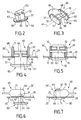
- FIGS. 2 to 7 A second embodiment is illustrated in FIGS. 2 to 7, in which the shutter means 26 'is formed by a valve 50 articulated with respect to a lever 60 along an off-center hinge axis 61.
- the valve 50 has a sealing surface 51 connected to an articulated rod 52 relative to the lever 60.
- the closure surface 51 is a ring and the rod 52 comes from inside this ring.
- the shutter surface 51 is formed by a seal 57 mounted on a flange 58 secured to the rod 52.
- the rod 52 is engaged in an orifice forming the discharge means 25, formed in the bottom of receptacle 20.
- Two cavities 53, 54 belonging to the joint are formed on the rod 52.
- the lever 60 has two flanges 67, 68 joined by a tongue 69.
- the inner face of each of the flanges 67, 68 carries a stud 65, 66.
- the two tenons 65, 66 are aligned.
- the axis of the pins 65, 66 forms the off-center axis 61 of the joint.
- Leverage 60 is arranged on an inner face 29 of the receptacle 20.
- the lever 60 has a bearing surface 62 comprising with respect to the offset articulation axis 61 an increasing radius between a first support zone 63 and a second zone support 64.
- the bearing surface 62 is extended on either side of the bearing zones 63, 64 on the one hand by a first rest zone 70 and on the other hand by a second rest zone 71.
- the rest zones 70, 71 are formed by two faces, advantageously opposite, of the periphery of each of the flanges 67, 68.
- the first rest zone 70 is connected to the second rest zone 71 by a circular sector on which support areas 63, 64 are provided.
- the articulation between the rod 52 and the lever 60 is formed by the two pins 65, 66 engaged axially in the cavities 53, 54.
- the cavities 53, 54 have each a lateral cutout 55, 56 allowing the forceful insertion of the studs 65, 66.
- the support zone 63 is located near the face 29 of the receptacle 20.
- the support area 63 being close to the off-center axis 61, the rod 52 articulated on the axis 51 is in position low relative to the discharge means 25.
- the closure surface 51 is away from the opposite face of the receptacle 20 and frees the discharge orifice 25.
- the lever 60 then occupies a recommended position during slow cooking or simmer. The recycling of condensates increases the autonomy of cooking.
- the bearing area 64 is located near the face 29 of the receptacle 20.
- the support area 64 being distant from the off-center axis 61, the rod 52 articulated on the axis 51 is in position high with respect to the discharge means 25.
- the closure surface 51 is held against the opposite side of the receptacle 20.
- the discharge opening 25 is closed.
- the lever 60 then occupies a position recommended during a steam cooking. The user collects the cooking juices in the receptacle 20.
- the user thus has an efficient and convenient steam cooker instructions, allowing to carry out several types of steam cooking.
- the user operates the lever 60 by means of the tab 69.
- the support of the lever 60 on the receptacle 20 is transferred from the rest zone 70 to the rest zone 71 via the support zones 63, 64, and vice versa.
- the plug 27 can be made of a rigid material. A seal can then be provided on the cap or in the receptacle. Attachment 28 is not essential.
- the lever 60 can be mounted on the underside of receptacle 20.
- a spring is then necessary to push back the rod 52 in order to release the discharge means 25.
- the pins 65, 66 can be mounted on the rod 52, the housings or cavities 53, 54 then being formed in the lever 60.
- the seal 57 can be formed around the discharge means 25.
- the discharge means 25 is not necessarily formed in the bottom of the receptacle 20, but can be arranged in a side wall adjacent to the bottom of the receptacle 20.
- the cooking container 40 can be combined to a cover independent of the cover of the cooking chamber 10, or be without cover.
Landscapes
- Engineering & Computer Science (AREA)
- Food Science & Technology (AREA)
- Cookers (AREA)
- Fodder In General (AREA)
- Processing Of Solid Wastes (AREA)
- Commercial Cooking Devices (AREA)
- Distillation Of Fermentation Liquor, Processing Of Alcohols, Vinegar And Beer (AREA)
- Soy Sauces And Products Related Thereto (AREA)
- Meat, Egg Or Seafood Products (AREA)
Abstract
- L'invention concerne un cuiseur vapeur comprenant un réservoir d'eau (2) alimentant ou constituant une chambre de production de vapeur (6), une enceinte de cuisson (10), alimentée en vapeur par la chambre de production de vapeur (6), comportant un réceptacle collecteur intermédiaire (20) présentant un moyen de déversement (25) dans le réservoir d'eau (2), dans laquelle sont susceptibles d'être agencés un récipient de cuisson (40) et/ou un support de cuisson (30) présentant un moyen d'écoulement (33) dans le réceptacle collecteur intermédiaire (20).
- Conformément à l'invention, le moyen de déversement (25) est associé à un moyen d'obturation (26) amovible.
Description
- la figure 1 est une section verticale d'un cuiseur vapeur électrique selon l'invention, comportant un premier exemple de réalisation du moyen d'obturation de l'ouverture de déversement du réceptacle collecteur intermédiaire,
- les figures 2 et 3 sont deux vues en perspective des deux éléments d'un deuxième exemple de réalisation du moyen d'obturation de l'ouverture de déversement du réceptacle collecteur intermédiaire,
- les figures 4 et 5 sont deux vues frontales du deuxième exemple de réalisation, respectivement en position ouverte et en position fermée,
- les figures 6 et 7 sont deux vues latérales du deuxième exemple de réalisation, respectivement en position ouverte et en position fermée.
Claims (10)
- Cuiseur vapeur comprenant un réservoir d'eau (2) alimentant ou constituant une chambre de production de vapeur (6), une enceinte de cuisson (10), alimentée en vapeur par la chambre de production de vapeur (6), comportant un réceptacle collecteur intermédiaire (20) présentant un moyen de déversement (25) dans le réservoir d'eau (2), dans laquelle sont susceptibles d'être agencés un récipient de cuisson (40) et/ou un support de cuisson (30) présentant un moyen d'écoulement (33) dans le réceptacle collecteur intermédiaire (20), caractérisé en ce que le moyen de déversement (25) est associé à un moyen d'obturation (26 ; 26') amovible.
- Cuiseur vapeur selon la revendication 1, caractérisé en ce que le moyen d'obturation (26 ; 26') est solidaire du réceptacle collecteur intermédiaire (20).
- Cuiseur vapeur selon l'une des revendications 1 ou 2, caractérisé en ce que le moyen d'obturation (26') est formé par un clapet (50) comportant une surface d'obturation (51) reliée à une tige (52) engagée dans le moyen de déversement (25), la tige (52) étant articulée par rapport à un levier (60) selon un axe d'articulation décentré (61), le levier (60) comportant une surface d'appui (62) dont le rayon par rapport à l'axe d'articulation décentré (61) est croissant entre une première zone (63), dans laquelle la surface d'obturation (51) libère le moyen de déversement (25), et une deuxième zone (64), dans laquelle la surface d'appui (62) est en contact avec une face du réceptacle collecteur intermédiaire (20) pour maintenir la surface d'obturation (51) contre une face opposée dudit réceptacle.
- Cuiseur vapeur selon la revendication 3, caractérisé en ce que le moyen de déversement (26) est un orifice ménagé dans une paroi du réceptacle collecteur intermédiaire (20), la surface d'obturation (51) étant un anneau, la tige (52) étant issue de l'intérieur dudit anneau.
- Cuiseur vapeur selon l'une des revendications 3 ou 4, caractérisé en ce que l'articulation entre la tige (52) et le levier (60) est formée par deux tenons (65, 66) alignés, engagés axialement dans deux cavités (53, 54) présentant chacune une découpe latérale (55, 56) permettant l'insertion en force desdits tenons.
- Cuiseur vapeur selon la revendication 5, caractérisé en ce que le levier (60) comporte deux flasques (67, 68) portant chacune l'un des tenons (65, 66) sur leur face intérieure, la surface d'appui (62) étant ménagée sur la périphérie des flasques (67, 68).
- Cuiseur vapeur selon la revendication 6, caractérisé en ce que les flasques (67, 68) sont réunies par une languette (69).
- Cuiseur vapeur selon l'une des revendications 3 à 7, caractérisé en ce que le levier (60) est agencé sur une face intérieure (29) du réceptacle collecteur intermédiaire (20).
- Cuiseur vapeur selon l'une des revendications 3 à 8, caractérisé en ce que la surface d'obturation (51) est formée par un joint (57) monté sur une collerette (58) solidaire de la tige (52).
- Cuiseur vapeur selon l'une des revendications 1 ou 2, caractérisé en ce que le moyen d'obturation (26) est formé par un bouchon souple (27).
Applications Claiming Priority (2)
| Application Number | Priority Date | Filing Date | Title |
|---|---|---|---|
| FR0114345 | 2001-11-06 | ||
| FR0114345A FR2831783B1 (fr) | 2001-11-06 | 2001-11-06 | Cuiseur vapeur multifonctions a autonomie amelioree |
Publications (3)
| Publication Number | Publication Date |
|---|---|
| EP1308114A2 true EP1308114A2 (fr) | 2003-05-07 |
| EP1308114A3 EP1308114A3 (fr) | 2003-08-13 |
| EP1308114B1 EP1308114B1 (fr) | 2006-11-29 |
Family
ID=8869115
Family Applications (1)
| Application Number | Title | Priority Date | Filing Date |
|---|---|---|---|
| EP02356213A Expired - Lifetime EP1308114B1 (fr) | 2001-11-06 | 2002-10-28 | Cuiseur vapeur multifonctions à autonomie améliorée |
Country Status (6)
| Country | Link |
|---|---|
| US (1) | US6655264B2 (fr) |
| EP (1) | EP1308114B1 (fr) |
| CN (1) | CN1251635C (fr) |
| AT (1) | ATE346527T1 (fr) |
| DE (1) | DE60216397T2 (fr) |
| FR (1) | FR2831783B1 (fr) |
Families Citing this family (20)
| Publication number | Priority date | Publication date | Assignee | Title |
|---|---|---|---|---|
| GB2375703B (en) * | 2000-12-22 | 2004-12-29 | Seb Sa | Utensil for slow-cooking with steam |
| JP3708107B2 (ja) * | 2004-03-18 | 2005-10-19 | シャープ株式会社 | 蒸気発生装置及びこれを搭載した蒸気調理器 |
| US7208702B2 (en) * | 2004-11-22 | 2007-04-24 | Goodway Electrical Co., Ltd. | Steam cooker |
| WO2006102214A2 (fr) * | 2005-03-21 | 2006-09-28 | Salton, Inc. | Cuiseur a vapeur a compartiments multiples |
| US8720325B2 (en) | 2010-04-29 | 2014-05-13 | Whirlpool Corporation | Food processor with a lockable adjustable blade assembly |
| US10449685B2 (en) | 2010-04-29 | 2019-10-22 | Whirlpool Corporation | Food processor with adjustable blade assembly |
| WO2012013825A1 (fr) * | 2011-03-29 | 2012-02-02 | Gurris Gmbh | Couvercle perméable à la vapeur, récipient muni de celui-ci et rôtissoire pour poulet |
| CN102551512B (zh) * | 2012-01-18 | 2014-07-16 | 浙江苏泊尔家电制造有限公司 | 电蒸锅的蒸汽发生装置 |
| CN103371715B (zh) * | 2012-04-20 | 2016-02-24 | 宁波市安通机械有限公司 | 一种食物加热器 |
| CN102823780B (zh) * | 2012-08-21 | 2016-02-03 | 布勒(广州)食品机械有限公司 | 粉团连续蒸煮设备及其工艺 |
| US10085599B2 (en) | 2014-12-19 | 2018-10-02 | Whirlpool Corporation | Multi-cook and food processing prep product |
| FR3051647B1 (fr) * | 2016-05-31 | 2018-06-01 | Seb S.A. | Accessoire cuiseur vapeur pour chauffer et/ou cuire a la vapeur des aliments contenus dans un recipient |
| US20180110373A1 (en) * | 2016-10-21 | 2018-04-26 | Koninklijke Philips N.V. | Food processor with improved steam channel structure |
| CN107252246B (zh) * | 2017-07-15 | 2020-05-26 | 广东汇莱德温控器有限公司 | 蒸汽锅 |
| CN107319914B (zh) * | 2017-07-15 | 2020-05-26 | 广东汇莱德温控器有限公司 | 蒸汽内锅双腔式蒸汽锅 |
| CN109419312B (zh) * | 2017-09-05 | 2021-10-12 | 佛山市顺德区美的电热电器制造有限公司 | 电烹饪器及用于电烹饪器的再加热方法 |
| KR102023172B1 (ko) * | 2017-11-07 | 2019-09-19 | 항저우 시앙티엔 테크놀로지 컴퍼니 리미티드 | 전기밥솥 |
| CN108814260B (zh) * | 2018-07-20 | 2020-12-01 | 绍兴市柯桥区欣飞科技有限公司 | 节能健康止逸汽锅 |
| CN109247497A (zh) * | 2018-08-27 | 2019-01-22 | 湖州吴兴久虹机械有限公司 | 一种粽子蒸煮箱 |
| CN112716270B (zh) * | 2020-12-23 | 2022-04-15 | 广西贵港市西江节能锅炉有限公司 | 一种多功能蒸汽灶 |
Family Cites Families (10)
| Publication number | Priority date | Publication date | Assignee | Title |
|---|---|---|---|---|
| DE271877C (fr) * | ||||
| DE3304058A1 (de) * | 1983-02-07 | 1984-08-09 | MKT Gesellschaft für Metallbau und Kunststofftechnik mbH, 8080 Fürstenfeldbruck | Heissluftdaempfer |
| US4509412B1 (en) | 1983-03-04 | 1994-01-11 | Rival Manufacturing Company | Food steaming device |
| US4485801A (en) * | 1983-10-25 | 1984-12-04 | Wyndham Hodges | Cooking utensils |
| US4739698A (en) | 1987-04-14 | 1988-04-26 | Allaire Pascal M | Apparatus and method for cooking with steam |
| US5275094A (en) * | 1993-05-17 | 1994-01-04 | Black & Decker Inc. | Divider basket for steam cooking utensil |
| FR2786083B1 (fr) * | 1998-11-19 | 2001-01-05 | Seb Sa | Cuiseur a vapeur a remplissage lateral d'eau |
| US6125738A (en) * | 1999-10-13 | 2000-10-03 | Poister; Clarence E. | Cooking device for separating and retaining fat from foods during cooking |
| US6267046B1 (en) * | 2000-02-28 | 2001-07-31 | Conair Corporation | Convection steamer |
| FR2823962B1 (fr) * | 2001-04-26 | 2003-08-01 | Seb Sa | Appareil electromenager de cuisson a la vapeur a degagement de vapeur reduit |
-
2001
- 2001-11-06 FR FR0114345A patent/FR2831783B1/fr not_active Expired - Fee Related
-
2002
- 2002-10-28 AT AT02356213T patent/ATE346527T1/de not_active IP Right Cessation
- 2002-10-28 EP EP02356213A patent/EP1308114B1/fr not_active Expired - Lifetime
- 2002-10-28 DE DE60216397T patent/DE60216397T2/de not_active Expired - Lifetime
- 2002-11-05 CN CNB02150217XA patent/CN1251635C/zh not_active Expired - Fee Related
- 2002-11-05 US US10/287,652 patent/US6655264B2/en not_active Expired - Fee Related
Also Published As
| Publication number | Publication date |
|---|---|
| CN1251635C (zh) | 2006-04-19 |
| DE60216397T2 (de) | 2007-09-27 |
| US6655264B2 (en) | 2003-12-02 |
| DE60216397D1 (de) | 2007-01-11 |
| ATE346527T1 (de) | 2006-12-15 |
| CN1416768A (zh) | 2003-05-14 |
| FR2831783B1 (fr) | 2004-01-09 |
| FR2831783A1 (fr) | 2003-05-09 |
| EP1308114A3 (fr) | 2003-08-13 |
| EP1308114B1 (fr) | 2006-11-29 |
| US20030084790A1 (en) | 2003-05-08 |
Similar Documents
| Publication | Publication Date | Title |
|---|---|---|
| EP1308114B1 (fr) | Cuiseur vapeur multifonctions à autonomie améliorée | |
| EP3079530B1 (fr) | Appareil electrique de chauffage et/ou de cuisson d'aliments a la vapeur | |
| EP3558071B1 (fr) | Accessoire cuiseur vapeur modulaire pour chauffer et/ou cuire à la vapeur des aliments contenus dans un récipient | |
| EP3463002B1 (fr) | Accessoire cuiseur vapeur pour chauffer et/ou cuire a la vapeur des aliments contenus dans un récipient | |
| EP1922967B1 (fr) | Appareil électroménager de préparation culinaire chauffant, comportant un récipient de cuisson intermédiaire | |
| EP1343401B1 (fr) | Ustensile pour la cuisson lente a la vapeur | |
| EP1555919B1 (fr) | Base de production de vapeur pour cuiseur vapeur comportant un support a aromates | |
| EP1380242B1 (fr) | Base chauffante pour appareil de production de vapeur | |
| EP1504705B1 (fr) | Appareil électrique de cuisson comportant un socle de vidange | |
| EP2071985B1 (fr) | Cuiseur vapeur avec dispositif de remplissage | |
| EP2574259B1 (fr) | Cuiseur vapeur avec dispositif de remplissage du réservoir d'eau en cours de cuisson | |
| FR2846216A1 (fr) | Base de production de vapeur pour cuiseur vapeur, comportant un support a aromates | |
| EP2407070B1 (fr) | Element de cuisson, notamment pour appareil electrique de cuisson | |
| EP1504706B1 (fr) | Appareil électrique de cuisson comportant un socle d'alimentation électrique | |
| FR2818523A1 (fr) | Ustensile pour la cuisson lente a la vapeur | |
| FR2896977A1 (fr) | Ensemble pour la cuisson a la vapeur, comportant un panier de cuisson associe a un organe de prehension exterieur | |
| FR2846215A1 (fr) | Accessoire de cuisson pour appareil ou ustensile de cuisson a la vapeur prevu pour realiser des preparations simultanees | |
| WO2007088281A1 (fr) | Ensemble pour la cuisson a la vapeur, comportant des paniers de cuisson juxtaposes | |
| WO2020115242A1 (fr) | Accessoire cuiseur vapeur avec bouchon amovible | |
| WO2020115246A1 (fr) | Accessoire cuiseur vapeur avec dispositif de support pourvu de nervures | |
| FR3007942A1 (fr) | Dispositif de recuperation des pates pour un gaufrier |
Legal Events
| Date | Code | Title | Description |
|---|---|---|---|
| PUAI | Public reference made under article 153(3) epc to a published international application that has entered the european phase |
Free format text: ORIGINAL CODE: 0009012 |
|
| AK | Designated contracting states |
Designated state(s): AT BE BG CH CY CZ DE DK EE ES FI FR GB GR IE IT LI LU MC NL PT SE SK TR |
|
| AX | Request for extension of the european patent |
Extension state: AL LT LV MK RO SI |
|
| PUAL | Search report despatched |
Free format text: ORIGINAL CODE: 0009013 |
|
| AK | Designated contracting states |
Designated state(s): AT BE BG CH CY CZ DE DK EE ES FI FR GB GR IE IT LI LU MC NL PT SE SK TR |
|
| AX | Request for extension of the european patent |
Extension state: AL LT LV MK RO SI |
|
| 17P | Request for examination filed |
Effective date: 20040127 |
|
| AKX | Designation fees paid |
Designated state(s): AT BE BG CH CY CZ DE DK EE ES FI FR GB GR IE IT LI LU MC NL PT SE SK TR |
|
| GRAP | Despatch of communication of intention to grant a patent |
Free format text: ORIGINAL CODE: EPIDOSNIGR1 |
|
| RAP1 | Party data changed (applicant data changed or rights of an application transferred) |
Owner name: SEB S.A. |
|
| GRAS | Grant fee paid |
Free format text: ORIGINAL CODE: EPIDOSNIGR3 |
|
| GRAA | (expected) grant |
Free format text: ORIGINAL CODE: 0009210 |
|
| AK | Designated contracting states |
Kind code of ref document: B1 Designated state(s): AT BE BG CH CY CZ DE DK EE ES FI FR GB GR IE IT LI LU MC NL PT SE SK TR |
|
| PG25 | Lapsed in a contracting state [announced via postgrant information from national office to epo] |
Ref country code: AT Free format text: LAPSE BECAUSE OF FAILURE TO SUBMIT A TRANSLATION OF THE DESCRIPTION OR TO PAY THE FEE WITHIN THE PRESCRIBED TIME-LIMIT Effective date: 20061129 Ref country code: CZ Free format text: LAPSE BECAUSE OF FAILURE TO SUBMIT A TRANSLATION OF THE DESCRIPTION OR TO PAY THE FEE WITHIN THE PRESCRIBED TIME-LIMIT Effective date: 20061129 Ref country code: SK Free format text: LAPSE BECAUSE OF FAILURE TO SUBMIT A TRANSLATION OF THE DESCRIPTION OR TO PAY THE FEE WITHIN THE PRESCRIBED TIME-LIMIT Effective date: 20061129 Ref country code: FI Free format text: LAPSE BECAUSE OF FAILURE TO SUBMIT A TRANSLATION OF THE DESCRIPTION OR TO PAY THE FEE WITHIN THE PRESCRIBED TIME-LIMIT Effective date: 20061129 Ref country code: IE Free format text: LAPSE BECAUSE OF FAILURE TO SUBMIT A TRANSLATION OF THE DESCRIPTION OR TO PAY THE FEE WITHIN THE PRESCRIBED TIME-LIMIT Effective date: 20061129 Ref country code: NL Free format text: LAPSE BECAUSE OF FAILURE TO SUBMIT A TRANSLATION OF THE DESCRIPTION OR TO PAY THE FEE WITHIN THE PRESCRIBED TIME-LIMIT Effective date: 20061129 |
|
| REG | Reference to a national code |
Ref country code: GB Ref legal event code: FG4D Free format text: NOT ENGLISH |
|
| REG | Reference to a national code |
Ref country code: CH Ref legal event code: EP |
|
| REG | Reference to a national code |
Ref country code: IE Ref legal event code: FG4D Free format text: LANGUAGE OF EP DOCUMENT: FRENCH |
|
| REF | Corresponds to: |
Ref document number: 60216397 Country of ref document: DE Date of ref document: 20070111 Kind code of ref document: P |
|
| GBT | Gb: translation of ep patent filed (gb section 77(6)(a)/1977) |
Effective date: 20070108 |
|
| PG25 | Lapsed in a contracting state [announced via postgrant information from national office to epo] |
Ref country code: DK Free format text: LAPSE BECAUSE OF FAILURE TO SUBMIT A TRANSLATION OF THE DESCRIPTION OR TO PAY THE FEE WITHIN THE PRESCRIBED TIME-LIMIT Effective date: 20070228 Ref country code: SE Free format text: LAPSE BECAUSE OF FAILURE TO SUBMIT A TRANSLATION OF THE DESCRIPTION OR TO PAY THE FEE WITHIN THE PRESCRIBED TIME-LIMIT Effective date: 20070228 Ref country code: BG Free format text: LAPSE BECAUSE OF FAILURE TO SUBMIT A TRANSLATION OF THE DESCRIPTION OR TO PAY THE FEE WITHIN THE PRESCRIBED TIME-LIMIT Effective date: 20070228 |
|
| PG25 | Lapsed in a contracting state [announced via postgrant information from national office to epo] |
Ref country code: ES Free format text: LAPSE BECAUSE OF FAILURE TO SUBMIT A TRANSLATION OF THE DESCRIPTION OR TO PAY THE FEE WITHIN THE PRESCRIBED TIME-LIMIT Effective date: 20070312 |
|
| PG25 | Lapsed in a contracting state [announced via postgrant information from national office to epo] |
Ref country code: PT Free format text: LAPSE BECAUSE OF FAILURE TO SUBMIT A TRANSLATION OF THE DESCRIPTION OR TO PAY THE FEE WITHIN THE PRESCRIBED TIME-LIMIT Effective date: 20070430 |
|
| NLV1 | Nl: lapsed or annulled due to failure to fulfill the requirements of art. 29p and 29m of the patents act | ||
| REG | Reference to a national code |
Ref country code: IE Ref legal event code: FD4D |
|
| PLBE | No opposition filed within time limit |
Free format text: ORIGINAL CODE: 0009261 |
|
| STAA | Information on the status of an ep patent application or granted ep patent |
Free format text: STATUS: NO OPPOSITION FILED WITHIN TIME LIMIT |
|
| 26N | No opposition filed |
Effective date: 20070830 |
|
| PG25 | Lapsed in a contracting state [announced via postgrant information from national office to epo] |
Ref country code: GR Free format text: LAPSE BECAUSE OF FAILURE TO SUBMIT A TRANSLATION OF THE DESCRIPTION OR TO PAY THE FEE WITHIN THE PRESCRIBED TIME-LIMIT Effective date: 20070301 |
|
| PG25 | Lapsed in a contracting state [announced via postgrant information from national office to epo] |
Ref country code: MC Free format text: LAPSE BECAUSE OF NON-PAYMENT OF DUE FEES Effective date: 20071031 |
|
| PG25 | Lapsed in a contracting state [announced via postgrant information from national office to epo] |
Ref country code: EE Free format text: LAPSE BECAUSE OF FAILURE TO SUBMIT A TRANSLATION OF THE DESCRIPTION OR TO PAY THE FEE WITHIN THE PRESCRIBED TIME-LIMIT Effective date: 20061129 |
|
| PGFP | Annual fee paid to national office [announced via postgrant information from national office to epo] |
Ref country code: CH Payment date: 20081029 Year of fee payment: 7 Ref country code: TR Payment date: 20081007 Year of fee payment: 7 |
|
| PGFP | Annual fee paid to national office [announced via postgrant information from national office to epo] |
Ref country code: IT Payment date: 20081029 Year of fee payment: 7 |
|
| PG25 | Lapsed in a contracting state [announced via postgrant information from national office to epo] |
Ref country code: CY Free format text: LAPSE BECAUSE OF FAILURE TO SUBMIT A TRANSLATION OF THE DESCRIPTION OR TO PAY THE FEE WITHIN THE PRESCRIBED TIME-LIMIT Effective date: 20061129 Ref country code: LU Free format text: LAPSE BECAUSE OF NON-PAYMENT OF DUE FEES Effective date: 20071028 |
|
| REG | Reference to a national code |
Ref country code: CH Ref legal event code: PL |
|
| PGFP | Annual fee paid to national office [announced via postgrant information from national office to epo] |
Ref country code: BE Payment date: 20091130 Year of fee payment: 8 |
|
| PG25 | Lapsed in a contracting state [announced via postgrant information from national office to epo] |
Ref country code: CH Free format text: LAPSE BECAUSE OF NON-PAYMENT OF DUE FEES Effective date: 20091031 Ref country code: LI Free format text: LAPSE BECAUSE OF NON-PAYMENT OF DUE FEES Effective date: 20091031 |
|
| PG25 | Lapsed in a contracting state [announced via postgrant information from national office to epo] |
Ref country code: IT Free format text: LAPSE BECAUSE OF NON-PAYMENT OF DUE FEES Effective date: 20091028 |
|
| BERE | Be: lapsed |
Owner name: SEB S.A. Effective date: 20101031 |
|
| PG25 | Lapsed in a contracting state [announced via postgrant information from national office to epo] |
Ref country code: BE Free format text: LAPSE BECAUSE OF NON-PAYMENT OF DUE FEES Effective date: 20101031 |
|
| PG25 | Lapsed in a contracting state [announced via postgrant information from national office to epo] |
Ref country code: TR Free format text: LAPSE BECAUSE OF NON-PAYMENT OF DUE FEES Effective date: 20091028 |
|
| PGFP | Annual fee paid to national office [announced via postgrant information from national office to epo] |
Ref country code: DE Payment date: 20141010 Year of fee payment: 13 Ref country code: GB Payment date: 20141015 Year of fee payment: 13 |
|
| REG | Reference to a national code |
Ref country code: FR Ref legal event code: PLFP Year of fee payment: 14 |
|
| REG | Reference to a national code |
Ref country code: DE Ref legal event code: R119 Ref document number: 60216397 Country of ref document: DE |
|
| GBPC | Gb: european patent ceased through non-payment of renewal fee |
Effective date: 20151028 |
|
| PG25 | Lapsed in a contracting state [announced via postgrant information from national office to epo] |
Ref country code: DE Free format text: LAPSE BECAUSE OF NON-PAYMENT OF DUE FEES Effective date: 20160503 Ref country code: GB Free format text: LAPSE BECAUSE OF NON-PAYMENT OF DUE FEES Effective date: 20151028 |
|
| REG | Reference to a national code |
Ref country code: FR Ref legal event code: PLFP Year of fee payment: 15 |
|
| PGFP | Annual fee paid to national office [announced via postgrant information from national office to epo] |
Ref country code: FR Payment date: 20161028 Year of fee payment: 15 |
|
| REG | Reference to a national code |
Ref country code: FR Ref legal event code: CA Effective date: 20170322 |
|
| REG | Reference to a national code |
Ref country code: FR Ref legal event code: ST Effective date: 20180629 |
|
| PG25 | Lapsed in a contracting state [announced via postgrant information from national office to epo] |
Ref country code: FR Free format text: LAPSE BECAUSE OF NON-PAYMENT OF DUE FEES Effective date: 20171031 |