EP1306280A1 - Abstützelement bei einem Spannring - Google Patents
Abstützelement bei einem Spannring Download PDFInfo
- Publication number
- EP1306280A1 EP1306280A1 EP02022985A EP02022985A EP1306280A1 EP 1306280 A1 EP1306280 A1 EP 1306280A1 EP 02022985 A EP02022985 A EP 02022985A EP 02022985 A EP02022985 A EP 02022985A EP 1306280 A1 EP1306280 A1 EP 1306280A1
- Authority
- EP
- European Patent Office
- Prior art keywords
- support element
- section
- element according
- force
- clamping ring
- Prior art date
- Legal status (The legal status is an assumption and is not a legal conclusion. Google has not performed a legal analysis and makes no representation as to the accuracy of the status listed.)
- Granted
Links
Images




Classifications
-
- F—MECHANICAL ENGINEERING; LIGHTING; HEATING; WEAPONS; BLASTING
- F16—ENGINEERING ELEMENTS AND UNITS; GENERAL MEASURES FOR PRODUCING AND MAINTAINING EFFECTIVE FUNCTIONING OF MACHINES OR INSTALLATIONS; THERMAL INSULATION IN GENERAL
- F16J—PISTONS; CYLINDERS; SEALINGS
- F16J13/00—Covers or similar closure members for pressure vessels in general
- F16J13/02—Detachable closure members; Means for tightening closures
- F16J13/06—Detachable closure members; Means for tightening closures attached only by clamps along the circumference
- F16J13/065—Detachable closure members; Means for tightening closures attached only by clamps along the circumference the clamp comprising a ring encircling the flange
-
- B—PERFORMING OPERATIONS; TRANSPORTING
- B60—VEHICLES IN GENERAL
- B60T—VEHICLE BRAKE CONTROL SYSTEMS OR PARTS THEREOF; BRAKE CONTROL SYSTEMS OR PARTS THEREOF, IN GENERAL; ARRANGEMENT OF BRAKING ELEMENTS ON VEHICLES IN GENERAL; PORTABLE DEVICES FOR PREVENTING UNWANTED MOVEMENT OF VEHICLES; VEHICLE MODIFICATIONS TO FACILITATE COOLING OF BRAKES
- B60T17/00—Component parts, details, or accessories of power brake systems not covered by groups B60T8/00, B60T13/00 or B60T15/00, or presenting other characteristic features
- B60T17/08—Brake cylinders other than ultimate actuators
- B60T17/088—Mounting arrangements
Definitions
- the clamping ring 14 preferably encompasses this collar 62, 64.
- a support element As it is in the figures 1 to 3 is shown.
- the support element shown in Figures 1 to 3 has a base surface 100 on which a web 110 is provided.
- the web 110 is with a bore 120 equipped.
- the support element is thus between the eyelets the clamping ring 14 arranged that the screw passed through the eyelets also is guided through the bore 120.
- the support element according to the invention builds on the generic state of the Technology in that the support element has a first section and a reference this movable second section, which has the force in the first Direction of force transfers to the object. Because of the mutual mobility of the first section and the second section, these sections can be assembled State of the support element arranged in such a way biased against each other be that an unintentional loosening of the support element is safely avoided. In addition, the support element according to the invention can be used during assembly center more easily.
- the support element according to the invention can be used it can further be provided that the second section is formed by a tongue which is attached to the first section such that it is in the direction the straight-line deformation of the first section onto the object is pressed.
- the deformation of the first section is during the Tensioning the clamping ring caused while the eyelets of the clamping ring move towards each other.
- the support element according to the invention can continue be provided that at least one of the between the free legs of the Leg provided essentially W-shaped first section has a recess having.
- This recess is preferably at least in the assembled State of the support element with a first bore and / or a second bore aligned.
- This intervention then preferably takes place in such a way that the edge regions of the recess, in the assembled state of the support element, on the screw according to Art of an attack.
- Such a stop is particularly advantageous if the connection areas between the free legs and the non-free Legs of the W-shaped first section in the direction of the first direction of force to be moved or to transmit a force in this direction.
- a first web is essentially perpendicular to the straight line and perpendicular to the first Force component oriented force component in a second force direction on the Exercises object and / or that a second web is substantially vertical force component oriented in a straight line and perpendicular to the first force direction in exerts a third direction of force on the object.
- the force components can be particularly on the the connection area is exerted by two collars forming the housing halves, to bias the housing halves towards each other.
- the second direction of force and the third direction of force are preferably opposite oriented. This can be done, for example, by means of V-shaped webs of the support element can be achieved.
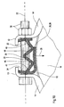
- Figure 10 shows a schematic representation of the support element according to the figures 6 to 9 in an assembled state.
- a brake chamber which consists of two housing halves is formed, of which only the first housing half 16 can be seen in FIG is.
- the first housing half 16 can be designed as shown in FIG. 4 be and has a first collar 62.
- the clamping ring 14 has a first eyelet 10 and a second eyelet 12. Between the first eyelet 10 and the second eyelet 12 the support element explained with reference to FIGS. 6 to 9 is arranged.
- FIGS. 11 and 12 show a second embodiment of the invention Support element shown, which is designed in two pieces in this case.
- Figure 11 shows a side view
- Figure 12 is a front view.
- the first section 24 is formed by a first part 48
- the second section 26 is formed by a second part 50.
- the first part 48 points a first bore 32 which is provided, one through the eyelets one Take up the clamping ring guided screw.
- the based on the representation of 11 central region of the first part 48 or of the first section 24 has an eccentricity 52.
- the eccentricity 52 is in the manner of a Nut formed portion of an outer peripheral portion 56 of the first portion 24 formed.
- Figure 13 shows a schematic representation of the support element according to the figures 11 and 12 in an assembled state.
- an only partially shown clamping ring 14 placed around a brake chamber by two housing halves is formed, of which only the first housing half in Figure 13 16 can be seen.
- the clamping ring 14 again has a first eyelet 10 and a second one Eyelet 12 on. Between the first eyelet 10 and the second eyelet 12, this is based on FIG Figures 11 and 12 explained support element arranged.
- Include connecting means 38 a screw and a nut, the screw passing through the first eyelet 10, that provided in the first part 48 or the first section 24 first bore 32 and the second eyelet 12 is guided.
Landscapes
- Engineering & Computer Science (AREA)
- General Engineering & Computer Science (AREA)
- Mechanical Engineering (AREA)
- Transportation (AREA)
- Clamps And Clips (AREA)
- Connection Of Plates (AREA)
- Insulation, Fastening Of Motor, Generator Windings (AREA)
- Gyroscopes (AREA)
- Discharging, Photosensitive Material Shape In Electrophotography (AREA)
- Braking Arrangements (AREA)
Abstract
Description
- Figur 1
- eine Seitenansicht eines Abstützelementes gemäß dem Stand der Technik;
- Figur 2
- eine Vorderansicht des Abstützelementes gemäß Figur 1;
- Figur 3
- eine Draufsicht des Abstützelementes gemäß Figur 1;
- Figur 4
- eine Ausführungsform einer durch zwei Gehäusehälften gebildeten Bremskammer;
- Figur 5
- die Gehäusehälften gemäß Figur 4 in einem durch einen Spannring verbundenen Zustand;
- Figur 6
- eine perspektivische Darstellung einer ersten Ausführungsform des erfindungsgemäßen Abstützelements;
- Figur 7
- eine Draufsicht des Abstützelements gemäß Figur 6;
- Figur 8
- eine Seitenansicht des Abstützelements gemäß Figur 6;
- Figur 9
- eine Vorderansicht des Abstützelements gemäß Figur 6;
- Figur 10
- eine schematische Darstellung des Abstützelements gemäß den Figuren 6 bis 9 in einem montierten Zustand;
- Figur 11
- eine Seitenansicht einer zweiten Ausführungsform des erfindungsgemäßen Abstützelementes, bei dem der erste Abschnitt und der zweite Abschnitt durch getrennte Teile gebildet sind;
- Figur 12
- eine Vorderansicht des Abstützelementes gemäß Figur 11; und
- Figur 13
- eine schematische Darstellung des Abstützelements gemäß den Figuren 11 und 12 in einem montierten Zustand.
Claims (16)
- Abstützelement, das dazu vorgesehen ist, zumindest abschnittsweise zwischen zwei Ösen (10, 12) eines Spannrings (14) angeordnet zu werden, insbesondere zwischen zwei Ösen (10, 12) eines zum Verbinden von zwei Gehäusehälften (16, 18) einer Bremskammer vorgesehenen Spannrings, um eine Kraft in einer ersten Kraftrichtung (28) auf einen Gegenstand (20), insbesondere eine Bremskammer, auszuüben, die im Wesentlichen senkrecht zu einer die Ösen (10, 12) verbindenden Geraden (22) orientiert ist, dadurch gekennzeichnet, dass das Abstützelement einen ersten Abschnitt (24) und einen bezüglich diesem beweglichen zweiten Abschnitt (26) aufweist, der die Kraft in der ersten Kraftrichtung (28) auf den Gegenstand (20) überträgt.
- Abstützelement nach Anspruch 1, dadurch gekennzeichnet, dass das Abstützelement einstückig ausgebildet und zumindest abschnittsweise verformbar, insbesondere elastisch verformbar ist.
- Abstützelement nach Anspruch 1 oder 2, dadurch gekennzeichnet, dass der zweite Abschnitt (26) durch eine Zunge (30) gebildet ist, die derart an dem ersten Abschnitt (24) befestigt ist, dass sie bei einer in Richtung der Geraden (22) erfolgenden Verformung des ersten Abschnitts (24) auf den Gegenstand (20) gedrückt wird.
- Abstützelement nach einem der vorhergehenden Ansprüche, dadurch gekennzeichnet, dass es zumindest eine erste Bohrung (32) aufweist, die dazu vorgesehen ist, ein durch zumindest eine Öse (10, 12) geführtes Verbindungsmittel (38) aufzunehmen.
- Abstützelement nach einem der vorhergehenden Ansprüche, dadurch gekennzeichnet, dass der erste Abschnitt (24) im Wesentlichen W-förmig ausgebildet ist.
- Abstützelement nach Anspruch 5, dadurch gekennzeichnet, dass in dem ersten freien Schenkel (40) des im Wesentlichen W-förmigen ersten Abschnitts (24) eine erste Bohrung (32) und in dem zweiten freien Schenkel (42) des im Wesentlichen W-förmigen Abschnitts eine zweite Bohrung (34) vorgesehen ist.
- Abstützelement nach Anspruch 5 oder 6, dadurch gekennzeichnet, dass der zweite Abschnitt (26) an einem freien Schenkel (42) des im Wesentlichen W-förmigen ersten Abschnitts (24) befestigt ist.
- Abstützelement nach einem der Ansprüche 5 bis 7, dadurch gekennzeichnet, dass zumindest einer der zwischen den freien Schenkeln (40, 42) des im Wesentlichen W-förmigen ersten Abschnitts (24) vorgesehenen Schenkel (44, 46b) eine Ausnehmung (36) aufweist.
- Abstützelement nach Anspruch 1 oder einem der Ansprüche 3 bis 8, dadurch gekennzeichnet, dass der erste Abschnitt (24) und der zweite Abschnitt (26) durch getrennte Teile gebildet sind.
- Abstützelement nach einem der vorhergehenden Ansprüche, dadurch gekennzeichnet, dass der erste Abschnitt (24) eine Exzentrizität (52) aufweist und um eine Drehachse (54) drehbar ist.
- Abstützelement nach Anspruch 10, dadurch gekennzeichnet, dass die Drehachse (54) im Wesentlichen parallel zu Geraden (22) ist.
- Abstützelement nach Anspruch 10 oder 11, dadurch gekennzeichnet, dass der erste Abschnitt (24) in seinem Außenumfangsbereich (56) zumindest abschnittsweise nach Art einer Mutter ausgebildet ist.
- Abstützelement nach einem der vorhergehenden Ansprüche, dadurch gekennzeichnet, dass es zumindest teilweise aus Kunststoff gebildet ist.
- Abstützelement nach Anspruch 13, dadurch gekennzeichnet, dass der Kunststoff Polypropylen ist.
- Abstützelement nach einem der vorhergehenden Ansprüche, dadurch gekennzeichnet, dass der zweite Abschnitt (26) zumindest einen Steg (58, 60) aufweist, der dazu vorgesehen ist, einen Kragen (62, 64) des Gegenstandes zu umgreifen.
- Abstützelement nach einem der vorhergehenden Ansprüche, dadurch gekennzeichnet, dass ein erster Steg (58) eine im Wesentlichen senkrecht zur Geraden (22) und senkrecht zur ersten Kraftrichtung (28) orientierte Kraftkomponente in einer zweiten Kraftrichtung (66) auf den Gegenstand (20) ausübt und/oder dass ein zweiter Steg (60) eine im Wesentlichen senkrecht zur Geraden (22) und senkrecht zur ersten Kraftrichtung (28) orientierte Kraftkomponente in einer dritten Kraftrichtung (68) auf den Gegenstand (20) ausübt.
Applications Claiming Priority (2)
| Application Number | Priority Date | Filing Date | Title |
|---|---|---|---|
| DE10153029 | 2001-10-26 | ||
| DE10153029A DE10153029A1 (de) | 2001-10-26 | 2001-10-26 | Abstützelement |
Publications (2)
| Publication Number | Publication Date |
|---|---|
| EP1306280A1 true EP1306280A1 (de) | 2003-05-02 |
| EP1306280B1 EP1306280B1 (de) | 2005-09-07 |
Family
ID=7703899
Family Applications (1)
| Application Number | Title | Priority Date | Filing Date |
|---|---|---|---|
| EP02022985A Expired - Lifetime EP1306280B1 (de) | 2001-10-26 | 2002-10-14 | Abstützelement bei einem Spannring |
Country Status (3)
| Country | Link |
|---|---|
| EP (1) | EP1306280B1 (de) |
| AT (1) | ATE303925T1 (de) |
| DE (2) | DE10153029A1 (de) |
Cited By (1)
| Publication number | Priority date | Publication date | Assignee | Title |
|---|---|---|---|---|
| EP1588917A1 (de) * | 2004-04-21 | 2005-10-26 | KNORR-BREMSE SYSTEME FÜR NUTZFAHRZEUGE GmbH | Befestigungsklemme für Bremszylinder |
Citations (4)
| Publication number | Priority date | Publication date | Assignee | Title |
|---|---|---|---|---|
| US3087220A (en) * | 1960-09-15 | 1963-04-30 | Page Mfg Company Du | Worm drive hose clamp |
| US4109350A (en) * | 1976-10-07 | 1978-08-29 | Midland-Ross Corporation | Clamp band |
| GB1589038A (en) * | 1977-08-11 | 1981-05-07 | Bosch Gmbh Robert | Clamping rings |
| US5775202A (en) * | 1996-06-25 | 1998-07-07 | Indian Head Industries, Inc. | Deformed clamp band made from continuous roll |
Family Cites Families (7)
| Publication number | Priority date | Publication date | Assignee | Title |
|---|---|---|---|---|
| DE8404035U1 (de) * | 1984-06-07 | Knorr-Bremse GmbH, 8000 München | Spannband für das Gehäuse von Membranzylindern, insbesondere für Bremszylinder von Kraftfahrzeugen | |
| DE2230991B2 (de) * | 1972-06-24 | 1975-12-18 | Wabco Westinghouse Gmbh, 3000 Hannover | Spannband |
| FR2538072B1 (fr) * | 1982-12-20 | 1986-05-02 | Pont A Mousson | Collier de serrage pour joint d'etancheite a manchon pour canalisations |
| DE3445270A1 (de) * | 1984-12-12 | 1986-06-19 | Mengering Sanitär-Haustechnik GmbH, 8700 Würzburg | Vorrichtung zum abgedichteten verbinden der glattzylindrischen enden zweier rohre |
| FR2662486B1 (fr) * | 1990-05-23 | 1992-09-11 | Caillau Ets | Dispositif d'accouplement etanche de deux tubes lisses, disposes bout a bout. |
| GB2310903B (en) * | 1996-03-05 | 1999-12-15 | Avk Mfg Ltd | A pipe repair or jointing collar |
| SE508749C2 (sv) * | 1996-12-20 | 1998-11-02 | Lindab Ab | Sätt att hopkoppla två rör |
-
2001
- 2001-10-26 DE DE10153029A patent/DE10153029A1/de not_active Withdrawn
-
2002
- 2002-10-14 EP EP02022985A patent/EP1306280B1/de not_active Expired - Lifetime
- 2002-10-14 DE DE50204158T patent/DE50204158D1/de not_active Expired - Lifetime
- 2002-10-14 AT AT02022985T patent/ATE303925T1/de not_active IP Right Cessation
Patent Citations (4)
| Publication number | Priority date | Publication date | Assignee | Title |
|---|---|---|---|---|
| US3087220A (en) * | 1960-09-15 | 1963-04-30 | Page Mfg Company Du | Worm drive hose clamp |
| US4109350A (en) * | 1976-10-07 | 1978-08-29 | Midland-Ross Corporation | Clamp band |
| GB1589038A (en) * | 1977-08-11 | 1981-05-07 | Bosch Gmbh Robert | Clamping rings |
| US5775202A (en) * | 1996-06-25 | 1998-07-07 | Indian Head Industries, Inc. | Deformed clamp band made from continuous roll |
Cited By (1)
| Publication number | Priority date | Publication date | Assignee | Title |
|---|---|---|---|---|
| EP1588917A1 (de) * | 2004-04-21 | 2005-10-26 | KNORR-BREMSE SYSTEME FÜR NUTZFAHRZEUGE GmbH | Befestigungsklemme für Bremszylinder |
Also Published As
| Publication number | Publication date |
|---|---|
| DE50204158D1 (de) | 2005-10-13 |
| DE10153029A1 (de) | 2003-05-22 |
| ATE303925T1 (de) | 2005-09-15 |
| EP1306280B1 (de) | 2005-09-07 |
Similar Documents
| Publication | Publication Date | Title |
|---|---|---|
| DE2335119C3 (de) | Rohrkupplung | |
| DE19621746B4 (de) | Vorrichtung zur Herstellung einer Verbindung zwischen zwei Bauteilen | |
| DE2732048A1 (de) | Befestigungsvorrichtung | |
| EP0550813A1 (de) | Rohrkupplung | |
| DE1907519A1 (de) | Mutter mit mehreren Abdrehbuenden | |
| DE2502263A1 (de) | Anordnung zur klemmverbindung mindestens zweier rohre | |
| DE69417852T2 (de) | Klemmschelle mit sägzahnförmiger Verschlussanordnung | |
| EP0175856A2 (de) | Spannmuffe mit einer Spannschraube | |
| DE69724392T2 (de) | Verfahren zum Verbinden von Rohren | |
| DE4210456A1 (de) | Querverbindung für Profilstäbe mittels Zuggliedern | |
| EP1396644A1 (de) | Vorrichtung zum Verbinden von Montageschienen | |
| DE60212270T2 (de) | Verbindungsmuffe mit in axialer Richtung zusammengedrückter Dichtring | |
| AT395203B (de) | Verbindungselement fuer den stirnseitigen anschluss eines rohres an ein kugelfoermiges bauteil | |
| DE10324236A1 (de) | Haltevorrichtung für ein Schlauchende | |
| DE2708538A1 (de) | Verbindung zwischen den kettengliedern einer gleiskette | |
| DE9420832U1 (de) | Querverbindung für Profilstäbe | |
| DE3346067C2 (de) | ||
| EP1306280B1 (de) | Abstützelement bei einem Spannring | |
| WO2001038747A1 (de) | Mutter mit druckring | |
| DE19903972A1 (de) | Mutter zur Schnellbefestigung | |
| DE19757751A1 (de) | Dichtungsvorrichtung zum abdichtenden Durchführen mindestens einer Leitung@ | |
| DE10304514B4 (de) | Fixierteil für eine Schlauchschelle | |
| DE69909666T2 (de) | Vorrichtung zum Verbinden des Ankerkerns eines elastischen Gelenks mit einem Aussenteil | |
| DE69121548T2 (de) | Verbesserte Bandschelle mit keilförmigen, geschlitzten Nocken | |
| EP2082144A1 (de) | Kombination aus einer schraube und einer hülse sowie verfahren zum herstellen einer solchen kombination |
Legal Events
| Date | Code | Title | Description |
|---|---|---|---|
| PUAI | Public reference made under article 153(3) epc to a published international application that has entered the european phase |
Free format text: ORIGINAL CODE: 0009012 |
|
| AK | Designated contracting states |
Designated state(s): AT BE BG CH CY CZ DE DK EE ES FI FR GB GR IE IT LI LU MC NL PT SE SK TR |
|
| AX | Request for extension of the european patent |
Extension state: AL LT LV MK RO SI |
|
| 17P | Request for examination filed |
Effective date: 20031103 |
|
| AKX | Designation fees paid |
Designated state(s): AT BE BG CH CY CZ DE DK EE ES FI FR GB GR IE IT LI LU MC NL PT SE SK TR |
|
| 17Q | First examination report despatched |
Effective date: 20040205 |
|
| GRAP | Despatch of communication of intention to grant a patent |
Free format text: ORIGINAL CODE: EPIDOSNIGR1 |
|
| GRAS | Grant fee paid |
Free format text: ORIGINAL CODE: EPIDOSNIGR3 |
|
| GRAA | (expected) grant |
Free format text: ORIGINAL CODE: 0009210 |
|
| AK | Designated contracting states |
Kind code of ref document: B1 Designated state(s): AT BE BG CH CY CZ DE DK EE ES FI FR GB GR IE IT LI LU MC NL PT SE SK TR |
|
| PG25 | Lapsed in a contracting state [announced via postgrant information from national office to epo] |
Ref country code: EE Free format text: LAPSE BECAUSE OF FAILURE TO SUBMIT A TRANSLATION OF THE DESCRIPTION OR TO PAY THE FEE WITHIN THE PRESCRIBED TIME-LIMIT Effective date: 20050907 Ref country code: SK Free format text: LAPSE BECAUSE OF FAILURE TO SUBMIT A TRANSLATION OF THE DESCRIPTION OR TO PAY THE FEE WITHIN THE PRESCRIBED TIME-LIMIT Effective date: 20050907 Ref country code: IE Free format text: LAPSE BECAUSE OF FAILURE TO SUBMIT A TRANSLATION OF THE DESCRIPTION OR TO PAY THE FEE WITHIN THE PRESCRIBED TIME-LIMIT Effective date: 20050907 Ref country code: FI Free format text: LAPSE BECAUSE OF FAILURE TO SUBMIT A TRANSLATION OF THE DESCRIPTION OR TO PAY THE FEE WITHIN THE PRESCRIBED TIME-LIMIT Effective date: 20050907 Ref country code: CZ Free format text: LAPSE BECAUSE OF FAILURE TO SUBMIT A TRANSLATION OF THE DESCRIPTION OR TO PAY THE FEE WITHIN THE PRESCRIBED TIME-LIMIT Effective date: 20050907 Ref country code: NL Free format text: LAPSE BECAUSE OF FAILURE TO SUBMIT A TRANSLATION OF THE DESCRIPTION OR TO PAY THE FEE WITHIN THE PRESCRIBED TIME-LIMIT Effective date: 20050907 |
|
| REG | Reference to a national code |
Ref country code: GB Ref legal event code: FG4D Free format text: NOT ENGLISH |
|
| RIN1 | Information on inventor provided before grant (corrected) |
Inventor name: SOMMER, PETR |
|
| REG | Reference to a national code |
Ref country code: CH Ref legal event code: EP |
|
| REG | Reference to a national code |
Ref country code: IE Ref legal event code: FG4D Free format text: LANGUAGE OF EP DOCUMENT: GERMAN |
|
| REF | Corresponds to: |
Ref document number: 50204158 Country of ref document: DE Date of ref document: 20051013 Kind code of ref document: P |
|
| PG25 | Lapsed in a contracting state [announced via postgrant information from national office to epo] |
Ref country code: CY Free format text: LAPSE BECAUSE OF FAILURE TO SUBMIT A TRANSLATION OF THE DESCRIPTION OR TO PAY THE FEE WITHIN THE PRESCRIBED TIME-LIMIT Effective date: 20051014 Ref country code: AT Free format text: LAPSE BECAUSE OF NON-PAYMENT OF DUE FEES Effective date: 20051014 |
|
| REG | Reference to a national code |
Ref country code: SE Ref legal event code: TRGR |
|
| PG25 | Lapsed in a contracting state [announced via postgrant information from national office to epo] |
Ref country code: MC Free format text: LAPSE BECAUSE OF NON-PAYMENT OF DUE FEES Effective date: 20051031 Ref country code: BE Free format text: LAPSE BECAUSE OF NON-PAYMENT OF DUE FEES Effective date: 20051031 |
|
| PG25 | Lapsed in a contracting state [announced via postgrant information from national office to epo] |
Ref country code: LU Free format text: LAPSE BECAUSE OF NON-PAYMENT OF DUE FEES Effective date: 20051107 |
|
| PG25 | Lapsed in a contracting state [announced via postgrant information from national office to epo] |
Ref country code: BG Free format text: LAPSE BECAUSE OF FAILURE TO SUBMIT A TRANSLATION OF THE DESCRIPTION OR TO PAY THE FEE WITHIN THE PRESCRIBED TIME-LIMIT Effective date: 20051207 Ref country code: GR Free format text: LAPSE BECAUSE OF FAILURE TO SUBMIT A TRANSLATION OF THE DESCRIPTION OR TO PAY THE FEE WITHIN THE PRESCRIBED TIME-LIMIT Effective date: 20051207 Ref country code: DK Free format text: LAPSE BECAUSE OF FAILURE TO SUBMIT A TRANSLATION OF THE DESCRIPTION OR TO PAY THE FEE WITHIN THE PRESCRIBED TIME-LIMIT Effective date: 20051207 |
|
| GBT | Gb: translation of ep patent filed (gb section 77(6)(a)/1977) | ||
| PG25 | Lapsed in a contracting state [announced via postgrant information from national office to epo] |
Ref country code: ES Free format text: LAPSE BECAUSE OF FAILURE TO SUBMIT A TRANSLATION OF THE DESCRIPTION OR TO PAY THE FEE WITHIN THE PRESCRIBED TIME-LIMIT Effective date: 20051218 |
|
| PG25 | Lapsed in a contracting state [announced via postgrant information from national office to epo] |
Ref country code: PT Free format text: LAPSE BECAUSE OF FAILURE TO SUBMIT A TRANSLATION OF THE DESCRIPTION OR TO PAY THE FEE WITHIN THE PRESCRIBED TIME-LIMIT Effective date: 20060207 |
|
| NLV1 | Nl: lapsed or annulled due to failure to fulfill the requirements of art. 29p and 29m of the patents act | ||
| REG | Reference to a national code |
Ref country code: IE Ref legal event code: FD4D |
|
| ET | Fr: translation filed | ||
| PLBE | No opposition filed within time limit |
Free format text: ORIGINAL CODE: 0009261 |
|
| STAA | Information on the status of an ep patent application or granted ep patent |
Free format text: STATUS: NO OPPOSITION FILED WITHIN TIME LIMIT |
|
| 26N | No opposition filed |
Effective date: 20060608 |
|
| PG25 | Lapsed in a contracting state [announced via postgrant information from national office to epo] |
Ref country code: LI Free format text: LAPSE BECAUSE OF NON-PAYMENT OF DUE FEES Effective date: 20061031 Ref country code: CH Free format text: LAPSE BECAUSE OF NON-PAYMENT OF DUE FEES Effective date: 20061031 |
|
| REG | Reference to a national code |
Ref country code: CH Ref legal event code: PL |
|
| BERE | Be: lapsed |
Owner name: KNORR-BREMSE SYSTEME FUR NUTZFAHRZEUGE G.M.B.H. Effective date: 20051031 |
|
| REG | Reference to a national code |
Ref country code: FR Ref legal event code: PLFP Year of fee payment: 14 |
|
| REG | Reference to a national code |
Ref country code: FR Ref legal event code: PLFP Year of fee payment: 15 |
|
| PGFP | Annual fee paid to national office [announced via postgrant information from national office to epo] |
Ref country code: GB Payment date: 20161025 Year of fee payment: 15 |
|
| PGFP | Annual fee paid to national office [announced via postgrant information from national office to epo] |
Ref country code: SE Payment date: 20161025 Year of fee payment: 15 Ref country code: IT Payment date: 20161025 Year of fee payment: 15 |
|
| PGFP | Annual fee paid to national office [announced via postgrant information from national office to epo] |
Ref country code: TR Payment date: 20161005 Year of fee payment: 15 |
|
| REG | Reference to a national code |
Ref country code: FR Ref legal event code: PLFP Year of fee payment: 16 |
|
| REG | Reference to a national code |
Ref country code: SE Ref legal event code: EUG |
|
| GBPC | Gb: european patent ceased through non-payment of renewal fee |
Effective date: 20171014 |
|
| PG25 | Lapsed in a contracting state [announced via postgrant information from national office to epo] |
Ref country code: GB Free format text: LAPSE BECAUSE OF NON-PAYMENT OF DUE FEES Effective date: 20171014 |
|
| PG25 | Lapsed in a contracting state [announced via postgrant information from national office to epo] |
Ref country code: SE Free format text: LAPSE BECAUSE OF NON-PAYMENT OF DUE FEES Effective date: 20171015 |
|
| REG | Reference to a national code |
Ref country code: FR Ref legal event code: PLFP Year of fee payment: 17 |
|
| PG25 | Lapsed in a contracting state [announced via postgrant information from national office to epo] |
Ref country code: IT Free format text: LAPSE BECAUSE OF NON-PAYMENT OF DUE FEES Effective date: 20171014 |
|
| PGFP | Annual fee paid to national office [announced via postgrant information from national office to epo] |
Ref country code: DE Payment date: 20191023 Year of fee payment: 18 |
|
| PGFP | Annual fee paid to national office [announced via postgrant information from national office to epo] |
Ref country code: FR Payment date: 20191022 Year of fee payment: 18 |
|
| REG | Reference to a national code |
Ref country code: DE Ref legal event code: R119 Ref document number: 50204158 Country of ref document: DE |
|
| PG25 | Lapsed in a contracting state [announced via postgrant information from national office to epo] |
Ref country code: FR Free format text: LAPSE BECAUSE OF NON-PAYMENT OF DUE FEES Effective date: 20201031 Ref country code: DE Free format text: LAPSE BECAUSE OF NON-PAYMENT OF DUE FEES Effective date: 20210501 |
|
| PG25 | Lapsed in a contracting state [announced via postgrant information from national office to epo] |
Ref country code: TR Free format text: LAPSE BECAUSE OF FAILURE TO SUBMIT A TRANSLATION OF THE DESCRIPTION OR TO PAY THE FEE WITHIN THE PRESCRIBED TIME-LIMIT Effective date: 20050907 |