EP1306195A2 - Procédé et dispositif pour la commande d'une opération de soufflage - Google Patents
Procédé et dispositif pour la commande d'une opération de soufflage Download PDFInfo
- Publication number
- EP1306195A2 EP1306195A2 EP02018446A EP02018446A EP1306195A2 EP 1306195 A2 EP1306195 A2 EP 1306195A2 EP 02018446 A EP02018446 A EP 02018446A EP 02018446 A EP02018446 A EP 02018446A EP 1306195 A2 EP1306195 A2 EP 1306195A2
- Authority
- EP
- European Patent Office
- Prior art keywords
- blowing
- central machine
- evaluation unit
- control
- valves
- Prior art date
- Legal status (The legal status is an assumption and is not a legal conclusion. Google has not performed a legal analysis and makes no representation as to the accuracy of the status listed.)
- Granted
Links
- 238000000034 method Methods 0.000 title claims description 32
- 230000008569 process Effects 0.000 title claims description 16
- 238000005259 measurement Methods 0.000 claims abstract description 11
- 238000012545 processing Methods 0.000 claims abstract description 11
- 238000007664 blowing Methods 0.000 claims description 72
- 238000011156 evaluation Methods 0.000 claims description 37
- 238000010438 heat treatment Methods 0.000 claims description 20
- 230000005540 biological transmission Effects 0.000 claims description 10
- 238000000071 blow moulding Methods 0.000 claims description 10
- 238000004519 manufacturing process Methods 0.000 claims description 10
- 238000012800 visualization Methods 0.000 claims description 8
- 230000001934 delay Effects 0.000 claims description 7
- 230000004044 response Effects 0.000 claims description 6
- 230000008878 coupling Effects 0.000 claims description 5
- 238000010168 coupling process Methods 0.000 claims description 5
- 238000005859 coupling reaction Methods 0.000 claims description 5
- 238000001514 detection method Methods 0.000 claims description 5
- 239000012530 fluid Substances 0.000 claims description 5
- 230000006870 function Effects 0.000 claims description 5
- 230000006978 adaptation Effects 0.000 claims description 4
- 230000001419 dependent effect Effects 0.000 claims description 2
- 229920001169 thermoplastic Polymers 0.000 claims description 2
- 239000004416 thermosoftening plastic Substances 0.000 claims description 2
- 238000001816 cooling Methods 0.000 description 8
- 238000010586 diagram Methods 0.000 description 8
- 238000012546 transfer Methods 0.000 description 7
- 239000000463 material Substances 0.000 description 4
- 229920000139 polyethylene terephthalate Polymers 0.000 description 4
- 239000005020 polyethylene terephthalate Substances 0.000 description 4
- 230000008859 change Effects 0.000 description 3
- 238000009826 distribution Methods 0.000 description 3
- 238000000465 moulding Methods 0.000 description 3
- 238000010276 construction Methods 0.000 description 2
- 239000000498 cooling water Substances 0.000 description 2
- 238000012937 correction Methods 0.000 description 2
- 238000013461 design Methods 0.000 description 2
- 238000001746 injection moulding Methods 0.000 description 2
- -1 polyethylene terephthalate Polymers 0.000 description 2
- 239000012815 thermoplastic material Substances 0.000 description 2
- 230000004913 activation Effects 0.000 description 1
- 230000000712 assembly Effects 0.000 description 1
- 238000000429 assembly Methods 0.000 description 1
- 230000006399 behavior Effects 0.000 description 1
- 230000009286 beneficial effect Effects 0.000 description 1
- 230000015572 biosynthetic process Effects 0.000 description 1
- 239000000969 carrier Substances 0.000 description 1
- 239000003795 chemical substances by application Substances 0.000 description 1
- 230000001143 conditioned effect Effects 0.000 description 1
- 125000004122 cyclic group Chemical group 0.000 description 1
- 238000009795 derivation Methods 0.000 description 1
- 230000000694 effects Effects 0.000 description 1
- 238000005516 engineering process Methods 0.000 description 1
- 235000013305 food Nutrition 0.000 description 1
- 238000003780 insertion Methods 0.000 description 1
- 230000037431 insertion Effects 0.000 description 1
- 230000003993 interaction Effects 0.000 description 1
- 238000012544 monitoring process Methods 0.000 description 1
- 230000005693 optoelectronics Effects 0.000 description 1
- 239000004033 plastic Substances 0.000 description 1
- 229920003023 plastic Polymers 0.000 description 1
- 230000005855 radiation Effects 0.000 description 1
- 238000004171 remote diagnosis Methods 0.000 description 1
- 239000007787 solid Substances 0.000 description 1
- 238000007711 solidification Methods 0.000 description 1
- 230000008023 solidification Effects 0.000 description 1
- 238000003860 storage Methods 0.000 description 1
- 238000005496 tempering Methods 0.000 description 1
- 230000002123 temporal effect Effects 0.000 description 1
- 230000007704 transition Effects 0.000 description 1
Images


Classifications
-
- B—PERFORMING OPERATIONS; TRANSPORTING
- B29—WORKING OF PLASTICS; WORKING OF SUBSTANCES IN A PLASTIC STATE IN GENERAL
- B29C—SHAPING OR JOINING OF PLASTICS; SHAPING OF MATERIAL IN A PLASTIC STATE, NOT OTHERWISE PROVIDED FOR; AFTER-TREATMENT OF THE SHAPED PRODUCTS, e.g. REPAIRING
- B29C49/00—Blow-moulding, i.e. blowing a preform or parison to a desired shape within a mould; Apparatus therefor
- B29C49/42—Component parts, details or accessories; Auxiliary operations
- B29C49/78—Measuring, controlling or regulating
-
- B—PERFORMING OPERATIONS; TRANSPORTING
- B29—WORKING OF PLASTICS; WORKING OF SUBSTANCES IN A PLASTIC STATE IN GENERAL
- B29C—SHAPING OR JOINING OF PLASTICS; SHAPING OF MATERIAL IN A PLASTIC STATE, NOT OTHERWISE PROVIDED FOR; AFTER-TREATMENT OF THE SHAPED PRODUCTS, e.g. REPAIRING
- B29C35/00—Heating, cooling or curing, e.g. crosslinking or vulcanising; Apparatus therefor
- B29C35/02—Heating or curing, e.g. crosslinking or vulcanizing during moulding, e.g. in a mould
- B29C35/08—Heating or curing, e.g. crosslinking or vulcanizing during moulding, e.g. in a mould by wave energy or particle radiation
- B29C35/0805—Heating or curing, e.g. crosslinking or vulcanizing during moulding, e.g. in a mould by wave energy or particle radiation using electromagnetic radiation
- B29C2035/0822—Heating or curing, e.g. crosslinking or vulcanizing during moulding, e.g. in a mould by wave energy or particle radiation using electromagnetic radiation using IR radiation
-
- B—PERFORMING OPERATIONS; TRANSPORTING
- B29—WORKING OF PLASTICS; WORKING OF SUBSTANCES IN A PLASTIC STATE IN GENERAL
- B29C—SHAPING OR JOINING OF PLASTICS; SHAPING OF MATERIAL IN A PLASTIC STATE, NOT OTHERWISE PROVIDED FOR; AFTER-TREATMENT OF THE SHAPED PRODUCTS, e.g. REPAIRING
- B29C35/00—Heating, cooling or curing, e.g. crosslinking or vulcanising; Apparatus therefor
- B29C35/02—Heating or curing, e.g. crosslinking or vulcanizing during moulding, e.g. in a mould
- B29C35/08—Heating or curing, e.g. crosslinking or vulcanizing during moulding, e.g. in a mould by wave energy or particle radiation
- B29C35/0805—Heating or curing, e.g. crosslinking or vulcanizing during moulding, e.g. in a mould by wave energy or particle radiation using electromagnetic radiation
- B29C2035/0855—Heating or curing, e.g. crosslinking or vulcanizing during moulding, e.g. in a mould by wave energy or particle radiation using electromagnetic radiation using microwave
-
- B—PERFORMING OPERATIONS; TRANSPORTING
- B29—WORKING OF PLASTICS; WORKING OF SUBSTANCES IN A PLASTIC STATE IN GENERAL
- B29C—SHAPING OR JOINING OF PLASTICS; SHAPING OF MATERIAL IN A PLASTIC STATE, NOT OTHERWISE PROVIDED FOR; AFTER-TREATMENT OF THE SHAPED PRODUCTS, e.g. REPAIRING
- B29C49/00—Blow-moulding, i.e. blowing a preform or parison to a desired shape within a mould; Apparatus therefor
- B29C49/42—Component parts, details or accessories; Auxiliary operations
- B29C49/78—Measuring, controlling or regulating
- B29C49/783—Measuring, controlling or regulating blowing pressure
- B29C2049/7832—Blowing with two or more pressure levels
-
- B—PERFORMING OPERATIONS; TRANSPORTING
- B29—WORKING OF PLASTICS; WORKING OF SUBSTANCES IN A PLASTIC STATE IN GENERAL
- B29C—SHAPING OR JOINING OF PLASTICS; SHAPING OF MATERIAL IN A PLASTIC STATE, NOT OTHERWISE PROVIDED FOR; AFTER-TREATMENT OF THE SHAPED PRODUCTS, e.g. REPAIRING
- B29C49/00—Blow-moulding, i.e. blowing a preform or parison to a desired shape within a mould; Apparatus therefor
- B29C49/42—Component parts, details or accessories; Auxiliary operations
- B29C49/78—Measuring, controlling or regulating
- B29C2049/788—Controller type or interface
- B29C2049/78805—Computer or PLC control
-
- B—PERFORMING OPERATIONS; TRANSPORTING
- B29—WORKING OF PLASTICS; WORKING OF SUBSTANCES IN A PLASTIC STATE IN GENERAL
- B29C—SHAPING OR JOINING OF PLASTICS; SHAPING OF MATERIAL IN A PLASTIC STATE, NOT OTHERWISE PROVIDED FOR; AFTER-TREATMENT OF THE SHAPED PRODUCTS, e.g. REPAIRING
- B29C2949/00—Indexing scheme relating to blow-moulding
- B29C2949/07—Preforms or parisons characterised by their configuration
- B29C2949/0715—Preforms or parisons characterised by their configuration the preform having one end closed
-
- B—PERFORMING OPERATIONS; TRANSPORTING
- B29—WORKING OF PLASTICS; WORKING OF SUBSTANCES IN A PLASTIC STATE IN GENERAL
- B29C—SHAPING OR JOINING OF PLASTICS; SHAPING OF MATERIAL IN A PLASTIC STATE, NOT OTHERWISE PROVIDED FOR; AFTER-TREATMENT OF THE SHAPED PRODUCTS, e.g. REPAIRING
- B29C49/00—Blow-moulding, i.e. blowing a preform or parison to a desired shape within a mould; Apparatus therefor
- B29C49/02—Combined blow-moulding and manufacture of the preform or the parison
- B29C49/06—Injection blow-moulding
-
- B—PERFORMING OPERATIONS; TRANSPORTING
- B29—WORKING OF PLASTICS; WORKING OF SUBSTANCES IN A PLASTIC STATE IN GENERAL
- B29C—SHAPING OR JOINING OF PLASTICS; SHAPING OF MATERIAL IN A PLASTIC STATE, NOT OTHERWISE PROVIDED FOR; AFTER-TREATMENT OF THE SHAPED PRODUCTS, e.g. REPAIRING
- B29C49/00—Blow-moulding, i.e. blowing a preform or parison to a desired shape within a mould; Apparatus therefor
- B29C49/08—Biaxial stretching during blow-moulding
- B29C49/10—Biaxial stretching during blow-moulding using mechanical means for prestretching
- B29C49/12—Stretching rods
-
- B—PERFORMING OPERATIONS; TRANSPORTING
- B29—WORKING OF PLASTICS; WORKING OF SUBSTANCES IN A PLASTIC STATE IN GENERAL
- B29C—SHAPING OR JOINING OF PLASTICS; SHAPING OF MATERIAL IN A PLASTIC STATE, NOT OTHERWISE PROVIDED FOR; AFTER-TREATMENT OF THE SHAPED PRODUCTS, e.g. REPAIRING
- B29C49/00—Blow-moulding, i.e. blowing a preform or parison to a desired shape within a mould; Apparatus therefor
- B29C49/08—Biaxial stretching during blow-moulding
- B29C49/10—Biaxial stretching during blow-moulding using mechanical means for prestretching
- B29C49/122—Drive means therefor
- B29C49/1229—Drive means therefor being a cam mechanism
-
- B—PERFORMING OPERATIONS; TRANSPORTING
- B29—WORKING OF PLASTICS; WORKING OF SUBSTANCES IN A PLASTIC STATE IN GENERAL
- B29C—SHAPING OR JOINING OF PLASTICS; SHAPING OF MATERIAL IN A PLASTIC STATE, NOT OTHERWISE PROVIDED FOR; AFTER-TREATMENT OF THE SHAPED PRODUCTS, e.g. REPAIRING
- B29C49/00—Blow-moulding, i.e. blowing a preform or parison to a desired shape within a mould; Apparatus therefor
- B29C49/28—Blow-moulding apparatus
- B29C49/30—Blow-moulding apparatus having movable moulds or mould parts
- B29C49/36—Blow-moulding apparatus having movable moulds or mould parts rotatable about one axis
-
- B—PERFORMING OPERATIONS; TRANSPORTING
- B29—WORKING OF PLASTICS; WORKING OF SUBSTANCES IN A PLASTIC STATE IN GENERAL
- B29C—SHAPING OR JOINING OF PLASTICS; SHAPING OF MATERIAL IN A PLASTIC STATE, NOT OTHERWISE PROVIDED FOR; AFTER-TREATMENT OF THE SHAPED PRODUCTS, e.g. REPAIRING
- B29C49/00—Blow-moulding, i.e. blowing a preform or parison to a desired shape within a mould; Apparatus therefor
- B29C49/42—Component parts, details or accessories; Auxiliary operations
- B29C49/4289—Valve constructions or configurations, e.g. arranged to reduce blowing fluid consumption
-
- B—PERFORMING OPERATIONS; TRANSPORTING
- B29—WORKING OF PLASTICS; WORKING OF SUBSTANCES IN A PLASTIC STATE IN GENERAL
- B29C—SHAPING OR JOINING OF PLASTICS; SHAPING OF MATERIAL IN A PLASTIC STATE, NOT OTHERWISE PROVIDED FOR; AFTER-TREATMENT OF THE SHAPED PRODUCTS, e.g. REPAIRING
- B29C49/00—Blow-moulding, i.e. blowing a preform or parison to a desired shape within a mould; Apparatus therefor
- B29C49/42—Component parts, details or accessories; Auxiliary operations
- B29C49/64—Heating or cooling preforms, parisons or blown articles
- B29C49/68—Ovens specially adapted for heating preforms or parisons
- B29C49/6835—Ovens specially adapted for heating preforms or parisons using reflectors
-
- B—PERFORMING OPERATIONS; TRANSPORTING
- B29—WORKING OF PLASTICS; WORKING OF SUBSTANCES IN A PLASTIC STATE IN GENERAL
- B29K—INDEXING SCHEME ASSOCIATED WITH SUBCLASSES B29B, B29C OR B29D, RELATING TO MOULDING MATERIALS OR TO MATERIALS FOR MOULDS, REINFORCEMENTS, FILLERS OR PREFORMED PARTS, e.g. INSERTS
- B29K2067/00—Use of polyesters or derivatives thereof, as moulding material
Definitions
- the invention relates to a method for controlling a Blowing process, in which on a rotating blowing wheel arranged blowing stations for blow molding of thermoplastic preforms in containers at least one pressurized blowing fluid is supplied and in which at least temporarily a current rotational positioning the blowing wheel detected by measurement and the corresponding Information from an evaluation unit with Switching position presets for the supply and discharge of the Blasfluids are compared.
- the invention further relates to a device for Control of a blowing process, the at least one controllable valve, which is in the range of Supply line is arranged for a blowing fluid and in the the supply line a Blasfluid pumps with at least a blowing station that connects on a rotating Blasrad is arranged and with a measured value and with at least one position sensor for detection a rotational positioning of the blowing wheel is provided as well as with the measured value acquisition with a Evaluation unit is connected to the circuit of the valves.
- the at least one controllable valve which is in the range of Supply line is arranged for a blowing fluid and in the the supply line a Blasfluidmakers with at least a blowing station that connects on a rotating Blasrad is arranged and with a measured value and with at least one position sensor for detection a rotational positioning of the blowing wheel is provided as well as with the measured value acquisition with a Evaluation unit is connected to the circuit of the valves.
- Such methods and devices are particularly used in the production of blow-molded containers, coordinated with the execution of the blowing process Supply of one or more blowing pressures and a Derivation of the blowing pressure after a formation of the To perform container.
- the Preforms as well as the blown containers with the help transported different handling equipment become. Has proven particularly the use of Transport mandrels on which the preforms are attached become.
- the preforms can also be used with others Carrying facilities are handled.
- the usage of Tongs for handling preforms and the Use of expanding mandrels for mounting in a Mouth region of the preform are insertable belong also to the available constructions.
- blowing stations With regard to the blowing stations used different embodiments known. at Blowing stations on rotating transport wheels arranged, is a book - like Aufklappbarkeit the Mold carrier frequently encountered. But it is also possible relative to each other displaceable or otherwise guided Insert mold carrier. In blow molding stations, in particular are suitable for several cavities for container molding Also, next to hinged forms are included parallel plates arranged as a mold carrier used.
- Object of the present invention is therefore, a Specify method of the type mentioned in the introduction that achieved an improved control of the valves can be.
- Evaluation unit independent of a processing cycle a central machine control is operated that at least two comparators of the evaluation unit, the Setpoints for the valve control with actual values from the Link measurement information, the measurement information relative be fed to each other in parallel and simultaneously and that the comparators via output stages directly to the Acting valves.
- Another object of the present invention is to provide a Device of the type mentioned in the introduction to such Construct that the production of containers with relative supports mutually identical material distributions becomes.
- the Evaluation unit one of a working cycle one central machine control independent operation has, that the evaluation unit with at least two Comparishers for linking actual signals of the Position sensors and setpoint specifications is provided that the Comparator relative to each other in parallel to the Position sensor are connected and that the Evaluation unit via output stages directly with the Valves is connected.
- each one several valves are assigned. Through a parallel Connection of all comparators to the position sensor is regardless of the switching activities of adjacent valves or neighboring blowing stations an immediate Activation of each affected valve allows.
- the direct coupling of the evaluation unit over the Output stages with the valves also contributes to one short resulting switching time at.
- a simple operating structure is thereby provided that the evaluation unit via a Data interface with the central machine control is coupled.
- Container To support an individual setting in Depending on the design to be produced in each case Container is suggested that from the central Machine control setpoints for the evaluation unit be transmitted.
- a production of containers with relative to each other even material distributions become particular achieved in that different valves different setpoints for a particular control be assigned.
- An advantageous control sequence is that before a production start the blowing wheel at least one Circulation to determine the setpoint switching values for the valves performs.
- a Control panel using a personal computer with inserts for the realization of a programmable controller is performed. This For example, by the use of a so-called Slot PLC or Soft PLC done. For a soft PLC the control by software on the personal computer expires.
- a convenient operating structure is thereby provided that the central machine control Outputs for the transmission of setpoints for the Pressure supply to the blowing stations via the valves having.
- a modular system structure is also supported by that switching position specifications for the evaluation unit of at least one module of the programmable logic controller Control of the central machine control are given.
- the Switching position specifications from a processing unit in the Area of the blowing wheel can be specified.
- the evaluation unit with a Output for the transmission of error messages to the central machine control is provided.
- a substantial function decoupling between the Evaluation unit and the central machine control is realized in that the evaluation unit a Memory for the shift position specifications has.
- a fast data exchange is supported by the fact that the central machine control via a bus with the Evaluation unit is connected.
- a very flexible control structure is also characterized supports that the programmable logic controller of the central machine control via an OPC interface the bus system is connected.
- the bus system via at least one electric rotary coupling with the Evaluation unit is connected.
- This can be, for example in the form of a rotary distributor with slip ring.
- opto-electronics or a radio link possible.
- the central Machine control has an internal flow control, those with different response frequencies for different control functions is provided and at a heating control relative to a Blower wheel control with a lower response frequency and a valve control relative to a Blasrad horrung is provided with a higher response frequency.
- Such Operation can be via a so-called multitasking process be achieved.
- a simple connectivity for different Functional assemblies are provided by the fact that the central machine control at least one open bus system having.
- a transmission of large amounts of data is thereby facilitates the visualization of the central Machine control via a PCI bus with the Programmable logic controller is connected.
- a connection between the Visualization and the already mentioned slot PLC or Soft PLC possible.
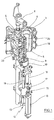
- the device for forming the container (2) consists in Substantially from a blowing station (3), which with a Blow mold (4) into which a preform (1) can be used.
- the preform (1) can be injection-molded part of polyethylene terephthalate be. to Enabling insertion of the preform (1) in the Blow mold (4) and to enable removal of the finished container (2) consists of the blow mold (4) Mold halves (5, 6) and a bottom part (7) of a Lifting device (8) is positionable.
- the preform (1) can in the area of blow station (3) from a transport mandrel (9), which together with the preform (1) a plurality of treatment stations within the Device undergoes. But it is also possible, the Preform (1) for example via pliers or others Use handling agent directly in the blow mold (4).
- a connecting piston (10) arranged which supplies compressed air to the preform (1) and at the same time a seal relative to the transport mandrel (9) makes.
- a connecting piston (10) arranged which supplies compressed air to the preform (1) and at the same time a seal relative to the transport mandrel (9) makes.
- a stretching of the preform (1) takes place with the aid of a Stretching bar (11), positioned by a cylinder (12) becomes.
- a mechanical positioning of the stretch rod (11) over Curve segments to perform by Abgriffrollen are charged.
- the use of curve segments is especially useful when a plurality of Blowing stations (3) arranged on a rotating blowing wheel are.
- a use of cylinders (12) is appropriate if stationarily arranged blowing stations (3) provided are.
- Fig. 1 is the Stretching system designed such that a tandem arrangement of two cylinders (12) is provided. Of a Primary cylinder (13), the stretch rod (11) before Beginning of the actual stretching process up to the area a bottom (14) of the preform (1) driven. While the actual stretching process, the primary cylinder (13) with extended stretch rod together with a Primary cylinder (13) carrying carriage (15) of a Secondary cylinder (16) or via a cam control positioned.
- the Use secondary cylinder (16) in a cam-controlled manner that of a guide roller (17) during the Carrying out the stretching process along a curved path slides, a current stretching position is specified.
- the Guide roller (17) is from the secondary cylinder (16) against the Guideway pressed.
- the carriage (15) slides along of two guide elements (18).
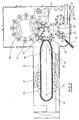
- FIG. 2 To adapt to different shapes of a mouth section (21) of the preform (1) is shown in FIG. 2 the Use of separate thread inserts (22) in the area of Blow mold (4) provided.
- Fig. 2 shows in addition to the blown container (2) also Dashed lines drawn the preform (1) and schematically a developing container bladder (23).
- Fig. 3 shows the basic structure of a Blowing machine, with a heating line (24) and a rotating blowing wheel (25) is provided.
- a heating line (24) Starting from one Preform insert (26) are the preforms (1) of Transfer wheels (27, 28, 29) in the area of the heating section (24) transported.
- Radiant heater (30) and blower (31) arranged to the To temper preforms (1).
- the finished blown containers (2) become from a further transfer wheels a discharge line (32) supplied.
- thermoplastic material can be different Plastics are used. Can be used for example PET, PEN or PP.
- the expansion of the preform (1) during the orientation process done by compressed air supply.
- the Compressed air supply is in a Vorblasphase, in the gas, for example, compressed air, with a low pressure level is fed and in a subsequent Main blowing phase divided, in the gas with a higher Pressure level is supplied.
- the Vorblasphase becomes typically compressed air with a pressure in the interval of 10 bar to 25 bar and during the main blowing phase is compressed air with a pressure in the interval of 25 bar up 40 bar supplied.
- Fig. 3 From Fig. 3 is also seen that in the illustrated embodiment, the heating section (24) a plurality of circulating transport elements (33) is formed, the chain-like strung together and along guide wheels (34) are guided. Especially is thought of by the chain-like arrangement in the réellespannen essential rectangular basic contour. at the illustrated embodiment are in the area of the Transfer wheel (29) and an input wheel (35) facing Extension of the heating section (24) a single relatively large dimensioned deflection wheel (34) and in the range of two adjacent deflections two comparatively smaller dimensioned deflection wheels (36) used. in principle but also any other guides are conceivable.
- the illustrated arrangement proves to be particularly useful, since in the area of the corresponding Extension of the heating section (24) three deflection wheels (34, 36) are positioned, and in each case the smaller ones Deflection wheels (36) in the region of the transition to the linear Course of the heating section (24) and the larger deflection (34) in the immediate transfer area to the transfer wheel (29) and to the input wheel (35).
- chain-like transport elements (33) it is for example also possible to use a rotating heating wheel.
- a larger amount of preforms (1) per unit time be tempered.
- the blower (31) direct cooling air in the range of cooling air ducts (39), the associated radiant heaters (30) each opposite and Dispense the cooling air via outflow openings.
- the cooling air channels (39) can in the range of the Radiant heaters (30) opposite surfaces Provide reflectors for the heating radiation, also It is also possible to use the discharged cooling air Cooling of the radiant heater (30) to realize.
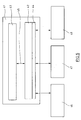
- Fig. 5 shows the basic principle of the control of a Blowing machine.
- a general Machine control To carry out a general Machine control becomes a central machine control (41) used on the basis of a personal computer realized for general applications.
- the Main components of the central machine control (41) are Plug-in boards (42) for specifiable control components, a visualization (43) and a bus interface (44).
- the internal bus (45) may be, for example, a PCI bus be realized.
- the plug-in boards (42) can be used as a slot PLC or soft PLC can be realized.
- the bus interface (44) is in particular to the Intended use of an OPC bus interface.
- a personal computer can be a PC with one graphical user interface similar to a Windows technology be used.
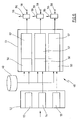
- Fig. 6 shows in more detail part of the Blowing wheel control (48).
- This control component points a position sensor (49) for detecting a Rotational positioning of the blowing wheel (25).
- the Position sensor (49) for example, on the basis a bar code disc be realized.
- measurement information of the position sensor (49) become relative to each other parallel comparators (50) of an evaluation unit (51) fed.
- the comparators (50) receive in addition to the Measurement information of the position sensor (49) Setpoint information of a setpoint input (52).
- the Setpoint specification (52) is with memory locations for individual Setpoint specifications, for example for a pre-blowing pressure (53), a main blowing pressure (54) and a Blow discharge (55) provided. Saved here each position specifications for the corresponding Pressure connection or pressure dissipation, with the Position information of the position sensor (49) compared become.
- valves (56) are typically called realized electromagnetically controlled valves, so that an electrical switching information with low switching time can be converted into a respective valve position.
- the valves (56) typically have pressure inputs (58). and pressure outputs (59), each with the zu switching components are connected.
- the data for the setpoint specification (52) can be read via the Visualization (43) of the central machine control (41) to be provided.
- a storage to enable a continuous target-actual comparison is done but in Area of the evaluation unit (51) and thus independent from the processing cycle of the central machine control (41).
- the comparators (50) and the output stages (57) can be realized for example as analog components be. Basically, however, is also a digital version possible with high clock frequency.
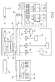
- Fig. 7 shows the structure of the entire control of Blowing machine as a block diagram in a stronger detailed presentation. It is especially noticeable that the central machine control (41) to a Operating data acquisition (60) is connected to the temporal course of a number of operating parameters of Blowing machine detected. In addition, via a modem (61) a connection to a Servicemodem (62) made, the it allows remote diagnosis when occurring Operational disturbances.
- the central machine control (41) is via a electric rotary joint (63), for example as Slip ring assembly may be formed with the Blasrad horrung (48) connected.
- a electric rotary joint for example as Slip ring assembly may be formed with the Blasrad horrung (48) connected.
- contactless couplings for example via an infrared link or via radio transmission, possible.
- the output stages (57) of the evaluation unit (51) are on the valves (56) of the blowing station (3) connected.
- the Blasradmaschineung (48) can also be a control for Servo drives (64) of the stretching rods (11).
- the interface (47) for the machine control is over a bus (65), in particular as a fieldbus may be formed, to the bus interface (44) of the central machine control (41) connected.
- the Interface (47) is equipped with digital inputs (66), digital outputs (67), analog inputs (68) as well as provided with analog outputs (69).
- digital inputs (66) are typically digital reporting members (70) connected to monitoring, the detection of the Machine state and be implemented as a limit switch can.
- the analog inputs (68) are used to connect analog message elements (71), for example as Pyrometer, as pressure transducer, as temperature sensor for used fan, as a temperature sensor for a Cooling water temperature or as a temperature sensor for Heating channels can be formed.
- digital outputs (67) consumers (72) with be connected to digital inputs, for example Valves, displays, relays or contactors.
- digital inputs for example Valves, displays, relays or contactors.
- analog Outputs are used to connect analog actuators (73), for example, for the Vorblastik, the Main blowing pressure, the stretching pressure in pneumatic Stretching systems, the cooling water temperature or the Preform cooling.
- the heating control (46) comprises power parts (74) for Control of the radiant heater (30).
- the radiant heaters can as IR emitters, RF emitters or microwave generators be realized.
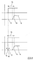
- a starting value (77) in the range of the desired value specification (52) is defined such that taking into account a concrete switching time (78) the pressure value to be reached on Switch-on time (75) is also present.
- the Switching time (78) in the two diagrams shown differ by one valve tolerance (80).
- the respective valve-specific starting values (77) or Correction starting values (79) may be given according to a typical Procedure be determined such that a first Rotation of the blowing wheel with the detection of the valve-specific time delays (78) performed becomes.
- a definition of starting values in the field of Setpoint specification (52) Permanent during operation of the Blowing machine or in cyclic intervals can again one Determination of the individual switching times (78) performed to change, for example, due to a Heating the valves (56) or due to a change to record other operating parameters. It can therefore also a compensation of the switching delays (78) in itself be ensured changing operating parameters.
- Of the entire process can be carried out fully automatically so that for an operator of the machine no additional Operations are required.
- the evaluation unit (51) for specifying the individual Switching times (78) of the valves (56) can be used, for example, as formed a so-called electronic cam switch be. It is also possible to have an interruptible PLC control or another programmable controller use. When using an interruptible PLC controller is used when detecting a degree change in the With regard to the rotational positioning of the blowing wheel the superordinate PLC sequence program interrupted and one Interrupt routine for calculating the switching times (78) the valves (56) activated. In this interrupt routine will be responsible for the speed and accuracy of the Circuit of the valves (56) required functions for Execution of setpoint-actual value comparisons processed.
- interrupt controllers can be very fast cycle times for the comparator functions to be realized in the range of a few microseconds lie.
Applications Claiming Priority (2)
| Application Number | Priority Date | Filing Date | Title |
|---|---|---|---|
| DE10153045A DE10153045A1 (de) | 2001-10-26 | 2001-10-26 | Verfahren und Vorrichtung zur Steuerung eines Blasvorganges |
| DE10153045 | 2001-10-26 |
Publications (3)
| Publication Number | Publication Date |
|---|---|
| EP1306195A2 true EP1306195A2 (fr) | 2003-05-02 |
| EP1306195A3 EP1306195A3 (fr) | 2004-12-15 |
| EP1306195B1 EP1306195B1 (fr) | 2007-06-27 |
Family
ID=7703911
Family Applications (1)
| Application Number | Title | Priority Date | Filing Date |
|---|---|---|---|
| EP02018446A Expired - Lifetime EP1306195B1 (fr) | 2001-10-26 | 2002-08-16 | Procédé et dispositif pour la commande d'une opération de soufflage |
Country Status (3)
| Country | Link |
|---|---|
| EP (1) | EP1306195B1 (fr) |
| AT (1) | ATE365625T1 (fr) |
| DE (2) | DE10153045A1 (fr) |
Cited By (15)
| Publication number | Priority date | Publication date | Assignee | Title |
|---|---|---|---|---|
| WO2005049296A1 (fr) * | 2003-11-17 | 2005-06-02 | Graham Packaging Pet Technologies Inc. | Production continue de recipients en plastique moule |
| EP1566258A2 (fr) * | 2004-02-20 | 2005-08-24 | SIG Technology Ltd. | Appareil pour l'usinage de pièces |
| WO2007028493A2 (fr) * | 2005-09-08 | 2007-03-15 | Krones Ag | Procédé et dispositif pour commander et régler une unite de production de corps creux |
| CN100588534C (zh) * | 2006-09-04 | 2010-02-10 | 广西工学院 | 全自动注吹塑料中空成型机控制装置及其自动控制方法 |
| WO2012016771A1 (fr) * | 2010-08-03 | 2012-02-09 | Krones Ag | Procédé et dispositif d'exploitation d'une installation de manipulation de récipients avec sélection des paramètres de niveau supérieur |
| DE102010049385A1 (de) * | 2010-10-26 | 2012-04-26 | Krones Aktiengesellschaft | Blasmaschine in Modulbauweise |
| EP2213435A3 (fr) * | 2006-05-11 | 2012-08-22 | Krones AG | Dispositif de chauffage pour ébauches en plastique |
| WO2014009654A1 (fr) * | 2012-07-13 | 2014-01-16 | Sidel Participations | Système de commande d'une unité de formage de récipients comprenant une unité de contrôle maître et des contrôleurs esclaves |
| WO2014009653A1 (fr) * | 2012-07-13 | 2014-01-16 | Sidel Participations | Système de commande modulaire d'une installation de fabrication de récipients |
| CN104416889A (zh) * | 2013-09-10 | 2015-03-18 | 广东复兴食品机械有限公司 | 一种用于吹软管软瓶的嵌入式数控立式中空成型装置 |
| US9266276B2 (en) | 2013-10-30 | 2016-02-23 | Krones Ag | Shaping apparatus for the shaping of plastics material pre-forms into plastics material containers |
| CN105960321A (zh) * | 2014-02-12 | 2016-09-21 | 西德尔合作公司 | 利用电动阀打开缺陷的检测用坯件制造容器的方法和装置 |
| FR3053621A1 (fr) * | 2016-07-11 | 2018-01-12 | Sidel Participations | Procede de fabrication de recipients en plastique par soufflage |
| CN107807618A (zh) * | 2017-09-25 | 2018-03-16 | 宁夏共享模具有限公司 | 一种数字化铸造工厂工控系统底层集成架构 |
| WO2020193236A1 (fr) * | 2019-03-22 | 2020-10-01 | Eugen Seitz Ag | Dispositif de soupape de soufflage d'un dispositif soufflant |
Families Citing this family (9)
| Publication number | Priority date | Publication date | Assignee | Title |
|---|---|---|---|---|
| DE10361782B4 (de) * | 2003-12-31 | 2014-08-28 | Khs Corpoplast Gmbh | Vorrichtung zur Bearbeitung von Werkstücken |
| FR2909303B1 (fr) * | 2006-12-05 | 2009-03-27 | Sidel Participations | Procede de fabrication d'un recipient a partir d'une ebauche,avec retroaction en fonction du point de fin d'expansion de l'ebauche |
| FR2909305B1 (fr) * | 2006-12-05 | 2009-03-27 | Sidel Participations | Procede de fabrication d'un recipient a partir d'une ebauche, avec retroaction en fonction du point de developpement de l'ebauche. |
| FR2909304B1 (fr) | 2006-12-05 | 2009-03-27 | Sidel Participations | Procede de fabrication de recipients avec retroaction en fonction du point de debut de presoufflage |
| DE102008012757A1 (de) | 2008-03-05 | 2009-09-10 | Krones Ag | Vorrichtung zum Erzeugen von Kunststoffbehältnissen |
| DE102010047104A1 (de) | 2010-10-01 | 2012-04-05 | Krones Aktiengesellschaft | Vorrichtung zum Umformen von Kunststoffvorformlingen zu Kunststoffbehältnissen mit variabler Ausstoßleistung |
| DE102017114138A1 (de) | 2017-06-26 | 2018-12-27 | Krones Ag | Vorrichtung und Verfahren zur Schaltzeitkompensation am Ventilblock |
| FR3090456B1 (fr) | 2018-12-19 | 2020-11-27 | Sidel Participations | Ligne de production de récipients controlée par un dispositif de détermination de position |
| DE102021115026A1 (de) | 2021-06-10 | 2022-12-15 | Khs Gmbh | Vorrichtung zum Herstellen von Behältern aus thermisch konditionierten Vorformlingen aus thermoplastischem Material |
Citations (6)
| Publication number | Priority date | Publication date | Assignee | Title |
|---|---|---|---|---|
| US5185109A (en) * | 1991-09-12 | 1993-02-09 | Cincinnati Milacron Inc. | Extrusion blow-molding machine control |
| US5244610A (en) * | 1992-02-14 | 1993-09-14 | Plastipak Packaging, Inc. | Rotary plastic blow molding |
| JPH09174673A (ja) * | 1995-12-25 | 1997-07-08 | Mitsubishi Plastics Ind Ltd | 延伸ブロー成形機の監視装置及びその方法 |
| DE19909307A1 (de) * | 1998-03-19 | 1999-09-23 | Siemens Ag | Produktionsmaschine mit elektrischen Antrieben für den Einsatz in der Kunststoffindustrie |
| WO2000016964A1 (fr) * | 1998-09-19 | 2000-03-30 | Krupp Corpoplast Maschinenbau Gmbh | Procede et dispositif pour assurer la commande du moulage de recipients |
| US6186760B1 (en) * | 1997-08-01 | 2001-02-13 | Greig S. Latham | Blow mold machine monitor and control system |
Family Cites Families (1)
| Publication number | Priority date | Publication date | Assignee | Title |
|---|---|---|---|---|
| DE19544634A1 (de) * | 1995-11-30 | 1997-06-05 | Feuerherm Harald | Verfahren zum Blasformen von Hohlkörpern aus thermoplastischem Kunststoff |
-
2001
- 2001-10-26 DE DE10153045A patent/DE10153045A1/de not_active Withdrawn
-
2002
- 2002-08-16 AT AT02018446T patent/ATE365625T1/de active
- 2002-08-16 EP EP02018446A patent/EP1306195B1/fr not_active Expired - Lifetime
- 2002-08-16 DE DE50210373T patent/DE50210373D1/de not_active Expired - Lifetime
Patent Citations (6)
| Publication number | Priority date | Publication date | Assignee | Title |
|---|---|---|---|---|
| US5185109A (en) * | 1991-09-12 | 1993-02-09 | Cincinnati Milacron Inc. | Extrusion blow-molding machine control |
| US5244610A (en) * | 1992-02-14 | 1993-09-14 | Plastipak Packaging, Inc. | Rotary plastic blow molding |
| JPH09174673A (ja) * | 1995-12-25 | 1997-07-08 | Mitsubishi Plastics Ind Ltd | 延伸ブロー成形機の監視装置及びその方法 |
| US6186760B1 (en) * | 1997-08-01 | 2001-02-13 | Greig S. Latham | Blow mold machine monitor and control system |
| DE19909307A1 (de) * | 1998-03-19 | 1999-09-23 | Siemens Ag | Produktionsmaschine mit elektrischen Antrieben für den Einsatz in der Kunststoffindustrie |
| WO2000016964A1 (fr) * | 1998-09-19 | 2000-03-30 | Krupp Corpoplast Maschinenbau Gmbh | Procede et dispositif pour assurer la commande du moulage de recipients |
Non-Patent Citations (1)
| Title |
|---|
| PATENT ABSTRACTS OF JAPAN Bd. 1997, Nr. 11, 28. November 1997 (1997-11-28) & JP 9 174673 A (MITSUBISHI PLASTICS IND LTD), 8. Juli 1997 (1997-07-08) * |
Cited By (37)
| Publication number | Priority date | Publication date | Assignee | Title |
|---|---|---|---|---|
| WO2005049296A1 (fr) * | 2003-11-17 | 2005-06-02 | Graham Packaging Pet Technologies Inc. | Production continue de recipients en plastique moule |
| US7052644B2 (en) | 2003-11-17 | 2006-05-30 | Graham Packaging Pet Technologies, Inc. | Continuous production of molded plastic containers |
| US7220379B2 (en) | 2003-11-17 | 2007-05-22 | Graham Packaging Pet Technologies Inc. | Continuous production of molded plastic containers |
| US7455807B2 (en) | 2003-11-17 | 2008-11-25 | Graham Packaging Pet Technologies Inc. | Continuous production of molded plastic containers |
| EP1566258A2 (fr) * | 2004-02-20 | 2005-08-24 | SIG Technology Ltd. | Appareil pour l'usinage de pièces |
| EP1566258A3 (fr) * | 2004-02-20 | 2005-11-09 | SIG Technology Ltd. | Appareil pour l'usinage de pièces |
| WO2007028493A2 (fr) * | 2005-09-08 | 2007-03-15 | Krones Ag | Procédé et dispositif pour commander et régler une unite de production de corps creux |
| WO2007028493A3 (fr) * | 2005-09-08 | 2007-06-07 | Krones Ag | Procédé et dispositif pour commander et régler une unite de production de corps creux |
| EP2796270A1 (fr) * | 2005-09-08 | 2014-10-29 | Krones AG | Procédé et dispositif pour renvoyer l'air de soufflage d'un récipient moulé par soufflage à un compresseur à plusieurs étages. |
| EP3187326A1 (fr) * | 2005-09-08 | 2017-07-05 | Krones AG | Procédé et dispositif de commande et réglage d'une unité de fabrication de corps creux |
| DE102005042926B4 (de) * | 2005-09-08 | 2015-02-05 | Krones Aktiengesellschaft | Verfahren und Vorrichtung zur Steuerung und Regelung einer Hohlkörperherstellungseinheit |
| EP2213435A3 (fr) * | 2006-05-11 | 2012-08-22 | Krones AG | Dispositif de chauffage pour ébauches en plastique |
| CN100588534C (zh) * | 2006-09-04 | 2010-02-10 | 广西工学院 | 全自动注吹塑料中空成型机控制装置及其自动控制方法 |
| WO2012016771A1 (fr) * | 2010-08-03 | 2012-02-09 | Krones Ag | Procédé et dispositif d'exploitation d'une installation de manipulation de récipients avec sélection des paramètres de niveau supérieur |
| US9375878B2 (en) | 2010-08-03 | 2016-06-28 | Krones Ag | Method and apparatus for operating a plant for the treatment of containers with superordinated choice of parameters |
| CN103052567A (zh) * | 2010-08-03 | 2013-04-17 | 克朗斯股份公司 | 使用升级的参数选择对用于处理容器的设备进行操作的方法和机构 |
| CN103052567B (zh) * | 2010-08-03 | 2014-12-03 | 克朗斯股份公司 | 使用升级的参数选择对用于处理容器的设备进行操作的方法和机构 |
| DE102010049385A1 (de) * | 2010-10-26 | 2012-04-26 | Krones Aktiengesellschaft | Blasmaschine in Modulbauweise |
| US9004905B2 (en) | 2010-10-26 | 2015-04-14 | Krones Ag | Blow moulding machine in a modular design |
| WO2014009654A1 (fr) * | 2012-07-13 | 2014-01-16 | Sidel Participations | Système de commande d'une unité de formage de récipients comprenant une unité de contrôle maître et des contrôleurs esclaves |
| WO2014009653A1 (fr) * | 2012-07-13 | 2014-01-16 | Sidel Participations | Système de commande modulaire d'une installation de fabrication de récipients |
| CN104470700A (zh) * | 2012-07-13 | 2015-03-25 | 西德尔合作公司 | 容器成形单元的包括主控制单元和从控制器的控制系统 |
| FR2993198A1 (fr) * | 2012-07-13 | 2014-01-17 | Sidel Participations | Systeme de commande d'une unite de formage de recipients comprenant une unite de controle maitre et des controleurs esclaves |
| US9676136B2 (en) | 2012-07-13 | 2017-06-13 | Sidel Participations | Control system of a container forming unit comprising a master control unit and slave controllers |
| FR2993199A1 (fr) * | 2012-07-13 | 2014-01-17 | Sidel Participations | Systeme de commande modulaire d'une installation de fabrication de recipients |
| CN104416889A (zh) * | 2013-09-10 | 2015-03-18 | 广东复兴食品机械有限公司 | 一种用于吹软管软瓶的嵌入式数控立式中空成型装置 |
| US9266276B2 (en) | 2013-10-30 | 2016-02-23 | Krones Ag | Shaping apparatus for the shaping of plastics material pre-forms into plastics material containers |
| CN105960321A (zh) * | 2014-02-12 | 2016-09-21 | 西德尔合作公司 | 利用电动阀打开缺陷的检测用坯件制造容器的方法和装置 |
| CN105960321B (zh) * | 2014-02-12 | 2018-12-28 | 西德尔合作公司 | 利用电动阀打开缺陷的检测用坯件制造容器的方法和装置 |
| FR3053621A1 (fr) * | 2016-07-11 | 2018-01-12 | Sidel Participations | Procede de fabrication de recipients en plastique par soufflage |
| WO2018011490A1 (fr) * | 2016-07-11 | 2018-01-18 | Sidel Participations | Procede de fabrication de recipients en plastique par soufflage |
| US11618203B2 (en) | 2016-07-11 | 2023-04-04 | Sidel Participations | Method for manufacturing plastic containers by blow molding |
| EP3481617B1 (fr) | 2016-07-11 | 2020-09-16 | Sidel Participations | Procede de fabrication de recipients en plastique par soufflage |
| CN107807618A (zh) * | 2017-09-25 | 2018-03-16 | 宁夏共享模具有限公司 | 一种数字化铸造工厂工控系统底层集成架构 |
| CN107807618B (zh) * | 2017-09-25 | 2020-09-15 | 共享智能装备有限公司 | 一种数字化铸造工厂工控系统底层集成架构 |
| CN113613863A (zh) * | 2019-03-22 | 2021-11-05 | 欧根赛驰股份公司 | 吹塑设备的吹塑阀设备 |
| WO2020193236A1 (fr) * | 2019-03-22 | 2020-10-01 | Eugen Seitz Ag | Dispositif de soupape de soufflage d'un dispositif soufflant |
Also Published As
| Publication number | Publication date |
|---|---|
| EP1306195B1 (fr) | 2007-06-27 |
| ATE365625T1 (de) | 2007-07-15 |
| EP1306195A3 (fr) | 2004-12-15 |
| DE10153045A1 (de) | 2003-05-08 |
| DE50210373D1 (de) | 2007-08-09 |
Similar Documents
| Publication | Publication Date | Title |
|---|---|---|
| EP1306195A2 (fr) | Procédé et dispositif pour la commande d'une opération de soufflage | |
| EP2352633B1 (fr) | Procédé et dispositif de moulage de contenants par soufflage | |
| EP2247429B1 (fr) | Procédé et dispositif de moulage par soufflage de récipients | |
| EP2470348B1 (fr) | Procédé et dispositif de moulage par soufflage de contenants | |
| EP2098356B1 (fr) | Dispositif et procédé de production de récipients de matière plastique | |
| EP1998950B1 (fr) | PROCEDE ET DISPOSITIF DE FORMAge-SOUFFLAGE DE RECIPIENTS PAR RECOURS A LA MESURE DE L'EPAISSEUR DE PAROIS DE L'OBJET FACONNE | |
| EP1910056B1 (fr) | Procede et dispositif de positionnement d'un composant | |
| WO2000016964A1 (fr) | Procede et dispositif pour assurer la commande du moulage de recipients | |
| EP2188108B2 (fr) | Procédé de moulage par soufflage de récipients | |
| EP2618986B1 (fr) | Procédé et dispositif de moulage par soufflage de récipients | |
| DE10116665B4 (de) | Verfahren zur Steuerung eines Blasvorgangs bei der Herstellung von Behältern aus einem thermoplastischen Material | |
| EP2081752B1 (fr) | Procédé et dispositif de formage-soufflage de récipients | |
| EP2307185A1 (fr) | Procédé et dispositif de moulage par soufflage de contenants | |
| EP1484160A1 (fr) | Appareil pour le moulage par souffllage de récipients avec une tige dont l'étirage est obtenu au moyen d'un moteur linéaire | |
| EP1574318B1 (fr) | Procédé et appareil de formage de récipients par soufflage | |
| EP1566258B1 (fr) | Appareil pour l'usinage de pièces | |
| EP1226017B1 (fr) | Procede et dispositif de formage par soufflage de contenants | |
| DE10357247A1 (de) | Verfahren und Vorrichtung zur Bearbeitung von Werkstücken | |
| EP2044334B1 (fr) | Procede et dispositif de formage de recipients par soufflage | |
| DE102018117849A1 (de) | Verfahren und Vorrichtung zum Umformen von Kunststoffvorformlingen zu Kunststoffbehältnissen mit Vortemperierung von Blasformen | |
| EP1473139A1 (fr) | Procédé et appareil de formage de récipients par soufflage | |
| WO2002020245A1 (fr) | Dispositif pour produire des paraisons | |
| WO2001039958A1 (fr) | Procede et dispositif de moulage par soufflage de recipients |
Legal Events
| Date | Code | Title | Description |
|---|---|---|---|
| PUAI | Public reference made under article 153(3) epc to a published international application that has entered the european phase |
Free format text: ORIGINAL CODE: 0009012 |
|
| AK | Designated contracting states |
Designated state(s): AT BE BG CH CY CZ DE DK EE ES FI FR GB GR IE IT LI LU MC NL PT SE SK TR |
|
| AX | Request for extension of the european patent |
Extension state: AL LT LV MK RO SI |
|
| PUAL | Search report despatched |
Free format text: ORIGINAL CODE: 0009013 |
|
| AK | Designated contracting states |
Kind code of ref document: A3 Designated state(s): AT BE BG CH CY CZ DE DK EE ES FI FR GB GR IE IT LI LU MC NL PT SE SK TR |
|
| AX | Request for extension of the european patent |
Extension state: AL LT LV MK RO SI |
|
| RIC1 | Information provided on ipc code assigned before grant |
Ipc: 7G 05B 19/04 B Ipc: 7B 29C 49/78 A Ipc: 7B 29L 22:00 Z Ipc: 7B 29K 67:00 Z |
|
| 17P | Request for examination filed |
Effective date: 20041228 |
|
| 17Q | First examination report despatched |
Effective date: 20050131 |
|
| AKX | Designation fees paid |
Designated state(s): AT BE BG CH CY CZ DE DK EE ES FI FR GB GR IE IT LI LU MC NL PT SE SK TR |
|
| GRAP | Despatch of communication of intention to grant a patent |
Free format text: ORIGINAL CODE: EPIDOSNIGR1 |
|
| RIC1 | Information provided on ipc code assigned before grant |
Ipc: B29K 67/00 20060101ALN20070214BHEP Ipc: B29C 49/78 20060101AFI20070214BHEP Ipc: B29L 22/00 20060101ALN20070214BHEP Ipc: G05B 19/04 20060101ALI20070214BHEP |
|
| GRAS | Grant fee paid |
Free format text: ORIGINAL CODE: EPIDOSNIGR3 |
|
| GRAA | (expected) grant |
Free format text: ORIGINAL CODE: 0009210 |
|
| AK | Designated contracting states |
Kind code of ref document: B1 Designated state(s): AT BE BG CH CY CZ DE DK EE ES FI FR GB GR IE IT LI LU MC NL PT SE SK TR |
|
| REG | Reference to a national code |
Ref country code: GB Ref legal event code: FG4D Free format text: NOT ENGLISH |
|
| REG | Reference to a national code |
Ref country code: CH Ref legal event code: EP |
|
| REG | Reference to a national code |
Ref country code: IE Ref legal event code: FG4D Free format text: LANGUAGE OF EP DOCUMENT: GERMAN |
|
| REF | Corresponds to: |
Ref document number: 50210373 Country of ref document: DE Date of ref document: 20070809 Kind code of ref document: P |
|
| PG25 | Lapsed in a contracting state [announced via postgrant information from national office to epo] |
Ref country code: SE Free format text: LAPSE BECAUSE OF FAILURE TO SUBMIT A TRANSLATION OF THE DESCRIPTION OR TO PAY THE FEE WITHIN THE PRESCRIBED TIME-LIMIT Effective date: 20070927 |
|
| ET | Fr: translation filed | ||
| NLV1 | Nl: lapsed or annulled due to failure to fulfill the requirements of art. 29p and 29m of the patents act | ||
| GBV | Gb: ep patent (uk) treated as always having been void in accordance with gb section 77(7)/1977 [no translation filed] |
Effective date: 20070627 |
|
| REG | Reference to a national code |
Ref country code: IE Ref legal event code: FD4D |
|
| REG | Reference to a national code |
Ref country code: GB Ref legal event code: 732E |
|
| PG25 | Lapsed in a contracting state [announced via postgrant information from national office to epo] |
Ref country code: BG Free format text: LAPSE BECAUSE OF FAILURE TO SUBMIT A TRANSLATION OF THE DESCRIPTION OR TO PAY THE FEE WITHIN THE PRESCRIBED TIME-LIMIT Effective date: 20070927 Ref country code: ES Free format text: LAPSE BECAUSE OF FAILURE TO SUBMIT A TRANSLATION OF THE DESCRIPTION OR TO PAY THE FEE WITHIN THE PRESCRIBED TIME-LIMIT Effective date: 20071008 Ref country code: CZ Free format text: LAPSE BECAUSE OF FAILURE TO SUBMIT A TRANSLATION OF THE DESCRIPTION OR TO PAY THE FEE WITHIN THE PRESCRIBED TIME-LIMIT Effective date: 20070627 Ref country code: PT Free format text: LAPSE BECAUSE OF FAILURE TO SUBMIT A TRANSLATION OF THE DESCRIPTION OR TO PAY THE FEE WITHIN THE PRESCRIBED TIME-LIMIT Effective date: 20071127 Ref country code: IE Free format text: LAPSE BECAUSE OF FAILURE TO SUBMIT A TRANSLATION OF THE DESCRIPTION OR TO PAY THE FEE WITHIN THE PRESCRIBED TIME-LIMIT Effective date: 20070627 Ref country code: NL Free format text: LAPSE BECAUSE OF FAILURE TO SUBMIT A TRANSLATION OF THE DESCRIPTION OR TO PAY THE FEE WITHIN THE PRESCRIBED TIME-LIMIT Effective date: 20070627 |
|
| BERE | Be: lapsed |
Owner name: SIG CORPOPLAST G.M.B.H. & CO. KG Effective date: 20070831 |
|
| PG25 | Lapsed in a contracting state [announced via postgrant information from national office to epo] |
Ref country code: SK Free format text: LAPSE BECAUSE OF FAILURE TO SUBMIT A TRANSLATION OF THE DESCRIPTION OR TO PAY THE FEE WITHIN THE PRESCRIBED TIME-LIMIT Effective date: 20070627 |
|
| REG | Reference to a national code |
Ref country code: CH Ref legal event code: PL |
|
| PG25 | Lapsed in a contracting state [announced via postgrant information from national office to epo] |
Ref country code: DK Free format text: LAPSE BECAUSE OF FAILURE TO SUBMIT A TRANSLATION OF THE DESCRIPTION OR TO PAY THE FEE WITHIN THE PRESCRIBED TIME-LIMIT Effective date: 20070627 Ref country code: CH Free format text: LAPSE BECAUSE OF NON-PAYMENT OF DUE FEES Effective date: 20070831 Ref country code: GR Free format text: LAPSE BECAUSE OF FAILURE TO SUBMIT A TRANSLATION OF THE DESCRIPTION OR TO PAY THE FEE WITHIN THE PRESCRIBED TIME-LIMIT Effective date: 20070928 Ref country code: LI Free format text: LAPSE BECAUSE OF NON-PAYMENT OF DUE FEES Effective date: 20070831 Ref country code: MC Free format text: LAPSE BECAUSE OF NON-PAYMENT OF DUE FEES Effective date: 20070831 |
|
| PLBE | No opposition filed within time limit |
Free format text: ORIGINAL CODE: 0009261 |
|
| STAA | Information on the status of an ep patent application or granted ep patent |
Free format text: STATUS: NO OPPOSITION FILED WITHIN TIME LIMIT |
|
| PG25 | Lapsed in a contracting state [announced via postgrant information from national office to epo] |
Ref country code: GB Free format text: LAPSE BECAUSE OF FAILURE TO SUBMIT A TRANSLATION OF THE DESCRIPTION OR TO PAY THE FEE WITHIN THE PRESCRIBED TIME-LIMIT Effective date: 20070627 |
|
| 26N | No opposition filed |
Effective date: 20080328 |
|
| PG25 | Lapsed in a contracting state [announced via postgrant information from national office to epo] |
Ref country code: BE Free format text: LAPSE BECAUSE OF NON-PAYMENT OF DUE FEES Effective date: 20070831 |
|
| PG25 | Lapsed in a contracting state [announced via postgrant information from national office to epo] |
Ref country code: EE Free format text: LAPSE BECAUSE OF FAILURE TO SUBMIT A TRANSLATION OF THE DESCRIPTION OR TO PAY THE FEE WITHIN THE PRESCRIBED TIME-LIMIT Effective date: 20070627 |
|
| PG25 | Lapsed in a contracting state [announced via postgrant information from national office to epo] |
Ref country code: FI Free format text: LAPSE BECAUSE OF FAILURE TO SUBMIT A TRANSLATION OF THE DESCRIPTION OR TO PAY THE FEE WITHIN THE PRESCRIBED TIME-LIMIT Effective date: 20070627 |
|
| PG25 | Lapsed in a contracting state [announced via postgrant information from national office to epo] |
Ref country code: CY Free format text: LAPSE BECAUSE OF FAILURE TO SUBMIT A TRANSLATION OF THE DESCRIPTION OR TO PAY THE FEE WITHIN THE PRESCRIBED TIME-LIMIT Effective date: 20070627 |
|
| PG25 | Lapsed in a contracting state [announced via postgrant information from national office to epo] |
Ref country code: LU Free format text: LAPSE BECAUSE OF NON-PAYMENT OF DUE FEES Effective date: 20070816 |
|
| PG25 | Lapsed in a contracting state [announced via postgrant information from national office to epo] |
Ref country code: TR Free format text: LAPSE BECAUSE OF FAILURE TO SUBMIT A TRANSLATION OF THE DESCRIPTION OR TO PAY THE FEE WITHIN THE PRESCRIBED TIME-LIMIT Effective date: 20070627 |
|
| REG | Reference to a national code |
Ref country code: FR Ref legal event code: CD |
|
| REG | Reference to a national code |
Ref country code: DE Ref legal event code: R081 Ref document number: 50210373 Country of ref document: DE Owner name: KHS CORPOPLAST GMBH, DE Free format text: FORMER OWNER: KHS CORPOPLAST GMBH & CO. KG, 22145 HAMBURG, DE Effective date: 20110504 |
|
| REG | Reference to a national code |
Ref country code: DE Ref legal event code: R082 Ref document number: 50210373 Country of ref document: DE |
|
| REG | Reference to a national code |
Ref country code: FR Ref legal event code: PLFP Year of fee payment: 15 |
|
| REG | Reference to a national code |
Ref country code: FR Ref legal event code: PLFP Year of fee payment: 16 |
|
| REG | Reference to a national code |
Ref country code: FR Ref legal event code: PLFP Year of fee payment: 17 |
|
| PGFP | Annual fee paid to national office [announced via postgrant information from national office to epo] |
Ref country code: IT Payment date: 20210830 Year of fee payment: 20 Ref country code: AT Payment date: 20210820 Year of fee payment: 20 Ref country code: FR Payment date: 20210819 Year of fee payment: 20 |
|
| PGFP | Annual fee paid to national office [announced via postgrant information from national office to epo] |
Ref country code: DE Payment date: 20210819 Year of fee payment: 20 |
|
| REG | Reference to a national code |
Ref country code: DE Ref legal event code: R081 Ref document number: 50210373 Country of ref document: DE Owner name: KHS GMBH, DE Free format text: FORMER OWNER: KHS CORPOPLAST GMBH, 22145 HAMBURG, DE |
|
| REG | Reference to a national code |
Ref country code: DE Ref legal event code: R071 Ref document number: 50210373 Country of ref document: DE |
|
| REG | Reference to a national code |
Ref country code: AT Ref legal event code: MK07 Ref document number: 365625 Country of ref document: AT Kind code of ref document: T Effective date: 20220816 |
|
| REG | Reference to a national code |
Ref country code: AT Ref legal event code: PC Ref document number: 365625 Country of ref document: AT Kind code of ref document: T Owner name: KHS GMBH, DE Effective date: 20220921 |