EP1306195A2 - Process and apparatus for controlling a blow operation - Google Patents
Process and apparatus for controlling a blow operation Download PDFInfo
- Publication number
- EP1306195A2 EP1306195A2 EP02018446A EP02018446A EP1306195A2 EP 1306195 A2 EP1306195 A2 EP 1306195A2 EP 02018446 A EP02018446 A EP 02018446A EP 02018446 A EP02018446 A EP 02018446A EP 1306195 A2 EP1306195 A2 EP 1306195A2
- Authority
- EP
- European Patent Office
- Prior art keywords
- blowing
- central machine
- evaluation unit
- control
- valves
- Prior art date
- Legal status (The legal status is an assumption and is not a legal conclusion. Google has not performed a legal analysis and makes no representation as to the accuracy of the status listed.)
- Granted
Links
- 238000000034 method Methods 0.000 title claims description 32
- 230000008569 process Effects 0.000 title claims description 16
- 238000005259 measurement Methods 0.000 claims abstract description 11
- 238000012545 processing Methods 0.000 claims abstract description 11
- 238000007664 blowing Methods 0.000 claims description 72
- 238000011156 evaluation Methods 0.000 claims description 37
- 238000010438 heat treatment Methods 0.000 claims description 20
- 230000005540 biological transmission Effects 0.000 claims description 10
- 238000000071 blow moulding Methods 0.000 claims description 10
- 238000004519 manufacturing process Methods 0.000 claims description 10
- 238000012800 visualization Methods 0.000 claims description 8
- 230000001934 delay Effects 0.000 claims description 7
- 230000004044 response Effects 0.000 claims description 6
- 230000008878 coupling Effects 0.000 claims description 5
- 238000010168 coupling process Methods 0.000 claims description 5
- 238000005859 coupling reaction Methods 0.000 claims description 5
- 238000001514 detection method Methods 0.000 claims description 5
- 239000012530 fluid Substances 0.000 claims description 5
- 230000006870 function Effects 0.000 claims description 5
- 230000006978 adaptation Effects 0.000 claims description 4
- 230000001419 dependent effect Effects 0.000 claims description 2
- 229920001169 thermoplastic Polymers 0.000 claims description 2
- 239000004416 thermosoftening plastic Substances 0.000 claims description 2
- 238000001816 cooling Methods 0.000 description 8
- 238000010586 diagram Methods 0.000 description 8
- 238000012546 transfer Methods 0.000 description 7
- 239000000463 material Substances 0.000 description 4
- 229920000139 polyethylene terephthalate Polymers 0.000 description 4
- 239000005020 polyethylene terephthalate Substances 0.000 description 4
- 230000008859 change Effects 0.000 description 3
- 238000009826 distribution Methods 0.000 description 3
- 238000000465 moulding Methods 0.000 description 3
- 238000010276 construction Methods 0.000 description 2
- 239000000498 cooling water Substances 0.000 description 2
- 238000012937 correction Methods 0.000 description 2
- 238000013461 design Methods 0.000 description 2
- 238000001746 injection moulding Methods 0.000 description 2
- -1 polyethylene terephthalate Polymers 0.000 description 2
- 239000012815 thermoplastic material Substances 0.000 description 2
- 230000004913 activation Effects 0.000 description 1
- 230000000712 assembly Effects 0.000 description 1
- 238000000429 assembly Methods 0.000 description 1
- 230000006399 behavior Effects 0.000 description 1
- 230000009286 beneficial effect Effects 0.000 description 1
- 230000015572 biosynthetic process Effects 0.000 description 1
- 239000000969 carrier Substances 0.000 description 1
- 239000003795 chemical substances by application Substances 0.000 description 1
- 230000001143 conditioned effect Effects 0.000 description 1
- 125000004122 cyclic group Chemical group 0.000 description 1
- 238000009795 derivation Methods 0.000 description 1
- 230000000694 effects Effects 0.000 description 1
- 238000005516 engineering process Methods 0.000 description 1
- 235000013305 food Nutrition 0.000 description 1
- 238000003780 insertion Methods 0.000 description 1
- 230000037431 insertion Effects 0.000 description 1
- 230000003993 interaction Effects 0.000 description 1
- 238000012544 monitoring process Methods 0.000 description 1
- 230000005693 optoelectronics Effects 0.000 description 1
- 239000004033 plastic Substances 0.000 description 1
- 229920003023 plastic Polymers 0.000 description 1
- 230000005855 radiation Effects 0.000 description 1
- 238000004171 remote diagnosis Methods 0.000 description 1
- 239000007787 solid Substances 0.000 description 1
- 238000007711 solidification Methods 0.000 description 1
- 230000008023 solidification Effects 0.000 description 1
- 238000003860 storage Methods 0.000 description 1
- 238000005496 tempering Methods 0.000 description 1
- 230000002123 temporal effect Effects 0.000 description 1
- 230000007704 transition Effects 0.000 description 1
Images


Classifications
-
- B—PERFORMING OPERATIONS; TRANSPORTING
- B29—WORKING OF PLASTICS; WORKING OF SUBSTANCES IN A PLASTIC STATE IN GENERAL
- B29C—SHAPING OR JOINING OF PLASTICS; SHAPING OF MATERIAL IN A PLASTIC STATE, NOT OTHERWISE PROVIDED FOR; AFTER-TREATMENT OF THE SHAPED PRODUCTS, e.g. REPAIRING
- B29C49/00—Blow-moulding, i.e. blowing a preform or parison to a desired shape within a mould; Apparatus therefor
- B29C49/42—Component parts, details or accessories; Auxiliary operations
- B29C49/78—Measuring, controlling or regulating
-
- B—PERFORMING OPERATIONS; TRANSPORTING
- B29—WORKING OF PLASTICS; WORKING OF SUBSTANCES IN A PLASTIC STATE IN GENERAL
- B29C—SHAPING OR JOINING OF PLASTICS; SHAPING OF MATERIAL IN A PLASTIC STATE, NOT OTHERWISE PROVIDED FOR; AFTER-TREATMENT OF THE SHAPED PRODUCTS, e.g. REPAIRING
- B29C35/00—Heating, cooling or curing, e.g. crosslinking or vulcanising; Apparatus therefor
- B29C35/02—Heating or curing, e.g. crosslinking or vulcanizing during moulding, e.g. in a mould
- B29C35/08—Heating or curing, e.g. crosslinking or vulcanizing during moulding, e.g. in a mould by wave energy or particle radiation
- B29C35/0805—Heating or curing, e.g. crosslinking or vulcanizing during moulding, e.g. in a mould by wave energy or particle radiation using electromagnetic radiation
- B29C2035/0822—Heating or curing, e.g. crosslinking or vulcanizing during moulding, e.g. in a mould by wave energy or particle radiation using electromagnetic radiation using IR radiation
-
- B—PERFORMING OPERATIONS; TRANSPORTING
- B29—WORKING OF PLASTICS; WORKING OF SUBSTANCES IN A PLASTIC STATE IN GENERAL
- B29C—SHAPING OR JOINING OF PLASTICS; SHAPING OF MATERIAL IN A PLASTIC STATE, NOT OTHERWISE PROVIDED FOR; AFTER-TREATMENT OF THE SHAPED PRODUCTS, e.g. REPAIRING
- B29C35/00—Heating, cooling or curing, e.g. crosslinking or vulcanising; Apparatus therefor
- B29C35/02—Heating or curing, e.g. crosslinking or vulcanizing during moulding, e.g. in a mould
- B29C35/08—Heating or curing, e.g. crosslinking or vulcanizing during moulding, e.g. in a mould by wave energy or particle radiation
- B29C35/0805—Heating or curing, e.g. crosslinking or vulcanizing during moulding, e.g. in a mould by wave energy or particle radiation using electromagnetic radiation
- B29C2035/0855—Heating or curing, e.g. crosslinking or vulcanizing during moulding, e.g. in a mould by wave energy or particle radiation using electromagnetic radiation using microwave
-
- B—PERFORMING OPERATIONS; TRANSPORTING
- B29—WORKING OF PLASTICS; WORKING OF SUBSTANCES IN A PLASTIC STATE IN GENERAL
- B29C—SHAPING OR JOINING OF PLASTICS; SHAPING OF MATERIAL IN A PLASTIC STATE, NOT OTHERWISE PROVIDED FOR; AFTER-TREATMENT OF THE SHAPED PRODUCTS, e.g. REPAIRING
- B29C49/00—Blow-moulding, i.e. blowing a preform or parison to a desired shape within a mould; Apparatus therefor
- B29C49/42—Component parts, details or accessories; Auxiliary operations
- B29C49/78—Measuring, controlling or regulating
- B29C49/783—Measuring, controlling or regulating blowing pressure
- B29C2049/7832—Blowing with two or more pressure levels
-
- B—PERFORMING OPERATIONS; TRANSPORTING
- B29—WORKING OF PLASTICS; WORKING OF SUBSTANCES IN A PLASTIC STATE IN GENERAL
- B29C—SHAPING OR JOINING OF PLASTICS; SHAPING OF MATERIAL IN A PLASTIC STATE, NOT OTHERWISE PROVIDED FOR; AFTER-TREATMENT OF THE SHAPED PRODUCTS, e.g. REPAIRING
- B29C49/00—Blow-moulding, i.e. blowing a preform or parison to a desired shape within a mould; Apparatus therefor
- B29C49/42—Component parts, details or accessories; Auxiliary operations
- B29C49/78—Measuring, controlling or regulating
- B29C2049/788—Controller type or interface
- B29C2049/78805—Computer or PLC control
-
- B—PERFORMING OPERATIONS; TRANSPORTING
- B29—WORKING OF PLASTICS; WORKING OF SUBSTANCES IN A PLASTIC STATE IN GENERAL
- B29C—SHAPING OR JOINING OF PLASTICS; SHAPING OF MATERIAL IN A PLASTIC STATE, NOT OTHERWISE PROVIDED FOR; AFTER-TREATMENT OF THE SHAPED PRODUCTS, e.g. REPAIRING
- B29C2949/00—Indexing scheme relating to blow-moulding
- B29C2949/07—Preforms or parisons characterised by their configuration
- B29C2949/0715—Preforms or parisons characterised by their configuration the preform having one end closed
-
- B—PERFORMING OPERATIONS; TRANSPORTING
- B29—WORKING OF PLASTICS; WORKING OF SUBSTANCES IN A PLASTIC STATE IN GENERAL
- B29C—SHAPING OR JOINING OF PLASTICS; SHAPING OF MATERIAL IN A PLASTIC STATE, NOT OTHERWISE PROVIDED FOR; AFTER-TREATMENT OF THE SHAPED PRODUCTS, e.g. REPAIRING
- B29C49/00—Blow-moulding, i.e. blowing a preform or parison to a desired shape within a mould; Apparatus therefor
- B29C49/02—Combined blow-moulding and manufacture of the preform or the parison
- B29C49/06—Injection blow-moulding
-
- B—PERFORMING OPERATIONS; TRANSPORTING
- B29—WORKING OF PLASTICS; WORKING OF SUBSTANCES IN A PLASTIC STATE IN GENERAL
- B29C—SHAPING OR JOINING OF PLASTICS; SHAPING OF MATERIAL IN A PLASTIC STATE, NOT OTHERWISE PROVIDED FOR; AFTER-TREATMENT OF THE SHAPED PRODUCTS, e.g. REPAIRING
- B29C49/00—Blow-moulding, i.e. blowing a preform or parison to a desired shape within a mould; Apparatus therefor
- B29C49/08—Biaxial stretching during blow-moulding
- B29C49/10—Biaxial stretching during blow-moulding using mechanical means for prestretching
- B29C49/12—Stretching rods
-
- B—PERFORMING OPERATIONS; TRANSPORTING
- B29—WORKING OF PLASTICS; WORKING OF SUBSTANCES IN A PLASTIC STATE IN GENERAL
- B29C—SHAPING OR JOINING OF PLASTICS; SHAPING OF MATERIAL IN A PLASTIC STATE, NOT OTHERWISE PROVIDED FOR; AFTER-TREATMENT OF THE SHAPED PRODUCTS, e.g. REPAIRING
- B29C49/00—Blow-moulding, i.e. blowing a preform or parison to a desired shape within a mould; Apparatus therefor
- B29C49/08—Biaxial stretching during blow-moulding
- B29C49/10—Biaxial stretching during blow-moulding using mechanical means for prestretching
- B29C49/122—Drive means therefor
- B29C49/1229—Drive means therefor being a cam mechanism
-
- B—PERFORMING OPERATIONS; TRANSPORTING
- B29—WORKING OF PLASTICS; WORKING OF SUBSTANCES IN A PLASTIC STATE IN GENERAL
- B29C—SHAPING OR JOINING OF PLASTICS; SHAPING OF MATERIAL IN A PLASTIC STATE, NOT OTHERWISE PROVIDED FOR; AFTER-TREATMENT OF THE SHAPED PRODUCTS, e.g. REPAIRING
- B29C49/00—Blow-moulding, i.e. blowing a preform or parison to a desired shape within a mould; Apparatus therefor
- B29C49/28—Blow-moulding apparatus
- B29C49/30—Blow-moulding apparatus having movable moulds or mould parts
- B29C49/36—Blow-moulding apparatus having movable moulds or mould parts rotatable about one axis
-
- B—PERFORMING OPERATIONS; TRANSPORTING
- B29—WORKING OF PLASTICS; WORKING OF SUBSTANCES IN A PLASTIC STATE IN GENERAL
- B29C—SHAPING OR JOINING OF PLASTICS; SHAPING OF MATERIAL IN A PLASTIC STATE, NOT OTHERWISE PROVIDED FOR; AFTER-TREATMENT OF THE SHAPED PRODUCTS, e.g. REPAIRING
- B29C49/00—Blow-moulding, i.e. blowing a preform or parison to a desired shape within a mould; Apparatus therefor
- B29C49/42—Component parts, details or accessories; Auxiliary operations
- B29C49/4289—Valve constructions or configurations, e.g. arranged to reduce blowing fluid consumption
-
- B—PERFORMING OPERATIONS; TRANSPORTING
- B29—WORKING OF PLASTICS; WORKING OF SUBSTANCES IN A PLASTIC STATE IN GENERAL
- B29C—SHAPING OR JOINING OF PLASTICS; SHAPING OF MATERIAL IN A PLASTIC STATE, NOT OTHERWISE PROVIDED FOR; AFTER-TREATMENT OF THE SHAPED PRODUCTS, e.g. REPAIRING
- B29C49/00—Blow-moulding, i.e. blowing a preform or parison to a desired shape within a mould; Apparatus therefor
- B29C49/42—Component parts, details or accessories; Auxiliary operations
- B29C49/64—Heating or cooling preforms, parisons or blown articles
- B29C49/68—Ovens specially adapted for heating preforms or parisons
- B29C49/6835—Ovens specially adapted for heating preforms or parisons using reflectors
-
- B—PERFORMING OPERATIONS; TRANSPORTING
- B29—WORKING OF PLASTICS; WORKING OF SUBSTANCES IN A PLASTIC STATE IN GENERAL
- B29K—INDEXING SCHEME ASSOCIATED WITH SUBCLASSES B29B, B29C OR B29D, RELATING TO MOULDING MATERIALS OR TO MATERIALS FOR MOULDS, REINFORCEMENTS, FILLERS OR PREFORMED PARTS, e.g. INSERTS
- B29K2067/00—Use of polyesters or derivatives thereof, as moulding material
Definitions
- the invention relates to a method for controlling a Blowing process, in which on a rotating blowing wheel arranged blowing stations for blow molding of thermoplastic preforms in containers at least one pressurized blowing fluid is supplied and in which at least temporarily a current rotational positioning the blowing wheel detected by measurement and the corresponding Information from an evaluation unit with Switching position presets for the supply and discharge of the Blasfluids are compared.
- the invention further relates to a device for Control of a blowing process, the at least one controllable valve, which is in the range of Supply line is arranged for a blowing fluid and in the the supply line a Blasfluid pumps with at least a blowing station that connects on a rotating Blasrad is arranged and with a measured value and with at least one position sensor for detection a rotational positioning of the blowing wheel is provided as well as with the measured value acquisition with a Evaluation unit is connected to the circuit of the valves.
- the at least one controllable valve which is in the range of Supply line is arranged for a blowing fluid and in the the supply line a Blasfluidmakers with at least a blowing station that connects on a rotating Blasrad is arranged and with a measured value and with at least one position sensor for detection a rotational positioning of the blowing wheel is provided as well as with the measured value acquisition with a Evaluation unit is connected to the circuit of the valves.
- Such methods and devices are particularly used in the production of blow-molded containers, coordinated with the execution of the blowing process Supply of one or more blowing pressures and a Derivation of the blowing pressure after a formation of the To perform container.
- the Preforms as well as the blown containers with the help transported different handling equipment become. Has proven particularly the use of Transport mandrels on which the preforms are attached become.
- the preforms can also be used with others Carrying facilities are handled.
- the usage of Tongs for handling preforms and the Use of expanding mandrels for mounting in a Mouth region of the preform are insertable belong also to the available constructions.
- blowing stations With regard to the blowing stations used different embodiments known. at Blowing stations on rotating transport wheels arranged, is a book - like Aufklappbarkeit the Mold carrier frequently encountered. But it is also possible relative to each other displaceable or otherwise guided Insert mold carrier. In blow molding stations, in particular are suitable for several cavities for container molding Also, next to hinged forms are included parallel plates arranged as a mold carrier used.
- Object of the present invention is therefore, a Specify method of the type mentioned in the introduction that achieved an improved control of the valves can be.
- Evaluation unit independent of a processing cycle a central machine control is operated that at least two comparators of the evaluation unit, the Setpoints for the valve control with actual values from the Link measurement information, the measurement information relative be fed to each other in parallel and simultaneously and that the comparators via output stages directly to the Acting valves.
- Another object of the present invention is to provide a Device of the type mentioned in the introduction to such Construct that the production of containers with relative supports mutually identical material distributions becomes.
- the Evaluation unit one of a working cycle one central machine control independent operation has, that the evaluation unit with at least two Comparishers for linking actual signals of the Position sensors and setpoint specifications is provided that the Comparator relative to each other in parallel to the Position sensor are connected and that the Evaluation unit via output stages directly with the Valves is connected.
- each one several valves are assigned. Through a parallel Connection of all comparators to the position sensor is regardless of the switching activities of adjacent valves or neighboring blowing stations an immediate Activation of each affected valve allows.
- the direct coupling of the evaluation unit over the Output stages with the valves also contributes to one short resulting switching time at.
- a simple operating structure is thereby provided that the evaluation unit via a Data interface with the central machine control is coupled.
- Container To support an individual setting in Depending on the design to be produced in each case Container is suggested that from the central Machine control setpoints for the evaluation unit be transmitted.
- a production of containers with relative to each other even material distributions become particular achieved in that different valves different setpoints for a particular control be assigned.
- An advantageous control sequence is that before a production start the blowing wheel at least one Circulation to determine the setpoint switching values for the valves performs.
- a Control panel using a personal computer with inserts for the realization of a programmable controller is performed. This For example, by the use of a so-called Slot PLC or Soft PLC done. For a soft PLC the control by software on the personal computer expires.
- a convenient operating structure is thereby provided that the central machine control Outputs for the transmission of setpoints for the Pressure supply to the blowing stations via the valves having.
- a modular system structure is also supported by that switching position specifications for the evaluation unit of at least one module of the programmable logic controller Control of the central machine control are given.
- the Switching position specifications from a processing unit in the Area of the blowing wheel can be specified.
- the evaluation unit with a Output for the transmission of error messages to the central machine control is provided.
- a substantial function decoupling between the Evaluation unit and the central machine control is realized in that the evaluation unit a Memory for the shift position specifications has.
- a fast data exchange is supported by the fact that the central machine control via a bus with the Evaluation unit is connected.
- a very flexible control structure is also characterized supports that the programmable logic controller of the central machine control via an OPC interface the bus system is connected.
- the bus system via at least one electric rotary coupling with the Evaluation unit is connected.
- This can be, for example in the form of a rotary distributor with slip ring.
- opto-electronics or a radio link possible.
- the central Machine control has an internal flow control, those with different response frequencies for different control functions is provided and at a heating control relative to a Blower wheel control with a lower response frequency and a valve control relative to a Blasrad horrung is provided with a higher response frequency.
- Such Operation can be via a so-called multitasking process be achieved.
- a simple connectivity for different Functional assemblies are provided by the fact that the central machine control at least one open bus system having.
- a transmission of large amounts of data is thereby facilitates the visualization of the central Machine control via a PCI bus with the Programmable logic controller is connected.
- a connection between the Visualization and the already mentioned slot PLC or Soft PLC possible.
- the device for forming the container (2) consists in Substantially from a blowing station (3), which with a Blow mold (4) into which a preform (1) can be used.
- the preform (1) can be injection-molded part of polyethylene terephthalate be. to Enabling insertion of the preform (1) in the Blow mold (4) and to enable removal of the finished container (2) consists of the blow mold (4) Mold halves (5, 6) and a bottom part (7) of a Lifting device (8) is positionable.
- the preform (1) can in the area of blow station (3) from a transport mandrel (9), which together with the preform (1) a plurality of treatment stations within the Device undergoes. But it is also possible, the Preform (1) for example via pliers or others Use handling agent directly in the blow mold (4).
- a connecting piston (10) arranged which supplies compressed air to the preform (1) and at the same time a seal relative to the transport mandrel (9) makes.
- a connecting piston (10) arranged which supplies compressed air to the preform (1) and at the same time a seal relative to the transport mandrel (9) makes.
- a stretching of the preform (1) takes place with the aid of a Stretching bar (11), positioned by a cylinder (12) becomes.
- a mechanical positioning of the stretch rod (11) over Curve segments to perform by Abgriffrollen are charged.
- the use of curve segments is especially useful when a plurality of Blowing stations (3) arranged on a rotating blowing wheel are.
- a use of cylinders (12) is appropriate if stationarily arranged blowing stations (3) provided are.
- Fig. 1 is the Stretching system designed such that a tandem arrangement of two cylinders (12) is provided. Of a Primary cylinder (13), the stretch rod (11) before Beginning of the actual stretching process up to the area a bottom (14) of the preform (1) driven. While the actual stretching process, the primary cylinder (13) with extended stretch rod together with a Primary cylinder (13) carrying carriage (15) of a Secondary cylinder (16) or via a cam control positioned.
- the Use secondary cylinder (16) in a cam-controlled manner that of a guide roller (17) during the Carrying out the stretching process along a curved path slides, a current stretching position is specified.
- the Guide roller (17) is from the secondary cylinder (16) against the Guideway pressed.
- the carriage (15) slides along of two guide elements (18).
- FIG. 2 To adapt to different shapes of a mouth section (21) of the preform (1) is shown in FIG. 2 the Use of separate thread inserts (22) in the area of Blow mold (4) provided.
- Fig. 2 shows in addition to the blown container (2) also Dashed lines drawn the preform (1) and schematically a developing container bladder (23).
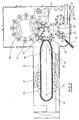
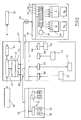
- Fig. 3 shows the basic structure of a Blowing machine, with a heating line (24) and a rotating blowing wheel (25) is provided.
- a heating line (24) Starting from one Preform insert (26) are the preforms (1) of Transfer wheels (27, 28, 29) in the area of the heating section (24) transported.
- Radiant heater (30) and blower (31) arranged to the To temper preforms (1).
- the finished blown containers (2) become from a further transfer wheels a discharge line (32) supplied.
- thermoplastic material can be different Plastics are used. Can be used for example PET, PEN or PP.
- the expansion of the preform (1) during the orientation process done by compressed air supply.
- the Compressed air supply is in a Vorblasphase, in the gas, for example, compressed air, with a low pressure level is fed and in a subsequent Main blowing phase divided, in the gas with a higher Pressure level is supplied.
- the Vorblasphase becomes typically compressed air with a pressure in the interval of 10 bar to 25 bar and during the main blowing phase is compressed air with a pressure in the interval of 25 bar up 40 bar supplied.
- Fig. 3 From Fig. 3 is also seen that in the illustrated embodiment, the heating section (24) a plurality of circulating transport elements (33) is formed, the chain-like strung together and along guide wheels (34) are guided. Especially is thought of by the chain-like arrangement in the réellespannen essential rectangular basic contour. at the illustrated embodiment are in the area of the Transfer wheel (29) and an input wheel (35) facing Extension of the heating section (24) a single relatively large dimensioned deflection wheel (34) and in the range of two adjacent deflections two comparatively smaller dimensioned deflection wheels (36) used. in principle but also any other guides are conceivable.
- the illustrated arrangement proves to be particularly useful, since in the area of the corresponding Extension of the heating section (24) three deflection wheels (34, 36) are positioned, and in each case the smaller ones Deflection wheels (36) in the region of the transition to the linear Course of the heating section (24) and the larger deflection (34) in the immediate transfer area to the transfer wheel (29) and to the input wheel (35).
- chain-like transport elements (33) it is for example also possible to use a rotating heating wheel.
- a larger amount of preforms (1) per unit time be tempered.
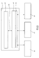
- the blower (31) direct cooling air in the range of cooling air ducts (39), the associated radiant heaters (30) each opposite and Dispense the cooling air via outflow openings.
- the cooling air channels (39) can in the range of the Radiant heaters (30) opposite surfaces Provide reflectors for the heating radiation, also It is also possible to use the discharged cooling air Cooling of the radiant heater (30) to realize.
- Fig. 5 shows the basic principle of the control of a Blowing machine.
- a general Machine control To carry out a general Machine control becomes a central machine control (41) used on the basis of a personal computer realized for general applications.
- the Main components of the central machine control (41) are Plug-in boards (42) for specifiable control components, a visualization (43) and a bus interface (44).
- the internal bus (45) may be, for example, a PCI bus be realized.
- the plug-in boards (42) can be used as a slot PLC or soft PLC can be realized.
- the bus interface (44) is in particular to the Intended use of an OPC bus interface.
- a personal computer can be a PC with one graphical user interface similar to a Windows technology be used.
- Fig. 6 shows in more detail part of the Blowing wheel control (48).
- This control component points a position sensor (49) for detecting a Rotational positioning of the blowing wheel (25).
- the Position sensor (49) for example, on the basis a bar code disc be realized.
- measurement information of the position sensor (49) become relative to each other parallel comparators (50) of an evaluation unit (51) fed.
- the comparators (50) receive in addition to the Measurement information of the position sensor (49) Setpoint information of a setpoint input (52).
- the Setpoint specification (52) is with memory locations for individual Setpoint specifications, for example for a pre-blowing pressure (53), a main blowing pressure (54) and a Blow discharge (55) provided. Saved here each position specifications for the corresponding Pressure connection or pressure dissipation, with the Position information of the position sensor (49) compared become.
- valves (56) are typically called realized electromagnetically controlled valves, so that an electrical switching information with low switching time can be converted into a respective valve position.
- the valves (56) typically have pressure inputs (58). and pressure outputs (59), each with the zu switching components are connected.
- the data for the setpoint specification (52) can be read via the Visualization (43) of the central machine control (41) to be provided.
- a storage to enable a continuous target-actual comparison is done but in Area of the evaluation unit (51) and thus independent from the processing cycle of the central machine control (41).
- the comparators (50) and the output stages (57) can be realized for example as analog components be. Basically, however, is also a digital version possible with high clock frequency.
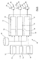
- Fig. 7 shows the structure of the entire control of Blowing machine as a block diagram in a stronger detailed presentation. It is especially noticeable that the central machine control (41) to a Operating data acquisition (60) is connected to the temporal course of a number of operating parameters of Blowing machine detected. In addition, via a modem (61) a connection to a Servicemodem (62) made, the it allows remote diagnosis when occurring Operational disturbances.
- the central machine control (41) is via a electric rotary joint (63), for example as Slip ring assembly may be formed with the Blasrad horrung (48) connected.
- a electric rotary joint for example as Slip ring assembly may be formed with the Blasrad horrung (48) connected.
- contactless couplings for example via an infrared link or via radio transmission, possible.
- the output stages (57) of the evaluation unit (51) are on the valves (56) of the blowing station (3) connected.
- the Blasradmaschineung (48) can also be a control for Servo drives (64) of the stretching rods (11).
- the interface (47) for the machine control is over a bus (65), in particular as a fieldbus may be formed, to the bus interface (44) of the central machine control (41) connected.
- the Interface (47) is equipped with digital inputs (66), digital outputs (67), analog inputs (68) as well as provided with analog outputs (69).
- digital inputs (66) are typically digital reporting members (70) connected to monitoring, the detection of the Machine state and be implemented as a limit switch can.
- the analog inputs (68) are used to connect analog message elements (71), for example as Pyrometer, as pressure transducer, as temperature sensor for used fan, as a temperature sensor for a Cooling water temperature or as a temperature sensor for Heating channels can be formed.
- digital outputs (67) consumers (72) with be connected to digital inputs, for example Valves, displays, relays or contactors.
- digital inputs for example Valves, displays, relays or contactors.
- analog Outputs are used to connect analog actuators (73), for example, for the Vorblastik, the Main blowing pressure, the stretching pressure in pneumatic Stretching systems, the cooling water temperature or the Preform cooling.
- the heating control (46) comprises power parts (74) for Control of the radiant heater (30).
- the radiant heaters can as IR emitters, RF emitters or microwave generators be realized.
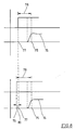
- a starting value (77) in the range of the desired value specification (52) is defined such that taking into account a concrete switching time (78) the pressure value to be reached on Switch-on time (75) is also present.
- the Switching time (78) in the two diagrams shown differ by one valve tolerance (80).
- the respective valve-specific starting values (77) or Correction starting values (79) may be given according to a typical Procedure be determined such that a first Rotation of the blowing wheel with the detection of the valve-specific time delays (78) performed becomes.
- a definition of starting values in the field of Setpoint specification (52) Permanent during operation of the Blowing machine or in cyclic intervals can again one Determination of the individual switching times (78) performed to change, for example, due to a Heating the valves (56) or due to a change to record other operating parameters. It can therefore also a compensation of the switching delays (78) in itself be ensured changing operating parameters.
- Of the entire process can be carried out fully automatically so that for an operator of the machine no additional Operations are required.
- the evaluation unit (51) for specifying the individual Switching times (78) of the valves (56) can be used, for example, as formed a so-called electronic cam switch be. It is also possible to have an interruptible PLC control or another programmable controller use. When using an interruptible PLC controller is used when detecting a degree change in the With regard to the rotational positioning of the blowing wheel the superordinate PLC sequence program interrupted and one Interrupt routine for calculating the switching times (78) the valves (56) activated. In this interrupt routine will be responsible for the speed and accuracy of the Circuit of the valves (56) required functions for Execution of setpoint-actual value comparisons processed.
- interrupt controllers can be very fast cycle times for the comparator functions to be realized in the range of a few microseconds lie.
Landscapes
- Engineering & Computer Science (AREA)
- Manufacturing & Machinery (AREA)
- Mechanical Engineering (AREA)
- Blow-Moulding Or Thermoforming Of Plastics Or The Like (AREA)
- Programmable Controllers (AREA)
- Heating, Cooling, Or Curing Plastics Or The Like In General (AREA)
Abstract
Description
Die Erfindung betrifft ein Verfahren zur Steuerung eines Blasvorganges, bei dem auf einem rotierenden Blasrad angeordneten Blasstationen zur Blasverformung von thermoplastischen Vorformlingen in Behälter mindestens ein unter Druck stehendes Blasfluid zugeführt wird und bei dem mindestens zeitweilig eine aktuelle Rotationspositionierung des Blasrades meßtechnisch erfaßt sowie die entsprechenden Informationen von einer Auswertungseinheit mit Schaltpositionsvorgaben für die Zufuhr und Ableitung des Blasfluids verglichen werden.The invention relates to a method for controlling a Blowing process, in which on a rotating blowing wheel arranged blowing stations for blow molding of thermoplastic preforms in containers at least one pressurized blowing fluid is supplied and in which at least temporarily a current rotational positioning the blowing wheel detected by measurement and the corresponding Information from an evaluation unit with Switching position presets for the supply and discharge of the Blasfluids are compared.
Die Erfindung betrifft darüber hinaus eine Vorrichtung zur Steuerung eines Blasvorganges, die mindestens ein steuerbares Ventil aufweist, das im Bereich einer Zuführleitung für ein Blasfluid angeordnet ist und bei der die Zuführleitung eine Blasfluidversorgung mit mindestens einer Blasstation verbindet, die auf einem rotierenden Blasrad angeordnet ist und die mit einer Meßwerterfassung sowie mit mindestens einem Positionssensor zur Erfassung einer Rotationspositionierung des Blasrades versehen ist sowie bei der die Meßwerterfassung mit einer Auswertungseinheit zur Schaltung der Ventile verbunden ist.The invention further relates to a device for Control of a blowing process, the at least one controllable valve, which is in the range of Supply line is arranged for a blowing fluid and in the the supply line a Blasfluidversorgung with at least a blowing station that connects on a rotating Blasrad is arranged and with a measured value and with at least one position sensor for detection a rotational positioning of the blowing wheel is provided as well as with the measured value acquisition with a Evaluation unit is connected to the circuit of the valves.
Derartige Verfahren und Vorrichtungen werden insbesondere bei der Herstellung von blasgeformten Behältern eingesetzt, um eine mit der Durchführung des Blasvorganges koordinierte Zuleitung eines oder mehrerer Blasdrücke sowie eine Ableitung des Blasdruckes nach einer Ausformung des Behälters durchführen zu können.Such methods and devices are particularly used in the production of blow-molded containers, coordinated with the execution of the blowing process Supply of one or more blowing pressures and a Derivation of the blowing pressure after a formation of the To perform container.
Bei einer derartigen Behälterformung durch Blasdruckeinwirkung werden Vorformlinge aus einem thermoplastischen Material, beispielsweise Vorformlinge aus PET (Polyethylenterephthalat), innerhalb einer Blasmaschine unterschiedlichen Bearbeitungsstationen zugeführt. Typischerweise weist eine derartige Blasmaschine eine Heizeinrichtung sowie eine Blaseinrichtung auf, in deren Bereich der zuvor temperierte Vorformling durch biaxiale Orientierung zu einem Behälter expandiert wird. Die Expansion erfolgt mit Hilfe von Druckluft, die in den zu expandierenden Vorformling eingeleitet wird. Der verfahrenstechnische Ablauf bei einer derartigen Expansion des Vorformlings wird in der DE-OS 43 40 291 erläutert.In such a container molding by Blasdruckeinwirkung be preforms of a thermoplastic material, for example preforms PET (polyethylene terephthalate), within a blow molding machine supplied to different processing stations. Typically, such a blowing machine has a Heating device and a blowing device, in whose Area of previously tempered preform by biaxial Orientation is expanded to a container. The Expansion takes place with the help of compressed air in the too expanding preform is initiated. Of the procedural sequence in such an expansion of the preform is explained in DE-OS 43 40 291.
Der grundsätzliche Aufbau einer Blasstation zur Behälterformung wird in der DE-OS 42 12 583 beschrieben. Möglichkeiten zur Temperierung der Vorformlinge werden in der DE-OS 23 52 926 erläutert.The basic structure of a blowing station for Container molding is described in DE-OS 42 12 583. Possibilities for tempering the preforms are in DE-OS 23 52 926 explained.
Innerhalb der Vorrichtung zur Blasformung können die Vorformlinge sowie die geblasenen Behälter mit Hilfe unterschiedlicher Handhabungseinrichtungen transportiert werden. Bewährt hat sich insbesondere die Verwendung von Transportdornen, auf die die Vorformlinge aufgesteckt werden. Die Vorformlinge können aber auch mit anderen Trageinrichtungen gehandhabt werden. Die Verwendung von Greifzangen zur Handhabung von Vorformlingen und die Verwendung von Spreizdornen, die zur Halterung in einen Mündungsbereich des Vorformlings einführbar sind, gehören ebenfalls zu den verfügbaren Konstruktionen.Within the blow molding apparatus, the Preforms as well as the blown containers with the help transported different handling equipment become. Has proven particularly the use of Transport mandrels on which the preforms are attached become. The preforms can also be used with others Carrying facilities are handled. The usage of Tongs for handling preforms and the Use of expanding mandrels for mounting in a Mouth region of the preform are insertable belong also to the available constructions.
Die bereits erläuterte Handhabung der Vorformlinge erfolgt zum einen bei den sogenannten Zweistufenverfahren, bei denen die Vorformlinge zunächst in einem Spritzgußverfahren hergestellt, anschließend zwischengelagert und erst später hinsichtlich ihrer Temperatur konditioniert und zu einem Behälter aufgeblasen werden. Zum anderen erfolgt eine Anwendung bei den sogenannten Einstufenverfahren, bei denen die Vorformlinge unmittelbar nach ihrer spritzgußtechnischen Herstellung und einer ausreichenden Verfestigung geeignet temperiert und anschließend aufgeblasen werden.The already explained handling of the preforms takes place on the one hand in the so-called two-stage process, in which the preforms initially in an injection molding process produced, then stored temporarily and later conditioned in terms of their temperature and to a Be inflated container. On the other hand, there is a Application in the so-called one-step process, in which the preforms immediately after their injection molding production and a sufficient Solidification suitable tempered and then be inflated.
Im Hinblick auf die verwendeten Blasstationen sind unterschiedliche Ausführungsformen bekannt. Bei Blasstationen, die auf rotierenden Transporträdern angeordnet sind, ist eine buchartige Aufklappbarkeit der Formträger häufig anzutreffen. Es ist aber auch möglich, relativ zueinander verschiebliche oder andersartig geführte Formträger einzusetzen. Bei Blasstationen, die insbesondere dafür geeignet sind, mehrere Kavitäten zur Behälterformung aufzunehmen, werden neben aufklappbaren Formen auch parallel zueinander angeordnete Platten als Formträger verwendet. With regard to the blowing stations used different embodiments known. at Blowing stations on rotating transport wheels arranged, is a book - like Aufklappbarkeit the Mold carrier frequently encountered. But it is also possible relative to each other displaceable or otherwise guided Insert mold carrier. In blow molding stations, in particular are suitable for several cavities for container molding Also, next to hinged forms are included parallel plates arranged as a mold carrier used.
Im Hinblick auf die ständig zunehmenden Produktionsgeschwindigkeiten bei der Herstellung von Behältern, die zur Zeit durch eine Leistungsfähigkeit von etwa 1650 Flaschen je Blasstation und Stunde charakterisiert sind, erweist sich eine exakte und reproduzierbare Ansteuerung der Ventile für die Blasluft als ein entscheidendes Kriterium für die Herstellung qualitativ hochwertiger Behälter. Insbesondere zeigt es sich, daß beim Einsatz von zentralen Maschinensteuerungen durch die hier vorgegebene Taktung unter zusätzlicher Berücksichtigung von Schaltverzögerungen der Ventile sowie unter Berücksichtigung von auftretenden Toleranzen bereits das Zusammenwirken dieser Faktoren zu deutlich erkennbaren Schwankungen in der Materialverteilung der blasgeformten Behälter führt.With regard to the ever-increasing Production speeds in the production of Containers currently under a performance of about 1650 bottles per blowing station and hour are characterized, proves to be an exact and reproducible control of the valves for the blown air as a crucial criterion for the production high quality container. In particular, it shows itself, that when using central machine controls by the here specified clocking under additional Consideration of switching delays of the valves as well taking into account occurring tolerances already the interaction of these factors to clearly recognizable Fluctuations in the material distribution of the blow-molded Container leads.
Aufgabe der vorliegenden Erfindung ist es daher, ein Verfahren der einleitend genannten Art derart anzugeben, daß eine verbesserte Ansteuerung der Ventile erreicht werden kann.Object of the present invention is therefore, a Specify method of the type mentioned in the introduction that achieved an improved control of the valves can be.
Diese Aufgabe wird erfindungsgemäß dadurch gelöst, die Auswertungseinheit unabhängig von einem Bearbeitungszyklus einer zentralen Maschinensteuerung betrieben wird, daß mindestens zwei Vergleichern der Auswertungseinheit, die Sollwerte für die Ventilsteuerung mit Istwerten aus den Meßinformationen verknüpfen, die Meßinformationen relativ zueinander parallel und gleichzeitig zugeführt werden und daß die Vergleicher über Ausgangsstufen direkt auf die Ventile einwirken.This object is achieved by the, Evaluation unit independent of a processing cycle a central machine control is operated that at least two comparators of the evaluation unit, the Setpoints for the valve control with actual values from the Link measurement information, the measurement information relative be fed to each other in parallel and simultaneously and that the comparators via output stages directly to the Acting valves.
Weitere Aufgabe der vorliegenden Erfindung ist es, eine Vorrichtung der einleitend genannten Art derart zu konstruieren, daß die Herstellung von Behältern mit relativ zueinander identischen Materialverteilungen unterstützt wird.Another object of the present invention is to provide a Device of the type mentioned in the introduction to such Construct that the production of containers with relative supports mutually identical material distributions becomes.
Diese Aufgabe wird erfindungsgemäß dadurch gelöst, daß die Auswertungseinheit eine von einem Arbeitszyklus einer zentralen Maschinensteuerung unabhängige Arbeitsweise aufweist, daß die Auswertungseinheit mit mindestens zwei Vergleichern zur Verknüpfung von Ist-Signalen des Positionssensors und Sollwertvorgaben versehen ist, daß die Vergleicher relativ zueinander parallel an den Positionssensor angeschlossen sind und daß die Auswertungseinheit über Ausgangsstufen direkt mit den Ventilen verbunden ist.This object is achieved in that the Evaluation unit one of a working cycle one central machine control independent operation has, that the evaluation unit with at least two Comparishers for linking actual signals of the Position sensors and setpoint specifications is provided that the Comparator relative to each other in parallel to the Position sensor are connected and that the Evaluation unit via output stages directly with the Valves is connected.
Durch den Betrieb der Auswertungseinheit unabhängig vom Arbeitszyklus der zentralen Maschinensteuerung ist eine verzögerungsfreie bzw. zumindest verzögerungsarme Ansteuerung der Ventile möglich. Insbesondere wird auch eine sehr große Reproduktionsgenauigkeit bei mehreren aufeinander folgenden Ansteuerungen erreicht. Bei einer Verarbeitung der Meßsignale über die zentrale Maschinensteuerung vergehen im ungünstigem Fall zwei Bearbeitungszyklen, bis die anliegenden Meßinformationen ausgewertet und entsprechende Steuersignale zu den Ventilen übermittelt wurden. Bei einer von der zentralen Maschinensteuerung unabhängigen Verarbeitung entsteht lediglich eine Verzögerung, die durch die reine Verarbeitungszeit sowie entsprechende Schaltverzögerungen der Ventile verursacht wird. Bei bekannten Schaltverzögerungen der Ventile kann diese Verzögerungszeit durch eine entsprechende Vorverlegung des Ansteuerzeitpunktes auch noch kompensiert werden.By the operation of the evaluation unit independent of Cycle of the central machine control is one delay-free or at least low-delay Control of the valves possible. In particular, too a very high reproduction accuracy for several achieved successive controls. At a Processing of the measuring signals via the central Machine control pass two in the worst case Processing cycles, until the applied measurement information evaluated and appropriate control signals to the valves were transmitted. At one of the central Machine control independent processing arises only a delay, by pure Processing time and corresponding switching delays the valves is caused. At acquaintances Switching delays of the valves can this delay time by an appropriate advance of the Ansteuerzeitpunktes also be compensated.
Bei einer typischen Konstruktion sind auf einem Blasrad eine Mehrzahl von Blasstationen angeordnet, denen jeweils mehrere Ventile zugeordnet sind. Durch einen parallelen Anschluß aller Vergleicher an den Positionssensor wird unabhängig von den Schaltaktivitäten benachbarter Ventile oder benachbarter Blasstationen eine unmittelbare Aktivierung des jeweils betroffenen Ventils ermöglicht. Die direkte Kopplung der Auswertungseinheit über die Ausgangsstufen mit den Ventilen trägt ebenfalls zu einer kurzen resultierenden Schaltzeit bei.In a typical design are on a blowing wheel a plurality of blowing stations arranged, each one several valves are assigned. Through a parallel Connection of all comparators to the position sensor is regardless of the switching activities of adjacent valves or neighboring blowing stations an immediate Activation of each affected valve allows. The direct coupling of the evaluation unit over the Output stages with the valves also contributes to one short resulting switching time at.
Eine einfache Bedienungsstruktur wird dadurch bereitgestellt, daß die Auswertungseinheit über eine Datenschnittstelle mit der zentralen Maschinensteuerung gekoppelt wird.A simple operating structure is thereby provided that the evaluation unit via a Data interface with the central machine control is coupled.
Zur Unterstützung einer individuellen Einstellung in Abhängigkeit von der Gestaltung jeweils herzustellender Behälter wird vorgeschlagen, daß von der zentralen Maschinensteuerung Sollwerte zur Auswertungseinheit übertragen werden.To support an individual setting in Depending on the design to be produced in each case Container is suggested that from the central Machine control setpoints for the evaluation unit be transmitted.
Eine Herstellung von Behältern mit relativ zueinander gleichmäßigen Materialverteilungen wird insbesondere dadurch erreicht, daß unterschiedlichen Ventilen unterschiedliche Sollwerte für eine jeweilige Ansteuerung zugeordnet werden.A production of containers with relative to each other even material distributions become particular achieved in that different valves different setpoints for a particular control be assigned.
Eine Adaption an konkrete Betriebsparameter erfolgt dadurch, daß die Sollwerte für die Ansteuerung der Ventile für jedes Ventil individuell ermittelt werden.An adaptation to concrete operating parameters takes place in that the setpoint values for the control of the valves be determined individually for each valve.
Ein vorteilhafter Steuerungsablauf besteht darin, daß vor einer Produktionsaufnahme das Blasrad mindestens einen Umlauf zur Ermittlung der Schaltsollwerte für die Ventile durchführt.An advantageous control sequence is that before a production start the blowing wheel at least one Circulation to determine the setpoint switching values for the valves performs.
Zur Gewährleistung einer Berücksichtigung von sich zeitlich ändernden Parametern wird vorgeschlagen, daß bei einem Betrieb des Blasrades kontinuierlich aktuelle Schaltsollwerte für die Ventile unter Berücksichtigung von gemessenen Schaltverzögerungen ermittelt werden.To ensure consideration of time changing parameters is proposed that at a Operation of the blowing wheel continuously current Switching setpoints for the valves taking into account measured switching delays are determined.
Ebenfalls ist daran gedacht, daß eine Adaption von Schaltsollwerten für die Ventile zu vorgebbaren Abgleichzeitpunkten durchgeführt wird.It is also thought that an adaptation of Switching setpoints for the valves to be specified Matching times is performed.
Eine preiswerte und zugleich flexible Steuerung wird dadurch bereitgestellt, daß eine Sollwertvorgabe für die Schaltzeitpunkte der Ventile unter Verwendung eines Personal-Computers durchgeführt wird.An inexpensive and at the same time flexible control becomes provided by a setpoint input for the Switching times of the valves using a Personal computer is performed.
Zur Unterstützung einer Anpassung an unterschiedliche Anwendungsanforderungen wird vorgeschlagen, daß eine Systemsteuerung unter Verwendung eines Personal-Computers mit Einschüben zur Realisierung einer speicherprogrammierbaren Steuerung durchgeführt wird. Dies kann beispielsweise durch die Verwendung einer sogenannten Slot-SPS oder Soft-SPS erfolgen. Bei einer Soft-SPS erfolgt die Steuerung durch Software, die auf dem Personal-Computer abläuft.To support an adaptation to different Application requirements are suggested that a Control panel using a personal computer with inserts for the realization of a programmable controller is performed. This For example, by the use of a so-called Slot PLC or Soft PLC done. For a soft PLC the control by software on the personal computer expires.
Eine sehr einfache Bedienbarkeit wird dadurch unterstützt, daß die zentrale Maschinensteuerung eine Visualisierung aufweist. A very simple operability is supported, that the central machine control a visualization having.
Eine zweckmäßige Bedienungsstruktur wird dadurch bereitgestellt, daß die zentrale Maschinensteuerung Ausgänge zur Übermittlung von Sollwerten für die Druckzuführung zu den Blasstationen über die Ventile aufweist.A convenient operating structure is thereby provided that the central machine control Outputs for the transmission of setpoints for the Pressure supply to the blowing stations via the valves having.
Ebenfalls ist daran gedacht, daß die zentrale Maschinensteuerung Ausgänge zur Übermittlung von Sollwerten für die Druckableitung zu den Blasstationen über die Ventile aufweist.It is also thought that the central Machine control outputs for the transmission of setpoints for the pressure discharge to the blow molding stations over the Has valves.
Eine modulare Systemstruktur wird auch dadurch unterstützt, daß Schaltpositionsvorgaben für die Auswertungseinheit von mindestens einem Modul der speicherprogrammierbaren Steuerung der zentralen Maschinensteuerung vorgegeben sind. Alternativ ist es auch möglich, daß die Schaltpositionsvorgaben von einer Verarbeitungseinheit im Bereich des Blasrades vorgegeben werden.A modular system structure is also supported by that switching position specifications for the evaluation unit of at least one module of the programmable logic controller Control of the central machine control are given. Alternatively, it is also possible that the Switching position specifications from a processing unit in the Area of the blowing wheel can be specified.
Zur Vorgabe von optimalen Steuerwinkeln während des Prozeßablaufes wird vorgeschlagen, daß unterschiedliche Steuerwinkel für die Druckversorgung jeder Blasstation im Hinblick auf einen Vorblasdruck, einen Hauptblasdruck und eine Druckableitung vorgesehen sind.To specify optimal control angles during the Process flow is proposed that different Control angle for the pressure supply of each blow station in With regard to a Vorblasdruck, a main blowing pressure and a pressure discharge are provided.
Eine weitere vorteilhafte konstruktive Realisierung besteht darin, daß die zentrale Maschinensteuerung sowohl mit analogen Eingängen als auch mit analogen Ausgängen verbunden ist. Another advantageous constructive realization exists in that the central machine control with both analog inputs as well as with analog outputs connected is.
Darüber hinaus erweist es sich als zweckmäßig, daß die zentrale Maschinensteuerung sowohl mit digitalen Eingängen als auch mit digitalen Ausgängen verbunden ist.In addition, it proves to be appropriate that the Central machine control with both digital inputs as well as with digital outputs.
Zur Unterstützung einer schnellen Erkennung von Störungen wird vorgeschlagen, daß die Auswertungseinheit mit einem Ausgang zur Übermittlung von Fehlermeldungen an die zentrale Maschinensteuerung versehen ist.To support a quick detection of interference It is proposed that the evaluation unit with a Output for the transmission of error messages to the central machine control is provided.
Eine weitgehende Funktionsentkopplung zwischen der Auswertungseinheit und der zentralen Maschinensteuerung wird dadurch realisiert, daß die Auswertungseinheit einen Speicher für die Schaltpositionsvorgaben aufweist.A substantial function decoupling between the Evaluation unit and the central machine control is realized in that the evaluation unit a Memory for the shift position specifications has.
Ein schneller Datenaustausch wird dadurch unterstützt, daß die zentrale Maschinensteuerung über einen Bus mit der Auswertungseinheit verbunden ist.A fast data exchange is supported by the fact that the central machine control via a bus with the Evaluation unit is connected.
Zur Unterstützung von Ferndiagnosen wird vorgeschlagen, daß die zentrale Maschinensteuerung mit einem Modem zur Datenübertragung ausgestattet ist.In support of remote diagnostics it is suggested that the central machine control with a modem for Data transmission is equipped.
Eine sehr flexible Steuerungsstruktur wird auch dadurch unterstützt, daß die speicherprogrammierbare Steuerung der zentralen Maschinensteuerung über eine OPC-Schnittstelle an das Bus-System angeschlossen ist.A very flexible control structure is also characterized supports that the programmable logic controller of the central machine control via an OPC interface the bus system is connected.
Zur Unterstützung eines Datenaustausches mit dem rotierenden Blasrad wird vorgeschlagen, daß das Bus-System über mindestens eine elektrische Drehkupplung mit der Auswertungseinheit verbunden ist. Dies kann beispielsweise in der Form eines Drehverteilers mit Schleifring erfolgen. Alternativ ist auch die Verwendung einer Opto-Elektronik oder einer Funkstrecke möglich.To support a data exchange with the Rotating blowing wheel is suggested that the bus system via at least one electric rotary coupling with the Evaluation unit is connected. This can be, for example in the form of a rotary distributor with slip ring. Alternatively, the use of opto-electronics or a radio link possible.
Eine digitale Verarbeitung wird dadurch unterstützt, daß der Positionssensor einen Generator für positionsabhängige Zählimpulse aufweist.Digital processing is supported by the position sensor is a position-dependent generator Counting has.
Zur Gewährleistung einer optimalen Kapazitätsausnutzung der Maschinensteuerung wird vorgeschlagen, daß die zentrale Maschinensteuerung eine interne Ablaufsteuerung aufweist, die mit unterschiedlichen Ansprechhäufigkeiten für unterschiedliche Steuerungsfunktionen versehen ist und bei der eine Heizungssteuerung relativ zu einer Blasradsteuerung mit einer geringeren Ansprechhäufigkeit und eine Ventilsteuerung relativ zu einer Blasradsteuerung mit höherer Ansprechhäufigkeit versehen ist. Eine derartige Betriebsweise kann über eine sogenannte Multitasking-Ablauf steuerung erreicht werden.To ensure optimum capacity utilization of the Machine control is proposed that the central Machine control has an internal flow control, those with different response frequencies for different control functions is provided and at a heating control relative to a Blower wheel control with a lower response frequency and a valve control relative to a Blasradsteuerung is provided with a higher response frequency. Such Operation can be via a so-called multitasking process be achieved.
Eine einfache Anschließbarkeit für unterschiedliche Funktionsbaugruppen wird dadurch bereitgestellt, daß die zentrale Maschinensteuerung mindestens ein offenes Bus-System aufweist.A simple connectivity for different Functional assemblies are provided by the fact that the central machine control at least one open bus system having.
Insbesondere ist daran gedacht, daß die zentrale Maschinensteuerung mit mindestens einem Feldbus-System versehen ist.In particular, it is thought that the central Machine control with at least one fieldbus system is provided.
Eine Übertragung von großen Datenmengen wird dadurch erleichtert, daß die Visualisierung der zentralen Maschinensteuerung über einen PCI-Bus mit der speicherprogrammierbaren Steuerung verbunden ist. Alternativ ist auch eine Verbindung zwischen der Visualisierung und der bereits erwähnten Slot-SPS oder Soft-SPS möglich.A transmission of large amounts of data is thereby facilitates the visualization of the central Machine control via a PCI bus with the Programmable logic controller is connected. Alternatively, a connection between the Visualization and the already mentioned slot PLC or Soft PLC possible.
In den Zeichnungen sind Ausführungsbeispiele der Erfindung schematisch dargestellt. Es zeigen:
- Fig. 1
- Eine perspektivische Darstellung einer Blasstation zur Herstellung von Behältern aus Vorformlingen,
- Fig. 2
- einen Längsschnitt durch eine Blasform, in der ein Vorformling gereckt und expandiert wird,
- Fig. 3
- eine Skizze zur Veranschaulichung eines grundsätzlichen Aufbaus einer Vorrichtung zur Blasformung von Behältern,
- Fig. 4
- eine modifizierte Heizstrecke mit vergrößerter Heizkapazität,
- Fig. 5
- ein stark vereinfachtes Blockschaltbild zur Veranschaulichung des Steuerungskonzeptes der gesamten Blasmaschine,
- Fig. 6
- ein Blockschaltbild zur Veranschaulichung der Ventilsteuerung,
- Fig. 7
- ein detaillierteres Blockschaltbild zur gesamten Maschinensteuerung und
- Fig. 8
- Zeitdiagramme zur Veranschaulichung einer Kompensation von unterschiedlichen Ventilschaltzeiten.
- Fig. 1
- A perspective view of a blowing station for the production of containers from preforms,
- Fig. 2
- a longitudinal section through a blow mold, in which a preform is stretched and expanded,
- Fig. 3
- a sketch to illustrate a basic structure of a device for blow molding containers,
- Fig. 4
- a modified heating section with increased heating capacity,
- Fig. 5
- a highly simplified block diagram for illustrating the control concept of the entire blow molding machine,
- Fig. 6
- a block diagram illustrating the valve control,
- Fig. 7
- a more detailed block diagram for the entire machine control and
- Fig. 8
- Timing diagrams to illustrate a compensation of different valve switching times.
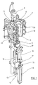
Eine Anwendung des Verfahrens und der Vorrichtung zur Steuerung des Blasvorganges kann beispielsweise zur Steuerung der Blasluftzuführung bei einer Vorrichtung zur Blasformung erfolgen. Der prinzipielle Aufbau einer Vorrichtung zur Umformung von Vorformlingen (1) in Behälter (2) ist in Fig. 1 und in Fig. 2 dargestellt.An application of the method and the device for Control of the blowing process, for example, the Control of the blast air supply in a device for Blow molding done. The basic structure of a Apparatus for forming preforms (1) into containers (2) is shown in Fig. 1 and in Fig. 2.
Die Vorrichtung zur Formung des Behälters (2) besteht im wesentlichen aus einer Blasstation (3), die mit einer Blasform (4) versehen ist, in die ein Vorformling (1) einsetzbar ist. Der Vorformling (1) kann ein spritzgegossenes Teil aus Polyethylenterephthalat sein. Zur Ermöglichung eines Einsetzens des Vorformlings (1) in die Blasform (4) und zur Ermöglichung eines Herausnehmens des fertigen Behälters (2) besteht die Blasform (4) aus Formhälften (5, 6) und einem Bodenteil (7), das von einer Hubvorrichtung (8) positionierbar ist. Der Vorformling (1) kann im Bereich der Blasstation (3) von einem Transportdorn (9) gehalten sein, der gemeinsam mit dem Vorformling (1) eine Mehrzahl von Behandlungsstationen innerhalb der Vorrichtung durchläuft. Es ist aber auch möglich, den Vorformling (1) beispielsweise über Zangen oder andere Handhabungsmittel direkt in die Blasform (4) einzusetzen.The device for forming the container (2) consists in Substantially from a blowing station (3), which with a Blow mold (4) into which a preform (1) can be used. The preform (1) can be injection-molded part of polyethylene terephthalate be. to Enabling insertion of the preform (1) in the Blow mold (4) and to enable removal of the finished container (2) consists of the blow mold (4) Mold halves (5, 6) and a bottom part (7) of a Lifting device (8) is positionable. The preform (1) can in the area of blow station (3) from a transport mandrel (9), which together with the preform (1) a plurality of treatment stations within the Device undergoes. But it is also possible, the Preform (1) for example via pliers or others Use handling agent directly in the blow mold (4).
Zur Ermöglichung einer Druckluftzuleitung ist unterhalb des Transportdornes (9) ein Anschlußkolben (10) angeordnet, der dem Vorformling (1) Druckluft zuführt und gleichzeitig eine Abdichtung relativ zum Transportdorn (9) vornimmt. Bei einer abgewandelten Konstruktion ist es grundsätzlich aber auch denkbar, feste Druckluftzuleitungen zu verwenden. To enable a compressed air supply line is below the transport mandrel (9) a connecting piston (10) arranged which supplies compressed air to the preform (1) and at the same time a seal relative to the transport mandrel (9) makes. In a modified construction, it is basically but also conceivable to use solid compressed air supply lines.
Eine Reckung des Vorformlings (1) erfolgt mit Hilfe einer Reckstange (11), die von einem Zylinder (12) positioniert wird. Grundsätzlich ist es aber auch denkbar, eine mechanische Positionierung der Reckstange (11) über Kurvensegmente durchzuführen, die von Abgriffrollen beaufschlagt sind. Die Verwendung von Kurvensegmenten ist insbesondere dann zweckmäßig, wenn eine Mehrzahl von Blasstationen (3) auf einem rotierenden Blasrad angeordnet sind. Eine Verwendung von Zylindern (12) ist zweckmäßig, wenn ortsfest angeordnete Blasstationen (3) vorgesehen sind.A stretching of the preform (1) takes place with the aid of a Stretching bar (11), positioned by a cylinder (12) becomes. Basically, it is also conceivable, a mechanical positioning of the stretch rod (11) over Curve segments to perform by Abgriffrollen are charged. The use of curve segments is especially useful when a plurality of Blowing stations (3) arranged on a rotating blowing wheel are. A use of cylinders (12) is appropriate if stationarily arranged blowing stations (3) provided are.
Bei der in Fig. 1 dargestellten Ausführungsform ist das Recksystem derart ausgebildet, daß eine Tandem-Anordnung von zwei Zylindern (12) bereitgestellt ist. Von einem Primärzylinder (13) wird die Reckstange (11) zunächst vor Beginn des eigentlichen Reckvorganges bis in den Bereich eines Bodens (14) des Vorformlings (1) gefahren. Während des eigentlichen Reckvorganges wird der Primärzylinder (13) mit ausgefahrener Reckstange gemeinsam mit einem den Primärzylinder (13) tragenden Schlitten (15) von einem Sekundärzylinder (16) oder über eine Kurvensteuerung positioniert. Insbesondere ist daran gedacht, den Sekundärzylinder (16) derart kurvengesteuert einzusetzen, daß von einer Führungsrolle (17), die während der Durchführung des Reckvorganges an einer Kurvenbahn entlang gleitet, eine aktuelle Reckposition vorgegeben wird. Die Führungsrolle (17) wird vom Sekundärzylinder (16) gegen die Führungsbahn gedrückt. Der Schlitten (15) gleitet entlang von zwei Führungselementen (18).In the embodiment shown in Fig. 1 is the Stretching system designed such that a tandem arrangement of two cylinders (12) is provided. Of a Primary cylinder (13), the stretch rod (11) before Beginning of the actual stretching process up to the area a bottom (14) of the preform (1) driven. While the actual stretching process, the primary cylinder (13) with extended stretch rod together with a Primary cylinder (13) carrying carriage (15) of a Secondary cylinder (16) or via a cam control positioned. In particular, it is thought that the Use secondary cylinder (16) in a cam-controlled manner, that of a guide roller (17) during the Carrying out the stretching process along a curved path slides, a current stretching position is specified. The Guide roller (17) is from the secondary cylinder (16) against the Guideway pressed. The carriage (15) slides along of two guide elements (18).
Nach einem Schließen der im Bereich von Trägern (19, 20) angeordneten Formhälften (5, 6) erfolgt eine Verriegelung der Träger (19, 20) relativ zueinander mit Hilfe einer Verriegelungseinrichtung (20). After closing in the region of carriers (19, 20) arranged mold halves (5, 6) takes place a lock the carrier (19, 20) relative to each other by means of a Locking device (20).
Zur Anpassung an unterschiedliche Formen eines Mündungsabschnittes (21) des Vorformlings (1) ist gemäß Fig. 2 die Verwendung separater Gewindeeinsätze (22) im Bereich der Blasform (4) vorgesehen.To adapt to different shapes of a mouth section (21) of the preform (1) is shown in FIG. 2 the Use of separate thread inserts (22) in the area of Blow mold (4) provided.
Fig. 2 zeigt zusätzlich zum geblasenen Behälter (2) auch gestrichelt eingezeichnet den Vorformling (1) und schematisch eine sich entwickelnde Behälterblase (23).Fig. 2 shows in addition to the blown container (2) also Dashed lines drawn the preform (1) and schematically a developing container bladder (23).
Fig. 3 zeigt den grundsätzlichen Aufbau einer Blasmaschine, die mit einer Heizstrecke (24) sowie einem rotierenden Blasrad (25) versehen ist. Ausgehend von einer Vorformlingseingabe (26) werden die Vorformlinge (1) von Übergaberädern (27, 28, 29) in den Bereich der Heizstrecke (24) transportiert. Entlang der Heizstrecke (24) sind Heizstrahler (30) sowie Gebläse (31) angeordnet, um die Vorformlinge (1) zu temperieren. Nach einer ausreichenden Temperierung der Vorformlinge (1) werden diese an das Blasrad (25) übergeben, in dessen Bereich die Blasstationen (3) angeordnet sind. Die fertig geblasenen Behälter (2) werden von weiteren Übergaberädern einer Ausgabestrecke (32) zugeführt.Fig. 3 shows the basic structure of a Blowing machine, with a heating line (24) and a rotating blowing wheel (25) is provided. Starting from one Preform insert (26) are the preforms (1) of Transfer wheels (27, 28, 29) in the area of the heating section (24) transported. Along the heating line (24) are Radiant heater (30) and blower (31) arranged to the To temper preforms (1). After a sufficient Temperierung of the preforms (1) are these to the Blowing wheel (25) handed over, in the area of the blowing stations (3) are arranged. The finished blown containers (2) become from a further transfer wheels a discharge line (32) supplied.
Um einen Vorformling (1) derart in einen Behälter (2) umformen zu können, daß der Behälter (2) Materialeigenschaften aufweist, die eine lange Verwendungsfähigkeit von innerhalb des Behälters (2) abgefüllten Lebensmitteln, insbesondere von Getränken, gewährleisten, müssen spezielle Verfahrensschritte bei der Beheizung und Orientierung der Vorformlinge (1) eingehalten werden. Darüber hinaus können vorteilhafte Wirkungen durch Einhaltung spezieller Dimensionierungsvorschriften erzielt werden. To a preform (1) in such a container (2) to transform that the container (2) Has material properties that last a long time Usefulness of within the container (2) bottled foods, in particular drinks, must ensure special process steps in the Heating and orientation of the preforms (1) complied with become. In addition, beneficial effects can be achieved by Compliance with special dimensioning rules achieved become.
Als thermoplastisches Material können unterschiedliche Kunststoffe verwendet werden. Einsatzfähig sind beispielsweise PET, PEN oder PP.As thermoplastic material can be different Plastics are used. Can be used for example PET, PEN or PP.
Die Expansion des Vorformlings (1) während des Orientierungsvorganges erfolgt durch Druckluftzuführung. Die Druckluftzuführung ist in eine Vorblasphase, in der Gas, zum Beispiel Preßluft, mit einem niedrigen Druckniveau zugeführt wird und in eine sich anschließende Hauptblasphase unterteilt, in der Gas mit einem höheren Druckniveau zugeführt wird. Während der Vorblasphase wird typischerweise Druckluft mit einem Druck im Intervall von 10 bar bis 25 bar verwendet und während der Hauptblasphase wird Druckluft mit einem Druck im Intervall von 25 bar bis 40 bar zugeführt.The expansion of the preform (1) during the orientation process done by compressed air supply. The Compressed air supply is in a Vorblasphase, in the gas, for example, compressed air, with a low pressure level is fed and in a subsequent Main blowing phase divided, in the gas with a higher Pressure level is supplied. During the Vorblasphase becomes typically compressed air with a pressure in the interval of 10 bar to 25 bar and during the main blowing phase is compressed air with a pressure in the interval of 25 bar up 40 bar supplied.
Aus Fig. 3 ist ebenfalls erkennbar, daß bei der dargestellten Ausführungsform die Heizstrecke (24) aus einer Vielzahl umlaufender Transportelemente (33) ausgebildet ist, die kettenartig aneinandergereiht und entlang von Umlenkrädern (34) geführt sind. Insbesondere ist daran gedacht, durch die kettenartige Anordnung eine im wesentlichen rechteckförmige Grundkontur aufzuspannen. Bei der dargestellten Ausführungsform werden im Bereich der dem Übergaberad (29) und einem Eingaberad (35) zugewandten Ausdehnung der Heizstrecke (24) ein einzelnes relativ groß dimensioniertes Umlenkrad (34) und im Bereich von benachbarten Umlenkungen zwei vergleichsweise kleiner dimensionierte Umlenkräder (36) verwendet. Grundsätzlich sind aber auch beliebige andere Führungen denkbar.From Fig. 3 is also seen that in the illustrated embodiment, the heating section (24) a plurality of circulating transport elements (33) is formed, the chain-like strung together and along guide wheels (34) are guided. Especially is thought of by the chain-like arrangement in the aufzuspannen essential rectangular basic contour. at the illustrated embodiment are in the area of the Transfer wheel (29) and an input wheel (35) facing Extension of the heating section (24) a single relatively large dimensioned deflection wheel (34) and in the range of two adjacent deflections two comparatively smaller dimensioned deflection wheels (36) used. in principle but also any other guides are conceivable.
Zur Ermöglichung einer möglichst dichten Anordnung des Übergaberades (29) und des Eingaberades (35) relativ zueinander erweist sich die dargestellte Anordnung als besonders zweckmäßig, da im Bereich der entsprechenden Ausdehnung der Heizstrecke (24) drei Umlenkräder (34, 36) positioniert sind, und zwar jeweils die kleineren Umlenkräder (36) im Bereich der Überleitung zu den linearen Verläufen der Heizstrecke (24) und das größere Umlenkrad (34) im unmittelbaren Übergabebereich zum Übergaberad (29) und zum Eingaberad (35). Alternativ zur Verwendung von kettenartigen Transportelementen (33) ist es beispielsweise auch möglich, ein rotierendes Heizrad zu verwenden.To enable a dense arrangement of the Transfer wheel (29) and the input wheel (35) relative to each other, the illustrated arrangement proves to be particularly useful, since in the area of the corresponding Extension of the heating section (24) three deflection wheels (34, 36) are positioned, and in each case the smaller ones Deflection wheels (36) in the region of the transition to the linear Course of the heating section (24) and the larger deflection (34) in the immediate transfer area to the transfer wheel (29) and to the input wheel (35). Alternatively to using chain-like transport elements (33) it is for example also possible to use a rotating heating wheel.
Nach einem fertigen Blasen der Behälter (2) werden diese von einem Entnahmerad (37) aus dem Bereich der Blasstationen (3) herausgeführt und über das Übergaberad (28) und ein Ausgaberad (38) zur Ausgabestrecke (32) transportiert.After a finished blowing of the container (2) they are from a removal wheel (37) from the field of Blowing stations (3) led out and over the transfer wheel (28) and an output wheel (38) to the output path (32) transported.
In der in Fig. 4 dargestellten modifizierten Heizstrecke (24) können durch die größere Anzahl von Heizstrahlern (30) eine größere Menge von Vorformlingen (1) je Zeiteinheit temperiert werden. Die Gebläse (31) leiten hier Kühlluft in den Bereich von Kühlluftkanälen (39) ein, die den zugeordneten Heizstrahlern (30) jeweils gegenüberliegen und über Ausströmöffnungen die Kühlluft abgeben. Durch die Anordnung der Ausströmrichtungen wird eine Strömungsrichtung für die Kühlluft im wesentlichen quer zu einer Transportrichtung der Vorformlinge (1) realisiert. Die Kühlluftkanäle (39) können im Bereich von den Heizstrahlern (30) gegenüberliegenden Oberflächen Reflektoren für die Heizstrahlung bereitstellen, ebenfalls ist es möglich, über die abgegebene Kühlluft auch eine Kühlung der Heizstrahler (30) zu realisieren.In the modified heating section shown in Fig. 4 (24) may be affected by the larger number of radiant heaters (30) a larger amount of preforms (1) per unit time be tempered. The blower (31) direct cooling air in the range of cooling air ducts (39), the associated radiant heaters (30) each opposite and Dispense the cooling air via outflow openings. By the Arrangement of Ausströmrichtungen is a Flow direction for the cooling air substantially transverse to a transport direction of the preforms (1) realized. The cooling air channels (39) can in the range of the Radiant heaters (30) opposite surfaces Provide reflectors for the heating radiation, also It is also possible to use the discharged cooling air Cooling of the radiant heater (30) to realize.
Fig. 5 zeigt das Grundprinzip der Steuerung einer Blasmaschine. Zur Durchführung einer allgemeinen Maschinensteuerung wird eine zentrale Maschinensteuerung (41) verwendet, die auf der Basis eines Personal-Computers für allgemeine Anwendungen realisiert ist. Die Hauptkomponenten der zentralen Maschinensteuerung (41) sind Einschubplatinen (42) für vorgebbare Steuerungskomponenten, eine Visualisierung (43) sowie eine Busschnittstelle (44). Eine Kopplung der Visualisierung (43) mit den Einschubplatinen (42) erfolgt über einen internen Bus (45).Fig. 5 shows the basic principle of the control of a Blowing machine. To carry out a general Machine control becomes a central machine control (41) used on the basis of a personal computer realized for general applications. The Main components of the central machine control (41) are Plug-in boards (42) for specifiable control components, a visualization (43) and a bus interface (44). A coupling of the visualization (43) with the Plug-in boards (42) via an internal bus (45).
Der interne Bus (45) kann beispielsweise als ein PCI-Bus realisiert sein. Die Einschubplatinen (42) können als Slot-SPS oder Soft-SPS realisiert werden. Bei der Realisierung der Busschnittstelle (44) ist insbesondere an die Verwendung einer OPC-Busschnittstelle gedacht. Als Personal-Computer kann beispielsweise ein PC mit einer graphischen Bedienoberfläche ähnlich zu einer Windows-Technik verwendet werden.The internal bus (45) may be, for example, a PCI bus be realized. The plug-in boards (42) can be used as a slot PLC or soft PLC can be realized. In the realization the bus interface (44) is in particular to the Intended use of an OPC bus interface. When For example, a personal computer can be a PC with one graphical user interface similar to a Windows technology be used.
Räumlich getrennt zur zentralen Maschinensteuerung (41) sind im Bereich der Blasmaschine eine Heizungssteuerung (46), eine Schnittstelle (47) mit digitalen und / oder analogen Eingängen und Ausgängen sowie eine Blasradsteuerung (48) angeordnet.Spatially separated from the central machine control (41) are in the field of blow molding a heating control (46), an interface (47) with digital and / or analog inputs and outputs as well as a Blasradsteuerung (48) arranged.
Fig. 6 zeigt in stärkerer Detailliertheit einen Teil der Blasradsteuerung (48). Diese Steuerungskomponente weist einen Positionssensor (49) zur Erfassung einer Rotationspositionierung des Blasrades (25) auf. Der Positionssensor (49) kann beispielsweise auf der Basis einer Strichcodescheibe realisiert sein. Meßinformationen des Positionssensors (49) werden relativ zueinander parallel Vergleichern (50) einer Auswertungseinheit (51) zugeführt. Die Vergleicher (50) erhalten zusätzlich zu den Meßinformationen des Positionssensors (49) Sollwertinformationen einer Sollwertvorgabe (52). Die Sollwertvorgabe (52) ist mit Speicherplätzen für einzelne Sollwertvorgaben, beispielsweise für einen Vorblasdruck (53), einen Hauptblasdruck (54) sowie eine Blasdruckableitung (55) versehen. Abgespeichert werden hier jeweils Positionsvorgaben für die entsprechende Druckzuschaltung oder Druckableitung, die mit den Positionsinformationen des Positionssensors (49) verglichen werden.Fig. 6 shows in more detail part of the Blowing wheel control (48). This control component points a position sensor (49) for detecting a Rotational positioning of the blowing wheel (25). Of the Position sensor (49), for example, on the basis a bar code disc be realized. measurement information of the position sensor (49) become relative to each other parallel comparators (50) of an evaluation unit (51) fed. The comparators (50) receive in addition to the Measurement information of the position sensor (49) Setpoint information of a setpoint input (52). The Setpoint specification (52) is with memory locations for individual Setpoint specifications, for example for a pre-blowing pressure (53), a main blowing pressure (54) and a Blow discharge (55) provided. Saved here each position specifications for the corresponding Pressure connection or pressure dissipation, with the Position information of the position sensor (49) compared become.
Grundsätzlich werden von der Sollwertvorgabe (52) jeweils zwei Schaltinformationen bereitgestellt, nämlich eine Positionsvorgabe für das Einschalten des jeweils zugeordneten Ventils (56) sowie eine weitere Positionsangabe für das Abschalten des zugeordneten Ventils (56). Eine Ansteuerung der Ventile (56) erfolgt über Ausgangsstufen (57) der Auswertungseinheit (51), die unmittelbar die Vergleicher (50) mit den Ventilen (56) verbinden. Die Ventile (56) sind typischerweise als elektromagnetisch gesteuerte Ventile realisiert, so daß eine elektrische Schaltinformation mit geringer Schaltzeit in eine jeweilige Ventilstellung umgesetzt werden kann.Basically, from the setpoint input (52) respectively provided two switching information, namely a Position preset for switching on each associated valve (56) and another Position indication for switching off the assigned valve (56). A control of the valves (56) via Output stages (57) of the evaluation unit (51), the directly the comparators (50) with the valves (56) connect. The valves (56) are typically called realized electromagnetically controlled valves, so that an electrical switching information with low switching time can be converted into a respective valve position.
Die Ventile (56) weisen typischerweise Druckeingänge (58) und Druckausgänge (59) auf, die jeweils mit den zu schaltenden Komponenten verbunden werden.The valves (56) typically have pressure inputs (58). and pressure outputs (59), each with the zu switching components are connected.
Die Daten für die Sollwertvorgabe (52) können über die Visualisierung (43) der zentralen Maschinensteuerung (41) bereitgestellt werden. Eine Abspeicherung zur Ermöglichung eines kontinuierlichen Soll-Ist-Vergleiches erfolgt aber im Bereich der Auswertungseinheit (51) und somit unabhängig vom Verarbeitungszyklus der zentralen Maschinensteuerung (41). Die Vergleicher (50) und die Ausgangsstufen (57) können beispielsweise als analoge Bauelemente realisiert sein. Grundsätzlich ist aber auch eine digitale Ausführung mit hoher Taktfrequenz möglich. The data for the setpoint specification (52) can be read via the Visualization (43) of the central machine control (41) to be provided. A storage to enable a continuous target-actual comparison is done but in Area of the evaluation unit (51) and thus independent from the processing cycle of the central machine control (41). The comparators (50) and the output stages (57) can be realized for example as analog components be. Basically, however, is also a digital version possible with high clock frequency.
Fig. 7 zeigt den Aufbau der gesamten Steuerung der Blasmaschine als Blockschaltbild in einer stärker detaillierten Darstellung. Es ist insbesondere erkennbar, daß die zentrale Maschinensteuerung (41) an eine Betriebsdatenerfassung (60) angeschlossen ist, die den zeitlichen Verlauf einer Reihe von Betriebsparametern der Blasmaschine erfaßt. Darüber hinaus ist über ein Modem (61) eine Verbindung zu einem Servicemodem (62) hergestellt, das es ermöglicht, eine Ferndiagnose bei auftretenden Betriebsstörungen durchzuführen.Fig. 7 shows the structure of the entire control of Blowing machine as a block diagram in a stronger detailed presentation. It is especially noticeable that the central machine control (41) to a Operating data acquisition (60) is connected to the temporal course of a number of operating parameters of Blowing machine detected. In addition, via a modem (61) a connection to a Servicemodem (62) made, the it allows remote diagnosis when occurring Operational disturbances.
Die zentrale Maschinensteuerung (41) ist über eine elektrische Drehkupplung (63), die beispielsweise als Schleifringanordnung ausgebildet sein kann, mit der Blasradsteuerung (48) verbunden. Grundsätzlich ist aber auch die Verwendung kontaktloser Kopplungen, beispielsweise über eine Infrarot-Strecke oder über Funk-Übertragung, möglich.The central machine control (41) is via a electric rotary joint (63), for example as Slip ring assembly may be formed with the Blasradsteuerung (48) connected. Basically, though also the use of contactless couplings, for example via an infrared link or via radio transmission, possible.
Die Ausgangstufen (57) der Auswertungseinheit (51) sind an die Ventile (56) der Blasstation (3) angeschlossen. Die Blasradsteuerung (48) kann ebenfalls eine Ansteuerung für Servoantriebe (64) der Reckstangen (11) umfassen.The output stages (57) of the evaluation unit (51) are on the valves (56) of the blowing station (3) connected. The Blasradsteuerung (48) can also be a control for Servo drives (64) of the stretching rods (11).
Die Schnittstelle (47) für die Maschinensteuerung ist über einen Bus (65), der insbesondere als ein Feldbus ausgebildet sein kann, an die Busschnittstelle (44) der zentralen Maschinensteuerung (41) angeschlossen. Die Schnittstelle (47) ist mit digitalen Eingängen (66), digitalen Ausgängen (67), analogen Eingängen (68) sowie analogen Ausgängen (69) versehen. An die digitalen Eingänge (66) sind typischerweise digitale Meldeglieder (70) angeschlossen, die für Überwachungen, die Erfassung des Maschinenzustandes sowie als Endschalter realisiert sein können. Die analogen Eingänge (68) dienen zum Anschluß von analogen Meldegliedern (71), die beispielsweise als Pyrometer, als Druckaufnehmer, als Temperaturfühler für verwendete Lüfter, als Temperaturfühler für eine Kühlwassertemperatur oder als Temperaturfühler für Heizkanäle ausgebildet sein können.The interface (47) for the machine control is over a bus (65), in particular as a fieldbus may be formed, to the bus interface (44) of the central machine control (41) connected. The Interface (47) is equipped with digital inputs (66), digital outputs (67), analog inputs (68) as well as provided with analog outputs (69). To the digital inputs (66) are typically digital reporting members (70) connected to monitoring, the detection of the Machine state and be implemented as a limit switch can. The analog inputs (68) are used to connect analog message elements (71), for example as Pyrometer, as pressure transducer, as temperature sensor for used fan, as a temperature sensor for a Cooling water temperature or as a temperature sensor for Heating channels can be formed.
An die digitalen Ausgänge (67) können Verbraucher (72) mit digitalen Eingängen angeschlossen sein, beispielsweise Ventile, Anzeigen, Relais oder Schütze. Die analogen Ausgänge dienen zum Anschluß von analogen Stellgliedern (73), beispielsweise für den Vorblasdruck, den Hauptblasdruck, den Reckdruck bei pneumatischen Recksystemen, die Kühlwassertemperatur oder die Vorformlingskühlung.To the digital outputs (67) consumers (72) with be connected to digital inputs, for example Valves, displays, relays or contactors. The analog Outputs are used to connect analog actuators (73), for example, for the Vorblasdruck, the Main blowing pressure, the stretching pressure in pneumatic Stretching systems, the cooling water temperature or the Preform cooling.
Die Heizungssteuerung (46) umfaßt Leistungsteile (74) zur Ansteuerung der Heizstrahler (30). Die Heizstrahler können als IR-Strahler, HF-Strahler oder Mikrowellen-Generatoren realisiert sein.The heating control (46) comprises power parts (74) for Control of the radiant heater (30). The radiant heaters can as IR emitters, RF emitters or microwave generators be realized.
Zur Unterstützung einer optimalen Ansteuerung der Ventile (56) ist insbesondere daran gedacht, mit Hilfe von Drucksensoren das konkrete Schaltverhalten der einzelnen Ventile (56) zu erfassen. Hierdurch kann individuell die Schaltzeit zwischen einem den Schaltvorgang des Ventils auslösenden Eingangssignal der Auswertungseinheit (51) und einem tatsächlichen Schaltvorgang des Ventils (56) erfaßt werden. Diese individuellen Schaltzeiten können derart abgespeichert und berücksichtigt werden, daß der tatsächliche Schaltvorgang an den Ventilen (56) exakt zum vorgesehenen Zeitpunkt stattfindet. Konkret wird dies gemäß dem Diagramm in Fig. 8 dadurch erreicht, daß gegenüber einem Einschaltzeitpunkt (75), zu dem ein Druckverlauf (76) am Ventil (56) einen vorgegebenen Wert erreicht haben soll, ein Startwert (77) im Bereich der Sollwertvorgabe (52) derart definiert wird, daß unter Berücksichtigung einer konkreten Schaltzeit (78) der zu erreichende Druckwert am Einschaltzeitpunkt (75) auch vorliegt. Bei einem in Fig. 8 im unteren Bereich dargestellten Schaltungsverlauf für ein zweites Ventil mit individueller größerer Schaltzeit (78) wird ein Korrekturstartwert im Bereich der Sollwertvorgabe (52) gewählt, der auch für dieses Ventil (56) die korrekte Einhaltung des Einschaltzeitpunktes (75) gewährleistet. Die Schaltzeit (78) in den beiden dargestellten Diagrammen differieren um eine Ventiltoleranz (80).To support optimal control of the valves (56) is specifically designed with the help of Pressure sensors the concrete switching behavior of the individual To detect valves (56). This allows the individually Switching time between a switching operation of the valve triggering input signal of the evaluation unit (51) and an actual switching operation of the valve (56) detected become. These individual switching times can be such stored and taken into account that the actual switching operation on the valves (56) exactly to scheduled date. Specifically, this is according to the diagram in Fig. 8 achieved in that opposite a switch-on time (75), to which a pressure curve (76) at the valve (56) should have reached a predetermined value, a starting value (77) in the range of the desired value specification (52) is defined such that taking into account a concrete switching time (78) the pressure value to be reached on Switch-on time (75) is also present. In one in Fig. 8 in the lower part shown circuit diagram for a second valve with individual larger switching time (78) is a correction start value in the range of the setpoint specification (52), which also for this valve (56) the correct Compliance with the switch-on time (75) guaranteed. The Switching time (78) in the two diagrams shown differ by one valve tolerance (80).
Die jeweiligen ventilspezifischen Startwerte (77) bzw. Korrekturstartwerte (79) können gemäß einem typischen Verfahrensablauf derart bestimmt werden, daß zunächst eine Umdrehung des Blasrades mit der Erfassung der ventilspezifischen Zeitverzögerungen (78) durchgeführt wird. In Abhängigkeit von diesen Schaltzeiten (78) erfolgt eine Definition der Startwerte im Bereich der Sollwertvorgabe (52). Permanent während des Betriebes der Blasmaschine oder in zyklischen Abständen kann erneut eine Bestimmung der individuellen Schaltzeiten (78) durchgeführt werden, um Änderungen, beispielsweise aufgrund einer Erwärmung der Ventile (56) oder aufgrund einer Änderung sonstiger Betriebsparameter zu erfassen. Es kann somit auch eine Kompensation der Schaltverzögerungen (78) bei sich ändernden Betriebsparametern gewährleistet werden. Der gesamte Vorgang kann vollautomatisch durchgeführt werden, so daß für einen Betreiber der Maschine keine zusätzlichen Bedienvorgänge erforderlich sind.The respective valve-specific starting values (77) or Correction starting values (79) may be given according to a typical Procedure be determined such that a first Rotation of the blowing wheel with the detection of the valve-specific time delays (78) performed becomes. In response to these switching times (78) takes place a definition of starting values in the field of Setpoint specification (52). Permanent during operation of the Blowing machine or in cyclic intervals can again one Determination of the individual switching times (78) performed to change, for example, due to a Heating the valves (56) or due to a change to record other operating parameters. It can therefore also a compensation of the switching delays (78) in itself be ensured changing operating parameters. Of the entire process can be carried out fully automatically so that for an operator of the machine no additional Operations are required.
Für eine ausreichende Kompensation der unterschiedlichen Schaltzeiten (78) der Ventile (56) erweist es sich in der Regel als ausreichend, wenn der Positionssensor (49) die Meßinformationen zur Rotationspositionierung des Blasrades (25) mit einer Auflösung von etwa einem Zehntel Grad liefert.For a sufficient compensation of the different Switching times (78) of the valves (56), it turns out in the Rule as sufficient when the position sensor (49) the Measurement information for the rotational positioning of the blowing wheel (25) with a resolution of about a tenth of a degree supplies.
Die Auswertungseinheit (51) zur Vorgabe der individuellen Schaltzeiten (78) der Ventile (56) kann beispielsweise als ein sogenanntes elektronisches Nockenschaltwerk ausgebildet sein. Ebenfalls ist es möglich, eine interruptfähige SPS-Steuerung oder eine sonstige programmierbare Steuerung einzusetzen. Bei der Verwendung einer interruptfähigen SPS-Steuerung wird bei der Erfassung eines Gradwechsels im Hinblick auf die Rotationspositionierung des Blasrades das übergeordnete SPS-Ablaufprogramm unterbrochen und eine Interrupt-Routine für die Berechnung der Schaltzeiten (78) der Ventile (56) aktiviert. In dieser Interrupt-Routine werden die für die Geschwindigkeit und Genauigkeit der Schaltung der Ventile (56) erforderlichen Funktionen zur Durchführung der Sollwert-Istwert-Vergleiche abgearbeitet.The evaluation unit (51) for specifying the individual Switching times (78) of the valves (56) can be used, for example, as formed a so-called electronic cam switch be. It is also possible to have an interruptible PLC control or another programmable controller use. When using an interruptible PLC controller is used when detecting a degree change in the With regard to the rotational positioning of the blowing wheel the superordinate PLC sequence program interrupted and one Interrupt routine for calculating the switching times (78) the valves (56) activated. In this interrupt routine will be responsible for the speed and accuracy of the Circuit of the valves (56) required functions for Execution of setpoint-actual value comparisons processed.
Nach einer Beendigung der Interrupt-Routine wird in das übergeordnete Ablaufprogramm zurückgesprungen und die dort aktivierten Programmteile werden weiter bearbeitet. Durch die Verwendung derartiger Interrupt-Steuerungen können sehr schnelle Zykluszeiten für die Vergleicherfunktionen realisiert werden, die im Bereich von einigen Mikrosekunden liegen.After completion of the interrupt routine is in the jumped back parent program and there activated program parts are processed further. By the use of such interrupt controllers can be very fast cycle times for the comparator functions to be realized in the range of a few microseconds lie.
Claims (31)
Applications Claiming Priority (2)
| Application Number | Priority Date | Filing Date | Title |
|---|---|---|---|
| DE10153045 | 2001-10-26 | ||
| DE10153045A DE10153045A1 (en) | 2001-10-26 | 2001-10-26 | Method and device for controlling a blowing process |
Publications (3)
| Publication Number | Publication Date |
|---|---|
| EP1306195A2 true EP1306195A2 (en) | 2003-05-02 |
| EP1306195A3 EP1306195A3 (en) | 2004-12-15 |
| EP1306195B1 EP1306195B1 (en) | 2007-06-27 |
Family
ID=7703911
Family Applications (1)
| Application Number | Title | Priority Date | Filing Date |
|---|---|---|---|
| EP02018446A Expired - Lifetime EP1306195B1 (en) | 2001-10-26 | 2002-08-16 | Process and apparatus for controlling a blow operation |
Country Status (3)
| Country | Link |
|---|---|
| EP (1) | EP1306195B1 (en) |
| AT (1) | ATE365625T1 (en) |
| DE (2) | DE10153045A1 (en) |
Cited By (15)
| Publication number | Priority date | Publication date | Assignee | Title |
|---|---|---|---|---|
| WO2005049296A1 (en) * | 2003-11-17 | 2005-06-02 | Graham Packaging Pet Technologies Inc. | Continuous production of molded plastic containers |
| EP1566258A2 (en) * | 2004-02-20 | 2005-08-24 | SIG Technology Ltd. | Apparatus for machining workpieces |
| WO2007028493A2 (en) * | 2005-09-08 | 2007-03-15 | Krones Ag | Method and device for controlling and regulating a unit for producing hollow bodies |
| CN100588534C (en) * | 2006-09-04 | 2010-02-10 | 广西工学院 | Full-automatic injecting blowing plastic hollow molding machine control device and cybernation method thereof |
| WO2012016771A1 (en) * | 2010-08-03 | 2012-02-09 | Krones Ag | Method and apparatus for operating an installation for handling containers, with higher-order parameter selection |
| DE102010049385A1 (en) * | 2010-10-26 | 2012-04-26 | Krones Aktiengesellschaft | Blowing machine in modular design |
| EP2213435A3 (en) * | 2006-05-11 | 2012-08-22 | Krones AG | Heating device for plastic blanks |
| WO2014009654A1 (en) * | 2012-07-13 | 2014-01-16 | Sidel Participations | Control system of a container forming unit comprising a master control unit and slave controllers |
| WO2014009653A1 (en) * | 2012-07-13 | 2014-01-16 | Sidel Participations | Modular control system of an installation for producing containers |
| CN104416889A (en) * | 2013-09-10 | 2015-03-18 | 广东复兴食品机械有限公司 | Embedded numerical-controlled vertical hollow forming device for blowing soft pipes and soft bottles |
| US9266276B2 (en) | 2013-10-30 | 2016-02-23 | Krones Ag | Shaping apparatus for the shaping of plastics material pre-forms into plastics material containers |
| CN105960321A (en) * | 2014-02-12 | 2016-09-21 | 西德尔合作公司 | Method and device for manufacturing containers from preforms, with detection of defective opening of electrovalves |
| FR3053621A1 (en) * | 2016-07-11 | 2018-01-12 | Sidel Participations | PROCESS FOR MANUFACTURING PLASTIC CONTAINERS BY BLOWING |
| CN107807618A (en) * | 2017-09-25 | 2018-03-16 | 宁夏共享模具有限公司 | One kind digitlization casting factory industrial control system bottom integrated architecture |
| WO2020193236A1 (en) * | 2019-03-22 | 2020-10-01 | Eugen Seitz Ag | Blowing valve device of a blow-moulding device |
Families Citing this family (9)
| Publication number | Priority date | Publication date | Assignee | Title |
|---|---|---|---|---|
| DE10361782B4 (en) * | 2003-12-31 | 2014-08-28 | Khs Corpoplast Gmbh | Device for processing workpieces |
| FR2909303B1 (en) * | 2006-12-05 | 2009-03-27 | Sidel Participations | PROCESS FOR MANUFACTURING A CONTAINER FROM A BLANK, WITH FEEDBACK BASED ON THE END POINT OF EXPANSION OF THE BLEACH |
| FR2909304B1 (en) * | 2006-12-05 | 2009-03-27 | Sidel Participations | PROCESS FOR MANUFACTURING CONTAINERS WITH FEEDBACK BASED ON THE POINT OF BEGINNING |
| FR2909305B1 (en) | 2006-12-05 | 2009-03-27 | Sidel Participations | PROCESS FOR MANUFACTURING A CONTAINER FROM A BLANK, WITH FEEDBACK BASED ON THE DEVELOPMENT POINT OF THE RUDDER. |
| DE102008012757A1 (en) | 2008-03-05 | 2009-09-10 | Krones Ag | Device for producing plastic containers |
| DE102010047104A1 (en) | 2010-10-01 | 2012-04-05 | Krones Aktiengesellschaft | Device for forming plastic preforms into plastic containers with variable output |
| DE102017114138A1 (en) | 2017-06-26 | 2018-12-27 | Krones Ag | Apparatus and method for switching time compensation on the valve block |
| FR3090456B1 (en) | 2018-12-19 | 2020-11-27 | Sidel Participations | Container production line controlled by a position determining device |
| DE102021115026A1 (en) | 2021-06-10 | 2022-12-15 | Khs Gmbh | Apparatus for making containers from thermally conditioned preforms of thermoplastic material |
Citations (6)
| Publication number | Priority date | Publication date | Assignee | Title |
|---|---|---|---|---|
| US5185109A (en) * | 1991-09-12 | 1993-02-09 | Cincinnati Milacron Inc. | Extrusion blow-molding machine control |
| US5244610A (en) * | 1992-02-14 | 1993-09-14 | Plastipak Packaging, Inc. | Rotary plastic blow molding |
| JPH09174673A (en) * | 1995-12-25 | 1997-07-08 | Mitsubishi Plastics Ind Ltd | Monitoring device of stretch blow molding machine and method therefor |
| DE19909307A1 (en) * | 1998-03-19 | 1999-09-23 | Siemens Ag | Plastic product production machine e.g. an injection molding machine, extruder or blow molding machine |
| WO2000016964A1 (en) * | 1998-09-19 | 2000-03-30 | Krupp Corpoplast Maschinenbau Gmbh | Process and device for controlling the molding of a container |
| US6186760B1 (en) * | 1997-08-01 | 2001-02-13 | Greig S. Latham | Blow mold machine monitor and control system |
Family Cites Families (1)
| Publication number | Priority date | Publication date | Assignee | Title |
|---|---|---|---|---|
| DE19544634A1 (en) * | 1995-11-30 | 1997-06-05 | Feuerherm Harald | Process for blow molding hollow bodies made of thermoplastic |
-
2001
- 2001-10-26 DE DE10153045A patent/DE10153045A1/en not_active Withdrawn
-
2002
- 2002-08-16 DE DE50210373T patent/DE50210373D1/en not_active Expired - Lifetime
- 2002-08-16 AT AT02018446T patent/ATE365625T1/en active
- 2002-08-16 EP EP02018446A patent/EP1306195B1/en not_active Expired - Lifetime
Patent Citations (6)
| Publication number | Priority date | Publication date | Assignee | Title |
|---|---|---|---|---|
| US5185109A (en) * | 1991-09-12 | 1993-02-09 | Cincinnati Milacron Inc. | Extrusion blow-molding machine control |
| US5244610A (en) * | 1992-02-14 | 1993-09-14 | Plastipak Packaging, Inc. | Rotary plastic blow molding |
| JPH09174673A (en) * | 1995-12-25 | 1997-07-08 | Mitsubishi Plastics Ind Ltd | Monitoring device of stretch blow molding machine and method therefor |
| US6186760B1 (en) * | 1997-08-01 | 2001-02-13 | Greig S. Latham | Blow mold machine monitor and control system |
| DE19909307A1 (en) * | 1998-03-19 | 1999-09-23 | Siemens Ag | Plastic product production machine e.g. an injection molding machine, extruder or blow molding machine |
| WO2000016964A1 (en) * | 1998-09-19 | 2000-03-30 | Krupp Corpoplast Maschinenbau Gmbh | Process and device for controlling the molding of a container |
Non-Patent Citations (1)
| Title |
|---|
| PATENT ABSTRACTS OF JAPAN Bd. 1997, Nr. 11, 28. November 1997 (1997-11-28) & JP 9 174673 A (MITSUBISHI PLASTICS IND LTD), 8. Juli 1997 (1997-07-08) * |
Cited By (37)
| Publication number | Priority date | Publication date | Assignee | Title |
|---|---|---|---|---|
| WO2005049296A1 (en) * | 2003-11-17 | 2005-06-02 | Graham Packaging Pet Technologies Inc. | Continuous production of molded plastic containers |
| US7052644B2 (en) | 2003-11-17 | 2006-05-30 | Graham Packaging Pet Technologies, Inc. | Continuous production of molded plastic containers |
| US7220379B2 (en) | 2003-11-17 | 2007-05-22 | Graham Packaging Pet Technologies Inc. | Continuous production of molded plastic containers |
| US7455807B2 (en) | 2003-11-17 | 2008-11-25 | Graham Packaging Pet Technologies Inc. | Continuous production of molded plastic containers |
| EP1566258A2 (en) * | 2004-02-20 | 2005-08-24 | SIG Technology Ltd. | Apparatus for machining workpieces |
| EP1566258A3 (en) * | 2004-02-20 | 2005-11-09 | SIG Technology Ltd. | Apparatus for machining workpieces |
| WO2007028493A2 (en) * | 2005-09-08 | 2007-03-15 | Krones Ag | Method and device for controlling and regulating a unit for producing hollow bodies |
| WO2007028493A3 (en) * | 2005-09-08 | 2007-06-07 | Krones Ag | Method and device for controlling and regulating a unit for producing hollow bodies |
| EP2796270A1 (en) * | 2005-09-08 | 2014-10-29 | Krones AG | Method and apparatus for feeding back of blowing air from the finished blow-molded container to a multi-stage compressor. |
| EP3187326A1 (en) * | 2005-09-08 | 2017-07-05 | Krones AG | Method and device for controlling and regulating a unit for producing hollow bodies |
| DE102005042926B4 (en) * | 2005-09-08 | 2015-02-05 | Krones Aktiengesellschaft | Method and device for controlling and regulating a hollow body manufacturing unit |
| EP2213435A3 (en) * | 2006-05-11 | 2012-08-22 | Krones AG | Heating device for plastic blanks |
| CN100588534C (en) * | 2006-09-04 | 2010-02-10 | 广西工学院 | Full-automatic injecting blowing plastic hollow molding machine control device and cybernation method thereof |
| WO2012016771A1 (en) * | 2010-08-03 | 2012-02-09 | Krones Ag | Method and apparatus for operating an installation for handling containers, with higher-order parameter selection |
| US9375878B2 (en) | 2010-08-03 | 2016-06-28 | Krones Ag | Method and apparatus for operating a plant for the treatment of containers with superordinated choice of parameters |
| CN103052567A (en) * | 2010-08-03 | 2013-04-17 | 克朗斯股份公司 | Method and apparatus for operating an installation for handling containers, with higher-order parameter selection |
| CN103052567B (en) * | 2010-08-03 | 2014-12-03 | 克朗斯股份公司 | Method and apparatus for operating an installation for handling containers, with higher-order parameter selection |
| DE102010049385A1 (en) * | 2010-10-26 | 2012-04-26 | Krones Aktiengesellschaft | Blowing machine in modular design |
| US9004905B2 (en) | 2010-10-26 | 2015-04-14 | Krones Ag | Blow moulding machine in a modular design |
| WO2014009654A1 (en) * | 2012-07-13 | 2014-01-16 | Sidel Participations | Control system of a container forming unit comprising a master control unit and slave controllers |
| WO2014009653A1 (en) * | 2012-07-13 | 2014-01-16 | Sidel Participations | Modular control system of an installation for producing containers |
| CN104470700A (en) * | 2012-07-13 | 2015-03-25 | 西德尔合作公司 | Control system of a container forming unit comprising a master control unit and slave controllers |
| FR2993199A1 (en) * | 2012-07-13 | 2014-01-17 | Sidel Participations | MODULAR CONTROL SYSTEM OF A CONTAINER MANUFACTURING FACILITY |
| US9676136B2 (en) | 2012-07-13 | 2017-06-13 | Sidel Participations | Control system of a container forming unit comprising a master control unit and slave controllers |
| FR2993198A1 (en) * | 2012-07-13 | 2014-01-17 | Sidel Participations | CONTROL SYSTEM FOR A CONTAINER FORMING UNIT COMPRISING A MASTER CONTROL UNIT AND SLAVE CONTROLLERS |
| CN104416889A (en) * | 2013-09-10 | 2015-03-18 | 广东复兴食品机械有限公司 | Embedded numerical-controlled vertical hollow forming device for blowing soft pipes and soft bottles |
| US9266276B2 (en) | 2013-10-30 | 2016-02-23 | Krones Ag | Shaping apparatus for the shaping of plastics material pre-forms into plastics material containers |
| CN105960321A (en) * | 2014-02-12 | 2016-09-21 | 西德尔合作公司 | Method and device for manufacturing containers from preforms, with detection of defective opening of electrovalves |
| CN105960321B (en) * | 2014-02-12 | 2018-12-28 | 西德尔合作公司 | The method and apparatus of the detection blank manufacture container of defect are opened using motor-driven valve |
| FR3053621A1 (en) * | 2016-07-11 | 2018-01-12 | Sidel Participations | PROCESS FOR MANUFACTURING PLASTIC CONTAINERS BY BLOWING |
| WO2018011490A1 (en) * | 2016-07-11 | 2018-01-18 | Sidel Participations | Method for manufacturing plastic containers by blow moulding |
| US11618203B2 (en) | 2016-07-11 | 2023-04-04 | Sidel Participations | Method for manufacturing plastic containers by blow molding |
| EP3481617B1 (en) | 2016-07-11 | 2020-09-16 | Sidel Participations | Method for manufacturing plastic containers by blow moulding |
| CN107807618A (en) * | 2017-09-25 | 2018-03-16 | 宁夏共享模具有限公司 | One kind digitlization casting factory industrial control system bottom integrated architecture |
| CN107807618B (en) * | 2017-09-25 | 2020-09-15 | 共享智能装备有限公司 | Bottom layer integrated framework of industrial control system of digital casting factory |
| CN113613863A (en) * | 2019-03-22 | 2021-11-05 | 欧根赛驰股份公司 | Blow valve device of a blow molding device |
| WO2020193236A1 (en) * | 2019-03-22 | 2020-10-01 | Eugen Seitz Ag | Blowing valve device of a blow-moulding device |
Also Published As
| Publication number | Publication date |
|---|---|
| DE50210373D1 (en) | 2007-08-09 |
| DE10153045A1 (en) | 2003-05-08 |
| EP1306195A3 (en) | 2004-12-15 |
| EP1306195B1 (en) | 2007-06-27 |
| ATE365625T1 (en) | 2007-07-15 |
Similar Documents
| Publication | Publication Date | Title |
|---|---|---|
| EP1306195A2 (en) | Process and apparatus for controlling a blow operation | |
| EP2352633B1 (en) | Method and apparatus for blow-molding containers | |
| EP2247429B1 (en) | Method and device for blow-molding containers | |
| EP2470348B1 (en) | Method and device for blow molding containers | |
| EP2098356B1 (en) | Device and method for producing plastic containers | |
| EP1998950B1 (en) | Process and apparatus for the blow moulding of containers using wall-thickness measurement on the moulded article | |
| EP1910056B1 (en) | Method and device for positioning a component | |
| WO2000016964A1 (en) | Process and device for controlling the molding of a container | |
| EP2188108B2 (en) | Method for blow-molding containers | |
| EP2618986B1 (en) | Method and device for blow moulding containers | |
| DE10116665B4 (en) | Method for controlling a blowing process in the manufacture of containers made of a thermoplastic material | |
| EP2081752B1 (en) | Method and device for blow moulding containers | |
| WO2010015220A1 (en) | Method and apparatus for blow molding receptacles | |
| EP1484160A1 (en) | Apparatus for blow moulding of containers with a linear motor driven stretching rod | |
| EP1574318B1 (en) | Method and apparatus for blow moulding containers | |
| EP1566258B1 (en) | Apparatus for machining workpieces | |
| EP1226017B1 (en) | Method and device for blow moulding containers | |
| DE10357247A1 (en) | Method and device for machining workpieces | |
| EP2044334B1 (en) | Method and apparatus for blow-moulding containers | |
| DE102018117849A1 (en) | Method and device for forming plastic preforms into plastic containers with pre-heating of blow molds | |
| EP1473139A1 (en) | Method and apparatus for blow moulding containers | |
| WO2002020245A1 (en) | Device for producing preforms | |
| WO2001039958A1 (en) | Method and device for blow molding containers |
Legal Events
| Date | Code | Title | Description |
|---|---|---|---|
| PUAI | Public reference made under article 153(3) epc to a published international application that has entered the european phase |
Free format text: ORIGINAL CODE: 0009012 |
|
| AK | Designated contracting states |
Designated state(s): AT BE BG CH CY CZ DE DK EE ES FI FR GB GR IE IT LI LU MC NL PT SE SK TR |
|
| AX | Request for extension of the european patent |
Extension state: AL LT LV MK RO SI |
|
| PUAL | Search report despatched |
Free format text: ORIGINAL CODE: 0009013 |
|
| AK | Designated contracting states |
Kind code of ref document: A3 Designated state(s): AT BE BG CH CY CZ DE DK EE ES FI FR GB GR IE IT LI LU MC NL PT SE SK TR |
|
| AX | Request for extension of the european patent |
Extension state: AL LT LV MK RO SI |
|
| RIC1 | Information provided on ipc code assigned before grant |
Ipc: 7G 05B 19/04 B Ipc: 7B 29C 49/78 A Ipc: 7B 29L 22:00 Z Ipc: 7B 29K 67:00 Z |
|
| 17P | Request for examination filed |
Effective date: 20041228 |
|
| 17Q | First examination report despatched |
Effective date: 20050131 |
|
| AKX | Designation fees paid |
Designated state(s): AT BE BG CH CY CZ DE DK EE ES FI FR GB GR IE IT LI LU MC NL PT SE SK TR |
|
| GRAP | Despatch of communication of intention to grant a patent |
Free format text: ORIGINAL CODE: EPIDOSNIGR1 |
|
| RIC1 | Information provided on ipc code assigned before grant |
Ipc: B29K 67/00 20060101ALN20070214BHEP Ipc: B29C 49/78 20060101AFI20070214BHEP Ipc: B29L 22/00 20060101ALN20070214BHEP Ipc: G05B 19/04 20060101ALI20070214BHEP |
|
| GRAS | Grant fee paid |
Free format text: ORIGINAL CODE: EPIDOSNIGR3 |
|
| GRAA | (expected) grant |
Free format text: ORIGINAL CODE: 0009210 |
|
| AK | Designated contracting states |
Kind code of ref document: B1 Designated state(s): AT BE BG CH CY CZ DE DK EE ES FI FR GB GR IE IT LI LU MC NL PT SE SK TR |
|
| REG | Reference to a national code |
Ref country code: GB Ref legal event code: FG4D Free format text: NOT ENGLISH |
|
| REG | Reference to a national code |
Ref country code: CH Ref legal event code: EP |
|
| REG | Reference to a national code |
Ref country code: IE Ref legal event code: FG4D Free format text: LANGUAGE OF EP DOCUMENT: GERMAN |
|
| REF | Corresponds to: |
Ref document number: 50210373 Country of ref document: DE Date of ref document: 20070809 Kind code of ref document: P |
|
| PG25 | Lapsed in a contracting state [announced via postgrant information from national office to epo] |
Ref country code: SE Free format text: LAPSE BECAUSE OF FAILURE TO SUBMIT A TRANSLATION OF THE DESCRIPTION OR TO PAY THE FEE WITHIN THE PRESCRIBED TIME-LIMIT Effective date: 20070927 |
|
| ET | Fr: translation filed | ||
| NLV1 | Nl: lapsed or annulled due to failure to fulfill the requirements of art. 29p and 29m of the patents act | ||
| GBV | Gb: ep patent (uk) treated as always having been void in accordance with gb section 77(7)/1977 [no translation filed] |
Effective date: 20070627 |
|
| REG | Reference to a national code |
Ref country code: IE Ref legal event code: FD4D |
|
| REG | Reference to a national code |
Ref country code: GB Ref legal event code: 732E |
|
| PG25 | Lapsed in a contracting state [announced via postgrant information from national office to epo] |
Ref country code: BG Free format text: LAPSE BECAUSE OF FAILURE TO SUBMIT A TRANSLATION OF THE DESCRIPTION OR TO PAY THE FEE WITHIN THE PRESCRIBED TIME-LIMIT Effective date: 20070927 Ref country code: ES Free format text: LAPSE BECAUSE OF FAILURE TO SUBMIT A TRANSLATION OF THE DESCRIPTION OR TO PAY THE FEE WITHIN THE PRESCRIBED TIME-LIMIT Effective date: 20071008 Ref country code: CZ Free format text: LAPSE BECAUSE OF FAILURE TO SUBMIT A TRANSLATION OF THE DESCRIPTION OR TO PAY THE FEE WITHIN THE PRESCRIBED TIME-LIMIT Effective date: 20070627 Ref country code: PT Free format text: LAPSE BECAUSE OF FAILURE TO SUBMIT A TRANSLATION OF THE DESCRIPTION OR TO PAY THE FEE WITHIN THE PRESCRIBED TIME-LIMIT Effective date: 20071127 Ref country code: IE Free format text: LAPSE BECAUSE OF FAILURE TO SUBMIT A TRANSLATION OF THE DESCRIPTION OR TO PAY THE FEE WITHIN THE PRESCRIBED TIME-LIMIT Effective date: 20070627 Ref country code: NL Free format text: LAPSE BECAUSE OF FAILURE TO SUBMIT A TRANSLATION OF THE DESCRIPTION OR TO PAY THE FEE WITHIN THE PRESCRIBED TIME-LIMIT Effective date: 20070627 |
|
| BERE | Be: lapsed |
Owner name: SIG CORPOPLAST G.M.B.H. & CO. KG Effective date: 20070831 |
|
| PG25 | Lapsed in a contracting state [announced via postgrant information from national office to epo] |
Ref country code: SK Free format text: LAPSE BECAUSE OF FAILURE TO SUBMIT A TRANSLATION OF THE DESCRIPTION OR TO PAY THE FEE WITHIN THE PRESCRIBED TIME-LIMIT Effective date: 20070627 |
|
| REG | Reference to a national code |
Ref country code: CH Ref legal event code: PL |
|
| PG25 | Lapsed in a contracting state [announced via postgrant information from national office to epo] |
Ref country code: DK Free format text: LAPSE BECAUSE OF FAILURE TO SUBMIT A TRANSLATION OF THE DESCRIPTION OR TO PAY THE FEE WITHIN THE PRESCRIBED TIME-LIMIT Effective date: 20070627 Ref country code: CH Free format text: LAPSE BECAUSE OF NON-PAYMENT OF DUE FEES Effective date: 20070831 Ref country code: GR Free format text: LAPSE BECAUSE OF FAILURE TO SUBMIT A TRANSLATION OF THE DESCRIPTION OR TO PAY THE FEE WITHIN THE PRESCRIBED TIME-LIMIT Effective date: 20070928 Ref country code: LI Free format text: LAPSE BECAUSE OF NON-PAYMENT OF DUE FEES Effective date: 20070831 Ref country code: MC Free format text: LAPSE BECAUSE OF NON-PAYMENT OF DUE FEES Effective date: 20070831 |
|
| PLBE | No opposition filed within time limit |
Free format text: ORIGINAL CODE: 0009261 |
|
| STAA | Information on the status of an ep patent application or granted ep patent |
Free format text: STATUS: NO OPPOSITION FILED WITHIN TIME LIMIT |
|
| PG25 | Lapsed in a contracting state [announced via postgrant information from national office to epo] |
Ref country code: GB Free format text: LAPSE BECAUSE OF FAILURE TO SUBMIT A TRANSLATION OF THE DESCRIPTION OR TO PAY THE FEE WITHIN THE PRESCRIBED TIME-LIMIT Effective date: 20070627 |
|
| 26N | No opposition filed |
Effective date: 20080328 |
|
| PG25 | Lapsed in a contracting state [announced via postgrant information from national office to epo] |
Ref country code: BE Free format text: LAPSE BECAUSE OF NON-PAYMENT OF DUE FEES Effective date: 20070831 |
|
| PG25 | Lapsed in a contracting state [announced via postgrant information from national office to epo] |
Ref country code: EE Free format text: LAPSE BECAUSE OF FAILURE TO SUBMIT A TRANSLATION OF THE DESCRIPTION OR TO PAY THE FEE WITHIN THE PRESCRIBED TIME-LIMIT Effective date: 20070627 |
|
| PG25 | Lapsed in a contracting state [announced via postgrant information from national office to epo] |
Ref country code: FI Free format text: LAPSE BECAUSE OF FAILURE TO SUBMIT A TRANSLATION OF THE DESCRIPTION OR TO PAY THE FEE WITHIN THE PRESCRIBED TIME-LIMIT Effective date: 20070627 |
|
| PG25 | Lapsed in a contracting state [announced via postgrant information from national office to epo] |
Ref country code: CY Free format text: LAPSE BECAUSE OF FAILURE TO SUBMIT A TRANSLATION OF THE DESCRIPTION OR TO PAY THE FEE WITHIN THE PRESCRIBED TIME-LIMIT Effective date: 20070627 |
|
| PG25 | Lapsed in a contracting state [announced via postgrant information from national office to epo] |
Ref country code: LU Free format text: LAPSE BECAUSE OF NON-PAYMENT OF DUE FEES Effective date: 20070816 |
|
| PG25 | Lapsed in a contracting state [announced via postgrant information from national office to epo] |
Ref country code: TR Free format text: LAPSE BECAUSE OF FAILURE TO SUBMIT A TRANSLATION OF THE DESCRIPTION OR TO PAY THE FEE WITHIN THE PRESCRIBED TIME-LIMIT Effective date: 20070627 |
|
| REG | Reference to a national code |
Ref country code: FR Ref legal event code: CD |
|
| REG | Reference to a national code |
Ref country code: DE Ref legal event code: R081 Ref document number: 50210373 Country of ref document: DE Owner name: KHS CORPOPLAST GMBH, DE Free format text: FORMER OWNER: KHS CORPOPLAST GMBH & CO. KG, 22145 HAMBURG, DE Effective date: 20110504 |
|
| REG | Reference to a national code |
Ref country code: DE Ref legal event code: R082 Ref document number: 50210373 Country of ref document: DE |
|
| REG | Reference to a national code |
Ref country code: FR Ref legal event code: PLFP Year of fee payment: 15 |
|
| REG | Reference to a national code |
Ref country code: FR Ref legal event code: PLFP Year of fee payment: 16 |
|
| REG | Reference to a national code |
Ref country code: FR Ref legal event code: PLFP Year of fee payment: 17 |
|
| PGFP | Annual fee paid to national office [announced via postgrant information from national office to epo] |
Ref country code: IT Payment date: 20210830 Year of fee payment: 20 Ref country code: AT Payment date: 20210820 Year of fee payment: 20 Ref country code: FR Payment date: 20210819 Year of fee payment: 20 |
|
| PGFP | Annual fee paid to national office [announced via postgrant information from national office to epo] |
Ref country code: DE Payment date: 20210819 Year of fee payment: 20 |
|
| REG | Reference to a national code |
Ref country code: DE Ref legal event code: R081 Ref document number: 50210373 Country of ref document: DE Owner name: KHS GMBH, DE Free format text: FORMER OWNER: KHS CORPOPLAST GMBH, 22145 HAMBURG, DE |
|
| REG | Reference to a national code |
Ref country code: DE Ref legal event code: R071 Ref document number: 50210373 Country of ref document: DE |
|
| REG | Reference to a national code |
Ref country code: AT Ref legal event code: MK07 Ref document number: 365625 Country of ref document: AT Kind code of ref document: T Effective date: 20220816 |
|
| REG | Reference to a national code |
Ref country code: AT Ref legal event code: PC Ref document number: 365625 Country of ref document: AT Kind code of ref document: T Owner name: KHS GMBH, DE Effective date: 20220921 |