EP2098356B1 - Device and method for producing plastic containers - Google Patents
Device and method for producing plastic containers Download PDFInfo
- Publication number
- EP2098356B1 EP2098356B1 EP09153845.4A EP09153845A EP2098356B1 EP 2098356 B1 EP2098356 B1 EP 2098356B1 EP 09153845 A EP09153845 A EP 09153845A EP 2098356 B1 EP2098356 B1 EP 2098356B1
- Authority
- EP
- European Patent Office
- Prior art keywords
- blowing
- control
- station
- stretching
- timer
- Prior art date
- Legal status (The legal status is an assumption and is not a legal conclusion. Google has not performed a legal analysis and makes no representation as to the accuracy of the status listed.)
- Active
Links
- 239000004033 plastic Substances 0.000 title claims description 20
- 238000004519 manufacturing process Methods 0.000 title claims description 6
- 238000007664 blowing Methods 0.000 claims description 89
- 238000000034 method Methods 0.000 claims description 52
- 230000008569 process Effects 0.000 claims description 36
- 238000004891 communication Methods 0.000 claims description 8
- 230000001276 controlling effect Effects 0.000 claims description 5
- 238000006243 chemical reaction Methods 0.000 claims description 4
- 230000002596 correlated effect Effects 0.000 claims description 3
- 238000004886 process control Methods 0.000 claims 2
- 229940121710 HMGCoA reductase inhibitor Drugs 0.000 claims 1
- 238000000071 blow moulding Methods 0.000 description 11
- 230000000875 corresponding effect Effects 0.000 description 9
- 230000004044 response Effects 0.000 description 6
- 230000008901 benefit Effects 0.000 description 5
- 238000012545 processing Methods 0.000 description 4
- 230000004913 activation Effects 0.000 description 2
- 230000008859 change Effects 0.000 description 2
- 238000010276 construction Methods 0.000 description 2
- 230000001419 dependent effect Effects 0.000 description 2
- 238000010586 diagram Methods 0.000 description 2
- 239000011521 glass Substances 0.000 description 2
- 238000010438 heat treatment Methods 0.000 description 2
- 238000009434 installation Methods 0.000 description 2
- 230000002093 peripheral effect Effects 0.000 description 2
- 230000002123 temporal effect Effects 0.000 description 2
- 238000013459 approach Methods 0.000 description 1
- 230000000712 assembly Effects 0.000 description 1
- 238000000429 assembly Methods 0.000 description 1
- 235000013361 beverage Nutrition 0.000 description 1
- 238000004590 computer program Methods 0.000 description 1
- 230000001934 delay Effects 0.000 description 1
- 238000013461 design Methods 0.000 description 1
- 238000001514 detection method Methods 0.000 description 1
- 238000011161 development Methods 0.000 description 1
- 230000018109 developmental process Effects 0.000 description 1
- 238000009826 distribution Methods 0.000 description 1
- 238000011010 flushing procedure Methods 0.000 description 1
- 230000007246 mechanism Effects 0.000 description 1
- 230000005405 multipole Effects 0.000 description 1
- 230000000704 physical effect Effects 0.000 description 1
- 238000003860 storage Methods 0.000 description 1
- 229920001169 thermoplastic Polymers 0.000 description 1
- 239000004416 thermosoftening plastic Substances 0.000 description 1
- 230000036962 time dependent Effects 0.000 description 1
- 238000012546 transfer Methods 0.000 description 1
Images


Classifications
-
- B—PERFORMING OPERATIONS; TRANSPORTING
- B29—WORKING OF PLASTICS; WORKING OF SUBSTANCES IN A PLASTIC STATE IN GENERAL
- B29C—SHAPING OR JOINING OF PLASTICS; SHAPING OF MATERIAL IN A PLASTIC STATE, NOT OTHERWISE PROVIDED FOR; AFTER-TREATMENT OF THE SHAPED PRODUCTS, e.g. REPAIRING
- B29C49/00—Blow-moulding, i.e. blowing a preform or parison to a desired shape within a mould; Apparatus therefor
- B29C49/42—Component parts, details or accessories; Auxiliary operations
- B29C49/78—Measuring, controlling or regulating
-
- B—PERFORMING OPERATIONS; TRANSPORTING
- B29—WORKING OF PLASTICS; WORKING OF SUBSTANCES IN A PLASTIC STATE IN GENERAL
- B29C—SHAPING OR JOINING OF PLASTICS; SHAPING OF MATERIAL IN A PLASTIC STATE, NOT OTHERWISE PROVIDED FOR; AFTER-TREATMENT OF THE SHAPED PRODUCTS, e.g. REPAIRING
- B29C49/00—Blow-moulding, i.e. blowing a preform or parison to a desired shape within a mould; Apparatus therefor
- B29C49/42—Component parts, details or accessories; Auxiliary operations
- B29C49/48—Moulds
- B29C2049/4879—Moulds characterised by mould configurations
- B29C2049/4892—Mould halves consisting of an independent main and bottom part
-
- B—PERFORMING OPERATIONS; TRANSPORTING
- B29—WORKING OF PLASTICS; WORKING OF SUBSTANCES IN A PLASTIC STATE IN GENERAL
- B29C—SHAPING OR JOINING OF PLASTICS; SHAPING OF MATERIAL IN A PLASTIC STATE, NOT OTHERWISE PROVIDED FOR; AFTER-TREATMENT OF THE SHAPED PRODUCTS, e.g. REPAIRING
- B29C2949/00—Indexing scheme relating to blow-moulding
- B29C2949/07—Preforms or parisons characterised by their configuration
- B29C2949/0715—Preforms or parisons characterised by their configuration the preform having one end closed
-
- B—PERFORMING OPERATIONS; TRANSPORTING
- B29—WORKING OF PLASTICS; WORKING OF SUBSTANCES IN A PLASTIC STATE IN GENERAL
- B29C—SHAPING OR JOINING OF PLASTICS; SHAPING OF MATERIAL IN A PLASTIC STATE, NOT OTHERWISE PROVIDED FOR; AFTER-TREATMENT OF THE SHAPED PRODUCTS, e.g. REPAIRING
- B29C33/00—Moulds or cores; Details thereof or accessories therefor
- B29C33/20—Opening, closing or clamping
- B29C33/26—Opening, closing or clamping by pivotal movement
-
- B—PERFORMING OPERATIONS; TRANSPORTING
- B29—WORKING OF PLASTICS; WORKING OF SUBSTANCES IN A PLASTIC STATE IN GENERAL
- B29C—SHAPING OR JOINING OF PLASTICS; SHAPING OF MATERIAL IN A PLASTIC STATE, NOT OTHERWISE PROVIDED FOR; AFTER-TREATMENT OF THE SHAPED PRODUCTS, e.g. REPAIRING
- B29C49/00—Blow-moulding, i.e. blowing a preform or parison to a desired shape within a mould; Apparatus therefor
- B29C49/02—Combined blow-moulding and manufacture of the preform or the parison
- B29C49/06—Injection blow-moulding
-
- B—PERFORMING OPERATIONS; TRANSPORTING
- B29—WORKING OF PLASTICS; WORKING OF SUBSTANCES IN A PLASTIC STATE IN GENERAL
- B29C—SHAPING OR JOINING OF PLASTICS; SHAPING OF MATERIAL IN A PLASTIC STATE, NOT OTHERWISE PROVIDED FOR; AFTER-TREATMENT OF THE SHAPED PRODUCTS, e.g. REPAIRING
- B29C49/00—Blow-moulding, i.e. blowing a preform or parison to a desired shape within a mould; Apparatus therefor
- B29C49/08—Biaxial stretching during blow-moulding
- B29C49/10—Biaxial stretching during blow-moulding using mechanical means for prestretching
- B29C49/12—Stretching rods
-
- B—PERFORMING OPERATIONS; TRANSPORTING
- B29—WORKING OF PLASTICS; WORKING OF SUBSTANCES IN A PLASTIC STATE IN GENERAL
- B29C—SHAPING OR JOINING OF PLASTICS; SHAPING OF MATERIAL IN A PLASTIC STATE, NOT OTHERWISE PROVIDED FOR; AFTER-TREATMENT OF THE SHAPED PRODUCTS, e.g. REPAIRING
- B29C49/00—Blow-moulding, i.e. blowing a preform or parison to a desired shape within a mould; Apparatus therefor
- B29C49/08—Biaxial stretching during blow-moulding
- B29C49/10—Biaxial stretching during blow-moulding using mechanical means for prestretching
- B29C49/122—Drive means therefor
- B29C49/123—Electric drives, e.g. linear motors
-
- B—PERFORMING OPERATIONS; TRANSPORTING
- B29—WORKING OF PLASTICS; WORKING OF SUBSTANCES IN A PLASTIC STATE IN GENERAL
- B29C—SHAPING OR JOINING OF PLASTICS; SHAPING OF MATERIAL IN A PLASTIC STATE, NOT OTHERWISE PROVIDED FOR; AFTER-TREATMENT OF THE SHAPED PRODUCTS, e.g. REPAIRING
- B29C49/00—Blow-moulding, i.e. blowing a preform or parison to a desired shape within a mould; Apparatus therefor
- B29C49/28—Blow-moulding apparatus
- B29C49/30—Blow-moulding apparatus having movable moulds or mould parts
- B29C49/36—Blow-moulding apparatus having movable moulds or mould parts rotatable about one axis
-
- B—PERFORMING OPERATIONS; TRANSPORTING
- B29—WORKING OF PLASTICS; WORKING OF SUBSTANCES IN A PLASTIC STATE IN GENERAL
- B29C—SHAPING OR JOINING OF PLASTICS; SHAPING OF MATERIAL IN A PLASTIC STATE, NOT OTHERWISE PROVIDED FOR; AFTER-TREATMENT OF THE SHAPED PRODUCTS, e.g. REPAIRING
- B29C49/00—Blow-moulding, i.e. blowing a preform or parison to a desired shape within a mould; Apparatus therefor
- B29C49/42—Component parts, details or accessories; Auxiliary operations
- B29C49/4289—Valve constructions or configurations, e.g. arranged to reduce blowing fluid consumption
-
- B—PERFORMING OPERATIONS; TRANSPORTING
- B29—WORKING OF PLASTICS; WORKING OF SUBSTANCES IN A PLASTIC STATE IN GENERAL
- B29K—INDEXING SCHEME ASSOCIATED WITH SUBCLASSES B29B, B29C OR B29D, RELATING TO MOULDING MATERIALS OR TO MATERIALS FOR MOULDS, REINFORCEMENTS, FILLERS OR PREFORMED PARTS, e.g. INSERTS
- B29K2067/00—Use of polyesters or derivatives thereof, as moulding material
Landscapes
- Engineering & Computer Science (AREA)
- Manufacturing & Machinery (AREA)
- Mechanical Engineering (AREA)
- Blow-Moulding Or Thermoforming Of Plastics Or The Like (AREA)
- Processing And Handling Of Plastics And Other Materials For Molding In General (AREA)
Description
Die vorliegende Erfindung bezieht sich auf eine Vorrichtung zum Herstellen von Kunststoffbehältnissen.The present invention relates to an apparatus for producing plastic containers.
Im Bereich der getränkeherstellenden Industrie ist man in jüngerer Zeit dazu übergegangen, anstelle von Glasflaschen Kunststoffflaschen, beispielsweise aus PET, zu verwenden. Diese Kunststoffflaschen weisen gegenüber Glasflaschen diverse Vorteile, wie z. B. ein geringeres Gewicht, auf. Dabei ist es bekannt, diese Kunststoffbehältnisse aus sogenannten Vorformlingen zu erzeugen, wobei diese Vorformlinge dabei üblicherweise zunächst erwärmt und anschließend in einer Blaseinrichtung zu dem Kunststoffflaschen expandiert werden.In the beverage industry, more recently, plastic bottles, such as PET, have been used instead of glass bottles. These plastic bottles have several advantages over glass bottles, such. As a lower weight, on. It is known to produce these plastic containers from so-called preforms, these preforms are usually first heated and then expanded in a blowing device to the plastic bottles.
Bei diesem Expansionsvorgang wird einerseits Druckluft zum Expandieren der Behältnisse eingesetzt und zum anderen werden auch mechanische Elemente wie Reckstangen verwendet, welche den Vorformling in eine gewünschte Richtung dehnen. Diese Reckstangen werden dabei üblicherweise mechanisch mit Hilfe einer feststehenden Reckkurve geführt.In this expansion process on the one hand compressed air is used to expand the containers and on the other hand, mechanical elements such as stretch rods are used, which stretch the preform in a desired direction. These stretching rods are usually guided mechanically with the help of a fixed stretching curve.
Auf dieser Reckkurve werden die Reckschlitten mit den daran montierten Reckstangen geführt abwärts bewegt. Synchron zu dieser Reckbewegung werden die Blasluftventile exakt zugeschaltet, um möglichst reproduzierbare Flaschenqualitäten zu garantieren. Ursprünglich waren Ausführungsformen mit mechanisch betätigbaren Ventilen bekannt. Die Handhabung und vor allem der Wechsel von Flaschensorten gestaltete sich jedoch zu aufwändig. Im Zuge der Einführung von immer exakter schaltenden vorluftgesteuerten Hochdruckmagnetventilen ist es heute üblich, die Ventile elektrisch anzusteuern.On this stretching curve, the stretch carriage with the stretch rods mounted on it are moved downwards. Synchronously with this stretching movement, the blast air valves are switched on exactly to guarantee the most reproducible bottle qualities possible. Originally, embodiments were known with mechanically actuated valves. The handling and especially the change of bottle types was but too expensive. In the course of the introduction of more and more accurate switching pre-air-controlled high-pressure solenoid valves, it is common today to control the valves electrically.
Die
Maschine und insbesondere eine Blasformmaschine. Diese Maschine weist einen drehend angetriebenen Trommelzylinder auf, an dessen Außenumfang eine Mehrzahl von einzelnen Verarbeitungsstationen angeordnet ist. Dabei ist jeder Verarbeitungsstation ein autonom arbeitender Stationskontroller zugeordnet, der selbsttätig die dort ablaufenden Verarbeitungsschritte ausführt. Als Eingangsgröße wird die Winkelinformation eines Drehgebers verwendet wobei dieser Drehgeber fest mit dem Trommelzylinder verbunden ist. Aus der
Machine and in particular a blow molding machine. This machine has a rotationally driven drum cylinder, on whose outer periphery a plurality of individual processing stations is arranged. In this case, each processing station is assigned an autonomously operating station controller, which automatically carries out the processing steps taking place there. As an input, the angle information of a rotary encoder is used, this rotary encoder is firmly connected to the drum cylinder. From the
Der vorliegenden Erfindung liegt die Aufgabe zugrunde, eine Vorrichtung und ein Verfahren zum Erzeugen von Kunststoffbehältnissen zur Verfügung zu stellen, welches gegenüber dem Stand der Technik individueller einsetzbar ist und welches insbesondere weniger umständlich auf unterschiedliche Sorten von Kunststoffbehältnissen angepasst werden kann.The object of the present invention is to provide an apparatus and a method for producing plastic containers which can be used more individually than the prior art and which, in particular, can be adapted to different types of plastic containers less cumbersome.
Dies wird erfindungsgemäß durch eine Vorrichtung nach Anspruch 1 und ein Verfahren nach Anspruch 9 erreicht.This is inventively achieved by a device according to
Vorteilhafte Ausführungsformen und Weiterbildungen sind Gegenstand der Unteransprüche.Advantageous embodiments and further developments are the subject of the dependent claims.
Eine erfindungsgemäße Vorrichtung zum Erzeugen von Kunststoffbehältnissen weist eine Transporteinrichtung auf, an der eine Vielzahl von Blasstationen zum Expandieren von Vorformlingen zu Kunststoffbehältnissen angeordnet ist. Dabei weist jede dieser Blasstationen einen Aufnahmeraum für einen zu expandierenden Vorformling, wenigstens eine Zuführleitung zum Zuführen eines gasförmigen Mediums an den Vorformling, wenigstens ein Ventil, welches die Zuführung des gasförmigen Mediums an den Vorformling steuert sowie ein betätigtes Reckelement zum Recken der Vorformlinge auf. Daneben weist jede Station eine Antriebseinrichtung zum Bewegen des Reckelements auf.A device according to the invention for producing plastic containers has a transport device on which a plurality of blowing stations for expanding preforms to plastic containers is arranged. In this case, each of these blowing stations has a receiving space for a preform to be expanded, at least one supply line for supplying a gaseous medium to the preform, at least one valve which controls the supply of the gaseous medium to the preform and an actuated stretching element for drawing the preforms. In addition, each station has a drive device for moving the stretching element.
Erfindungsgemäß weist jede Blasstation eine Steuerungseinrichtung auf, welche sowohl das Ventil als auch die Antriebseinrichtung zur Erzeugung des Kunststoffbehältnisses steuert. Im Gegensatz zum Stand der Technik wird daher vorgeschlagen, jede einzelne Blasstation mit einer eigenen elektrisch angetriebenen Reckstangenmechanik auszustatten bzw. einem eigenen elektrischen Antrieb zum Betreiben der Reckstange. Weiterhin wird erfindungsgemäß vorgeschlagen, sowohl die Antriebseinrichtung für das Reckelement als auch das oder die Ventile einheitlich von einer gemeinsamen Steuereinheit anzusteuern. Durch die Einbindung der Reckstangensteuerung in die Steuerung der Blasventile ist es möglich, die gesamte Steuerung beispielsweise bei Produktwechsel schnell anzupassen.According to the invention, each blowing station has a control device which controls both the valve and the drive device for producing the plastic container. In contrast to the prior art, it is therefore proposed to equip each individual blowing station with its own electrically driven stretching rod mechanism or its own electric drive for operating the stretching rod. Furthermore, the invention proposes to control both the drive device for the stretching element and the one or more valves uniformly from a common control unit. By incorporating the stretching bar control in the control of the blow valves, it is possible to quickly adapt the entire control, for example, when changing products.
Damit sind für jede Blasstation die Ansteuerung des Antriebs der Reckstange und die Ansteuerung der Ventile aufeinander abgestimmt.Thus, the control of the drive of the stretch rod and the control of the valves are matched to each blowing station.
Auch ist es möglich, die Reckstangensteuerung sehr präzise auf die Steuerung des Ventils anzupassen. Bei der Transporteinrichtung handelt es sich vorzugsweise um ein Blasrad. Bevorzugt sind die Steuerungseinrichtungen der einzelnen Blasstationen in der Lage, unabhängig voneinander zu arbeiten. Auf diese Weise ist eine entsprechende Anlage insgesamt flexibler in der Anwendung.It is also possible to adjust the stretching bar control very precisely to the control of the valve. The transport device is preferably a blowing wheel. Preferably, the control means of the individual blowing stations are able to operate independently of each other. In this way, a corresponding system is generally more flexible in the application.
Bei einer vorteilhaften Ausführungsform weist jede Blasstation eine Vielzahl von Ventilen auf, welche die Zuführung von gasförmigen Medien an die Behältnisse steuern. Der Expansionsprozess derartiger Behältnisse ist kompliziert und teilt sich in mehrere Abschnitte wie beispielsweise ein Vorblasen, eine Hauptexpansionsphase und dergleichen auf. Um diese einzelnen Teilvorgänge zu steuern wird eine Vielzahl von Ventilen verwendet. Vorzugsweise sind die digitalen Ausgabebaugruppen zur Steuerung der Ventile in einem oder mehreren zentralen rotierenden Schaltkästen in dem Blasrad untergebracht. Auf diese Weise ist eine schnellere Umrüstung auf eine andere Flaschensorte möglich, da die mechanischen Kurven für die Betätigung der Ventile nicht mehr verschoben werden müssen sondern stattdessen durch Anwahl einer neuen Rezeptur auch die Schaltpositionen der Blasventile mit umgestellt werden.In an advantageous embodiment, each blowing station has a multiplicity of valves which control the supply of gaseous media to the containers. The expansion process of such containers is complicated and is divided into several sections such as a pre-bubble, a main expansion phase and the like. To control these individual sub-operations a variety of valves is used. Preferably, the digital output assemblies for controlling the valves are housed in one or more central rotary control boxes in the blowing wheel. In this way, a faster conversion to a different type of bottle is possible because the mechanical curves for the actuation of the valves no longer need to be moved but instead by switching over a new recipe and the switching positions of the blower valves are also converted.
Vorzugsweise handelt es sich bei dem mechanisch betätigten Reckelement um eine Reckstange. Diese Reckstange dient vorzugsweise dazu, das zu expandierende Behältnis in seiner Längsrichtung zu dehnen. Die Antriebe für die Reckelemente sind bevorzugt elektrische Servomotoren.Preferably, the mechanically operated stretching element is a stretching rod. This stretch rod is preferably used to expand the container to be expanded in his To stretch longitudinally. The drives for the stretching elements are preferably electric servomotors.
Bei einer weiteren vorteilhaften Ausführungsform weist wenigstens eine Blasstation eine Sensoreinrichtung auf, welche einen physikalischen Zustand des Behältnisses oder der Blasstation erfasst. Genauer kann beispielsweise ein Druck gemessen, oder ein Dehnungszustand des Behältnisses oder dergleichen ermittelt werden. Vorzugsweise steht diese Sensoreinrichtung in Kommunikationsverbindung mit der Steuereinrichtung. Damit ist es möglich, den Blasvorgang auch unter Zuhilfenahme von Sensordaten zu steuern.In a further advantageous embodiment, at least one blowing station has a sensor device which detects a physical state of the container or of the blowing station. More specifically, for example, a pressure can be measured, or a strain state of the container or the like can be detected. Preferably, this sensor device is in communication with the control device. This makes it possible to control the blowing process with the aid of sensor data.
Bei einer weiteren Ausführungsform werden die oben beschriebenen Steuereinrichtungen bzw. deren Ausgangsstufen dezentral an den Blasstationen angebracht und besonders bevorzugt durch Bussysteme angesteuert. Durch diesen dezentralen Aufbau kann der zentrale Schaltkasten entfallen und die Montage der Streckblasmaschine wird vereinfacht bzw. beschleunigt. Besonders bevorzugt werden bei dieser Ausführungsform Schaltzeitverschiebungen, die durch die Laufzeiten der Bussysteme entstehen, konstruktiv verhindert. Zu diesem Zweck wäre es möglich, die dezentralen Ausgangsstufen mit Vergleichern auszustatten, die die Position des Blasrads laufend einlesen und mit den Sollwertvorgaben vergleichen. Auf diese Weise könnte eine verzögerungsfreie oder zumindest verzögerungsarme Ansteuerung der Ventile erreicht werden. Bei der erfindungsgemäßen Ausführungsform weist jede Blasstation einen Zeitgeber auf. Durch diesen Zeitgeber ist es möglich, beispielsweise eine Winkelinformation einzulesen und an Hand dieser Winkelinformation gezielt für jede Blasstation zeitlich genau ablaufende Vorgänge vorzugeben. Bei einem bestimmten Winkel wird der Zeitgeber gestartet, danach erfolgt eine winkelunabhängige Ablausteuerung. Durch den Zeitgeber, der bevorzugt zu Beginn eines Blasvorgangs winkelabhängig zurückgesetzt wird, ist es möglich, gezielt für jede Blasstation zeitlich genau ablaufende Vorgänge vorzugeben.In a further embodiment, the above-described control devices or their output stages are mounted decentrally on the blowing stations and are particularly preferably controlled by bus systems. Due to this decentralized structure, the central control box can be omitted and the assembly of the stretch blow molding machine is simplified or accelerated. In this embodiment, switching time delays, which arise due to the transit times of the bus systems, are particularly preferably prevented by design. For this purpose, it would be possible to equip the decentralized output stages with comparators, which read the position of the blowing wheel continuously and compare it with the setpoint specifications. In this way, a delay-free or at least low-delay control of the valves could be achieved. In the embodiment according to the invention, each blowing station has a timer. By means of this timer, it is possible, for example, to read in an angle information and, with the aid of this angle information, to time exactly for each blow station specify expiring transactions. At a certain angle, the timer is started, followed by an angle independent Ablau control. By the timer, which is preferably reset angle-dependent at the beginning of a blowing process, it is possible to specify specifically for each blowing station in time exactly running operations.
Dabei ist zu beachten, dass die einzelnen Schritte bei der Expansion von Vorformlingen zu Kunststoffbehältnissen weniger von der genauen Winkelposition der Blasstationen abhängen, sondern vielmehr der zeitliche Ablauf zwischen den Ventilen bzw. zwischen den Ventilen und dem Reckvorgang bzw. die Einhaltung genauer zeitlicher Rahmen von besonderer Bedeutung ist.It should be noted that the individual steps in the expansion of preforms to plastic containers depend less on the exact angular position of the blowing stations, but rather the timing between the valves or between the valves and the stretching process or compliance with precise time frame of particular Meaning is.
Bei einer weiteren vorteilhaften Ausführungsform weist die Vorrichtung einen Positionssensor auf, der eine Position der Transporteinrichtung erfasst. Genauer wird eine bestimmte Position des Blasrads erfasst und auf diese Weise ermittelt, welche Blasstation zu dem Moment der Bestimmung einen bestimmten Vorgang ausführt, beispielsweise gerade mit einem Behältnis befüllt wird.In a further advantageous embodiment, the device has a position sensor which detects a position of the transport device. More specifically, a specific position of the blowing wheel is detected and determined in this way, which blow station performs a specific operation at the moment of determination, for example, is being filled with a container.
Das oben erwähnte servoelektrische Recken bietet einige Vorteile, die auch für die hier beschriebenen Rundläufermaschinen mit rotierenden Blasrädern interessant sind. So ist es möglich, auf mechanische Reckanschläge zu verzichten. Die Positionen für die verschiedenen Flaschensorten können in Rezepten gespeichert werden, damit wird ein Flaschenwechsel wesentlich beschleunigt.The above-mentioned servo-electric stretching offers some advantages which are also interesting for the rotary blower rotating machines described here. So it is possible to dispense with mechanical stretching stops. The positions for the different types of bottles can be stored in recipes, thus a bottle change is significantly accelerated.
Werden auf einer Maschine zwei Flaschensorten mit stark abweichenden Volumen produziert, so variieren auch die Produktionsgeschwindigkeiten sehr stark. Bei einer aus dem Stand der Technik bekannten feststehenden Reckkurve entstehen dann durch die unterschiedlichen Reckgeschwindigkeiten starke verfahrenstechnische Einschränkungen. Bei dem elektrischen Reckverfahren erweist es sich deshalb als Vorteil, die Reckgeschwindigkeit unabhängig von der Produktionsgeschwindigkeit frei parametrieren zu können.If two types of bottles with very different volumes are produced on one machine, the variations also vary Production speeds very strong. In a known from the prior art fixed stretching curve then caused by the different stretching speeds strong procedural limitations. In the electrical stretching method, it therefore proves to be an advantage to be able to freely parameterize the stretching speed independently of the production speed.
Bei einer weiteren vorteilhaften Ausführungsform weist die Vorrichtung eine zentrale Steuerungseinrichtung auf, welche in Kommunikationsverbindung mit den Steuerungseinricht-ungen der einzelnen Blasstationen steht. Diese zentrale Steuerungseinrichtung spricht, beispielsweise in Reaktion auf ein Ausgangssignal des Positionssensors, eine bestimmte Steuerungseinrichtung einer bestimmten Blasstation an, damit diese einen vorgegebenen Reaktionsvorgang durchführen kann. Bei einer weiteren vorteilhaften Ausführungsform weist die Vorrichtung eine Speichereinrichtung auf, in der Korrelationsdaten zur Steuerung der Antriebseinrichtung und der Ventile abgelegt sind.In a further advantageous embodiment, the device has a central control device which is in communication with the control devices of the individual blow molding stations. This central control device responds, for example in response to an output signal of the position sensor, to a specific control device of a specific blowing station so that it can perform a predetermined reaction process. In a further advantageous embodiment, the device has a memory device in which correlation data for controlling the drive device and the valves are stored.
Vorzugsweise ist eine Speichereinrichtung in jeder der einzelnen Steuereinrichtungen integriert, sodass eine bestimmte Bewegung der Reckstangen in genau korreliertem Verhältnis zu der Ansteuerung der einzelnen Ventile steht.Preferably, a memory device is integrated in each of the individual control devices, so that a certain movement of the stretch rods is in exactly correlated relation to the control of the individual valves.
Vorzugsweise handelt es sich bei den Steuerungseinrichtungen um dezentrale Servoumrichter, die in den einzelnen Blasstationen angeordnet sind. Durch diese dezentrale Montage kann auf einem zentralen Schaltkasten verzichtet werden, wodurch sich Platz und Kosten einsparen lassen. Eine wesentliche Idee der Erfindung liegt darin, mehrere und im Idealfall alle Funktionen einer Blasstation in einer logischen Einheit zusammenzufassen. Hierzu übernimmt der Servoumrichter nicht nur die Ansteuerung des Servomotors für das elektrische Recken sondern auch die Ansteuerung einer Station zugeordneter Ventile. Darüber hinaus können auch Sensorsignale wie Nährungsinitiatoren, Druckschalter, Wegaufnehmer, Temperaturaufnehmer und dergleichen eingelesen und weiterverarbeitet werden. Die Servoumrichter sind hintereinander und mit einer zentralen Steuerung im stehenden Maschinenteil mit einem geeigneten Bussystem verbunden.The control devices are preferably decentralized servo inverters which are arranged in the individual blow molding stations. This decentralized installation can be dispensed with on a central control box, which saves space and costs. An essential idea of the invention is that several and ideally all the functions of a blowing station in one logical unit. For this purpose, the servo controller not only takes over the control of the servo motor for the electrical stretching but also the control of a station associated valves. In addition, sensor signals such as proximity sensors, pressure switches, transducers, temperature sensors and the like can be read in and further processed. The servo inverters are connected in series and with a central control in the stationary machine part with a suitable bus system.
Durch die Konzentration auf nur noch eine Steuerung pro Blasstation können Platz und Kosten eingespart werden. Genauer gesagt lassen sich sämtliche Komponenten einer Station kostengünstig in Serie vormontierten und die komplette Funktion lässt sich durch den autarken Aufbau bereits vor Einbau in das Blasrad testen.By concentrating on just one controller per blowing station, space and costs can be saved. More precisely, all components of a station can be preassembled cost-effectively in series and the complete function can be tested by the self-sufficient structure before installation in the blower.
Ein weiterer Vorteil der erfindungsgemäßen Vorrichtung liegt darin, dass die Ansteuerungsgenauigkeit und damit auch die Flaschenqualität wesentlich gesteigert werden können, weil keine Synchronisation mehr zwischen der bislang bestehenden Reckkurve und den drehenden Ventilen mit Hilfe von Positionssensoren erforderlich ist. Vorteilhaft wird die Anforderung an die Genauigkeit dadurch gelöst, dass jeder Servoumrichter d. h. jede Steuerungseinrichtung nach dem Schließen der zugehörigen Form der Blasstation ein Startsignal erhält und anschließend zeitgesteuert und winkelunabhängig den Blasablauf abarbeitet.Another advantage of the device according to the invention is that the control accuracy and thus the quality of the bottle can be substantially increased, because no synchronization between the previously existing stretch curve and the rotating valves by means of position sensors is required. The requirement for accuracy is advantageously solved by virtue of the fact that each servo inverter d. H. each control device receives a start signal after closing the associated form of the blowing station and then time-controlled and angle-independent processes the blower.
Bei einer Ausführungsform weist die Steuereinrichtung bzw. der Servoumrichter bereits alle digitalen und analogen Ein- und Ausgaben auf. Dies ermöglicht eine äußerst kompakte Bauweise. Andererseits steigt damit auch derIn one embodiment, the control device or the servo-converter already has all the digital and analog inputs and outputs. This allows a very compact Construction. On the other hand, so does the
Verkabelungsaufwand innerhalb der betreffenden Blasstation. Die vorliegende Erfindung ist weiterhin auf ein Verfahren zum Erzeugen von Kunststoffbehältnissen aus Vorformlingen gerichtet, wobei die Vorformlinge in einer Vielzahl von Blasstationen transportiert und während dieses Transports zu Kunststoffbehältnissen expandiert werden wobei für den Expansionsvorgang in jeder Blasstation den Vorformlingen ein gasförmiges Medium zugeführt wird und die Zuführung dieses gasförmigen Mediums mittels wenigstens eines Ventil gesteuert wird und wobei die Behältnisse in jeder Blasstation für eine Expansionsvorgabe mit wenigstens einem betätigten Reckelement gereckt werden wobei diese Reckelemente mit jeweils einer Antriebseinrichtung unabhängig voneinander bewegbar sind. Erfindungsgemäß weist jede Blasstation eine Steuerungseinrichtung auf, welche sowohl den Reckvorgang als auch die Zuführung des gasförmigen Mediums in die Behältnisse steuert.Cabling effort within the blow station concerned. The present invention is further directed to a method for producing plastic containers from preforms, wherein the preforms are transported in a plurality of blowing stations and expanded during this transport to plastic containers wherein for the expansion process in each blowing station the preforms a gaseous medium is supplied and the supply this gaseous medium is controlled by means of at least one valve and wherein the containers are stretched in each blow station for an expansion default with at least one actuated stretching element which these stretching elements are movable independently of each other with one drive means. According to the invention, each blowing station has a control device which controls both the stretching process and the feeding of the gaseous medium into the containers.
Damit wird auch bei dem erfindungsgemäßen Verfahren vorgeschlagen, den gesamten Expansionsvorgang d. h. sowohl die Ansteuerung der Ventile als auch die Ansteuerung der Reckstange durch die Steuerungseinrichtung zu steuern.This is also proposed in the inventive method, the entire expansion process d. H. to control both the control of the valves and the control of the stretch rod by the control device.
Bei dem erfindungsgemäßen Verfahren werden die Blasstationen mit einer Transporteinrichtung transportiert. Vorzugsweise handelt es sich bei der Transporteinrichtung um ein Blasrad, an dem die einzelnen Blasstationen angeordnet sind.In the method according to the invention, the blowing stations are transported by a transport device. The transport device is preferably a blowing wheel, on which the individual blowing stations are arranged.
Wie oben erwähnt, werden zunächst die thermoplastischen Vorformlinge in einer Heizstation aufgeheizt sodass sie anschließend in der Blasform durch Blasformung bzw. durch Streckblasen verformt werden können um so eine gewünschte Behälterform zu schaffen. Dabei werden vorzugsweise an der Heizstation die Vorformlinge z. B. auf einer Gliederkette mit Aufnahmendornen befördert. Die erwärmten Vorformlinge werden damit mit Hilfe einer Übergabevorrichtung dem Blasrad zugeführt auf dem sich auf den Umfang verteilt mehrere Blasstationen befinden. Diese Blasstationen bzw. Blasformen weisen vorzugsweise zwei auseinanderklappbare Formhälften sowie einen Formboden auf, in denen Aussparungen, die der Form des herzustellenden Behälters entsprechen, ausgebildet sind. Nachdem ein Vorformling der aufgeklappten Blasform zugeführt worden ist, wird die aufgeklappte Blasform geschlossen und der Behälter wird durch Blasformen bzw. durch Streckblasen erzeugt. Die Blasform öffnet sich dann aufs Neue und der fertige Behälter gelangt über einen Auslaufstern zur Behälterausgabe.As mentioned above, first the thermoplastic preforms are heated in a heating station so that they are then in the blow mold by blow molding or by Stretch blows can be deformed to create a desired container shape. In this case, preferably at the heating station, the preforms z. B. transported on a link chain with receiving spikes. The heated preforms are thus supplied by means of a transfer device to the blowing wheel on which distributed over the circumference several blow molding stations are. These blowing stations or blow molds preferably have two mold halves which can be folded apart and a mold bottom in which recesses corresponding to the shape of the container to be produced are formed. After a preform has been fed to the unfolded blow mold, the unfolded blow mold is closed and the container is produced by blow molding or stretch blow molding. The blow mold then opens again and the finished container passes through an outlet star to the container output.
Bei einem bevorzugten Verfahren werden Positionen der Transporteinrichtung erfasst. Damit wird insbesondere ein Winkel des Blasrads zu einem bestimmten Zeitpunkt bestimmt. Bevorzugt wird in Reaktion auf eine Erfassung der Position der Transporteinrichtung eine bestimmte Blasstation ausgewählt. Vorteilhaft wird auf Grund des Winkels diejenige Blasstation ermittelt, welche gerade mit einem Vorformling beladen wird. Für diese Blasstation wird besonders bevorzugt ein Startsignal ausgegeben sodass abhängig von diesem Startsignal Zeitgeber aktiviert werden, welche wiederum den zeitlichen Rahmen für den Blasvorgang und die innerhalb des Blasvorgangs stattfindenden Vorgänge steuern.In a preferred method, positions of the transport device are detected. Thus, in particular an angle of the blowing wheel is determined at a certain time. Preferably, a particular blowing station is selected in response to detection of the position of the transport device. Advantageously, on the basis of the angle, that blowing station is determined which is being loaded with a preform. For this blowing station, a start signal is particularly preferably output so that, depending on this start signal, timers are activated, which in turn control the time frame for the blowing process and the events taking place within the blowing process.
Damit steuern erfindungsgemäß die Steuerungseinrichtungen die Blasvorgänge zeitbasiert, genauergesagt zeitbasiert in Abhängigkeit von dem oben erwähnten Startsignal.In accordance with the invention, the control devices thus control the blowing processes on a time-based basis, more precisely time-based as a function of the above-mentioned start signal.
Bei einer weiteren vorteilhaften Ausführungsform sind die Steuerung der Antriebselemente und der Ventile miteinander korelliert.In a further advantageous embodiment, the control of the drive elements and the valves are correlated with each other.
Vorzugsweise werden zur Steuerung des Blasvorgangs auch Sensorsignale eingelesen. Dabei kann es sich wiederum um Signale der oben erwähnten Druckschalter, Temperaturaufnehmern, Wegaufnehmer und dergleichen handeln.Preferably, sensor signals are also read in to control the blowing process. These may in turn be signals of the above-mentioned pressure switches, temperature sensors, position sensors and the like.
Weitere Vorteile und Ausführungsform ergeben sich aus den beigefügten Zeichnungen:
- Darin zeigen:
- Fig. 1
- eine schematische Darstellung einer erfindungsgemäßen Vorrichtung;
- Fig. 2
- eine schematische Darstellung eines Teils einer Blasstation;
- Fig. 3
- ein Blockdiagramm zur Veranschaulichung eines erfindungsgemäßen Verfahrens;
- Fig. 4
- ein Ablaufdiagramm für ein erfindungsgemäßes Verfahren, und
- Fig. 5
- ein weiteres Ablaufdiagramm für ein erfindungsgemäßes Verfahren.
- Show:
- Fig. 1
- a schematic representation of a device according to the invention;
- Fig. 2
- a schematic representation of a part of a blowing station;
- Fig. 3
- a block diagram illustrating a method according to the invention;
- Fig. 4
- a flow chart for a method according to the invention, and
- Fig. 5
- a further flowchart for a method according to the invention.
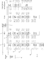
Jede einzelne Blasstation weist eine Antriebseinrichtung 16 für eine (nicht gezeigte) Reckstange sowie eine Vielzahl von Ventilen 12 auf, welche den eigentlichen Blasvorgang steuern. Auch die elektrische Versorgung dieser Antriebseinrichtungen kann über den Schleifring 6 erfolgen.Each individual blowing station has a
Daneben weist jede Blasstation eine und bevorzugt mehrere Sensoreinrichtungen 22 auf, welche ebenfalls in Kommunikationsverbindung mit der jeweiligen Steuereinrichtung 20 stehen. Weiterhin weist jede Blasstation bzw. deren Steuerungseinrichtung 20 einen Zeitgeber 24 auf, der in Abhängigkeit von einem Startsignal den betreffenden Blasvorgang steuert. Das Bezugszeichen 30 bezieht sich auf einen Positionssensor, der eine Winkelposition des Blasrads erfasst. Diese Winkelinformation wird einer zentralen Steuereinrichtung 40, die stehend vorgesehen ist, über eine Kommunikationsverbindung 32 weitergeleitet.In addition, each blow station has one and preferably a plurality of
Über eine Kommunikationsverbindung 13 wird über den Schleifring 6 eine entsprechende Zeitinformation sowie ein Starttriggersignal an die Steuereinrichtungen 20 weitergegeben. Weiterhin wird in Abhängigkeit von der von dem Positionssensor 30 ermittelten Position des Blasrads festgestellt, welche der einzelnen Blasstationen 4 gerade einen Vorformling übernommen hat. An diese entsprechende Blasstation wird ein Startsignal gesendet und in Abhängigkeit von diesem Startsignal wird der Expansionsvorgang der Behältnisse eingeleitet. Das Bezugszeichen 18 bezieht sich auf eine Speichereinrichtung. Jede der einzelnen Steuereinrichtungen weist hier eine Speichereinrichtung 18 auf. In dieser Speichereinrichtung können beispielsweise Daten abgelegt sein, welche den zeitlichen Ablauf der Ventilsteuerung oder auch der Reckstangenbewegung regeln. Daneben können auch Sollwerte abgelegt sein, die mit von den Sensoreinrichtungen 22 ausgegebenen Messwerten verglichen werden können. Die Steuereinrichtungen 20 kommunizieren jeweils über Verbindungsleitungen 21 mit den Blasstationen
Das Bezugszeichen 17 bezieht sich auf eine Zuleitung, welche ein gasförmiges Medium an die Ventile 12 leitet. Weitere entsprechende Zuleitungen sind nicht dargestellt.The
Auch könnten weitere spezielle Kundenwünsche in die Ansteuerung durch die Steuereinrichtung integriert werden. Das Bezugszeichen 46 bezieht sich auf Sensoreinrichtungen hier in Form von sogenannten PT100, welche eine Temperatur der entsprechenden Blasform bestimmen. In Kenntnis dieser Temperatur ist eine noch genauere Steuerung des Blasvorgangs möglich wobei die Berücksichtigung dieser Formtemperatur jedoch optional ist. Wie oben erwähnt wird auch die Steuerung der Reckkurve direkt von der Steuerungseinrichtung 20 übernommen. Diese Ansteuerung ist aus Gründen der Vereinfachung nur bei einer Blasstation eingezeichnet, tatsächlich jedoch bei allen Stationen vorhanden.Also, other special customer requests could be integrated into the control by the control device. The
Nachdem alle Ventile abgearbeitet sind, erfolgt die Abarbeitung für die jeweils nächste Blasstation. Diese Vorgänge werden jeweils noch in der zentralen Steuerungseinrichtung 40 vorgenommen. Auf diese Weise werden für den bestimmten Drehwinkel des Blasrads die Zustände aller Ventile bestimmt und diese werden anschließend an die einzelnen Steuerungseinrichtungen 20 weitergeleitet. Auf diese Weise wird in der zentralen Steuerungseinrichtung ein Vergleich zwischen den betreffenden Start- und Endwinkeln und dem gemessenen Winkel des Blasrads vorgenommen und die Ergebnisse dieses Vergleichs werden in den einzelnen Steuerungseinrichtungen umgesetzt.After all valves have been processed, processing is carried out for the next blowing station. These processes are still carried out in the
Die einzelnen Startzeiten und Endzeiten für die ermittelte Blasform werden in die vorgesehene Steuerungseinrichtung 20 eingelesen. Weiterhin wird in Beantwortung auf das Triggersignal der Zeitgeber gestartet. Danach wird für jedes Ventil die eingelesene Start- und die eingelesene Endzeit mit der Zeit des Zeitgebers verglichen, und so lange die Zeit des Zeitgebers zwischen der Startzeit und der Endzeit liegt, wird das entsprechende Ventil geöffnet. Dieser Vorgang wird für alle Ventile hintereinander durchgeführt. Damit erfolgen im Falle des in
Damit kann der Ablauf der Behälterexpansion zeitbasiert gesteuert werden und damit auch unabhängig von der Transportgeschwindigkeit des Blasrads gehalten werden.Thus, the flow of container expansion can be controlled time-based and thus kept independent of the transport speed of the blowing wheel.
Vorzugsweise werden die Winkelpositionen in regelmäßigen Zeitabständen eingelesen und in Abhängigkeit hiervon jeweils die gerade zu bestückende Blasstation bestimmt.Preferably, the angular positions are read in at regular intervals and, in each case, the blow station to be fitted in each case is determined in dependence thereon.
Bei einer weiteren Ausführungsform wäre es auch möglich, die Peripherie in ausgelagerten Ein- und Ausgabebaugruppen vorzusehen, die über lokale Bussysteme oder Multipolstecker an die Steuereinrichtungen bzw. Servoumrichter 20 angebunden werden. Auf diese Weise ist es möglich, die Peripherie dort zu montieren, wo auch die Aktorik und die Sensorik platziert ist, was zu einer übersichtlichen Verdrahtung führt. Es wäre jedoch auch denkbar, die Aktorik und Sensorik in sogenannten Inseln oder Blöcken zusammen zu fassen und durch Integration von elektronischen Bauteilen busfähig auszuführen. Auf diese Weise lassen sich die dezentralen Periferiemodule einsparen. Beispielsweise sind von vielen Pneumatikherstellern Ventilinseln erhältlich, bei denen die einzelnen Ventile zu Gruppen zusammengefasst und mit einem Bus- Ansteuermodul versehen sind.In a further embodiment, it would also be possible to provide the peripherals in outsourced input and output modules which are connected via local bus systems or multipole connectors to the control devices or servo-
Bevorzugt arbeiten damit die einzelnen Steuerungseinrichtungen 20 autark, jedoch bei der in
Zusätzlich ist bei den in den
Bei dem in
Bei einer bevorzugten Ausführungsform ist es möglich, die Steuerungseinrichtung direkt an der Antriebseinrichtung anzuordnen. So ist es möglich, als Antrieb für die Reckstange einen sogenannten Frequenzumrichtermotor vorzusehen. Diese Frequenzumrichtung bzw. deren Steuerung kann auch die Ansteuerung der Ventile übernehmen.In a preferred embodiment, it is possible, the control device directly to the drive device to arrange. Thus, it is possible to provide a drive for the stretch rod a so-called frequency converter motor. This frequency conversion or its control can also take over the control of the valves.
Claims (12)
- Apparatus (1) for producing plastic containers, comprising a transport device (2), on which there is arranged a plurality of blowing stations (4) for expanding preforms to form plastic containers, wherein each of these blowing stations has a receiving space for a preform to be expanded, at least one supply line for supplying a gaseous medium to the preform, at least one valve (12) which controls the supply of the gaseous medium to the preform, a mechanically operated stretching element (14) for stretching the preforms, and each blowing station (4) has an independent control device (20),
characterised in that each station has an own electrical drive device (16) for moving the stretching element (14), and wherein each control device (20) controls both the valve (12) and the drive device (16) for moving the stretching element (14) for producing the plastic container time based depending on a starting signal, wherein each blowing station (4) has a timer (24) which can be activated depending on the starting signal and controls a time frame for a blowing process and processes which take place during the blowing process, wherein the timer (24) is designed in such a way that an angle information is read in by the timer, to preset processes that take place accurately timed by means of these angle information specifically for each blowing station (4), wherein the timer (24) is started at a specific angle and after that an angle independent process control takes place. - Apparatus (1) according to claim 1, characterised in that each blowing station (4) has a plurality of valves (12) which control the supply of gaseous media to the containers.
- Apparatus according to at least one of the preceding claims, characterised in that the mechanically operated stretching element (14) is a stretching rod (14).
- Apparatus according to at least one of the preceding claims, characterised in that at least one blowing station has a sensor device (22) which senses a physical state of the container (10) or of the blowing station.
- Apparatus according to claim 4, characterised in that the sensor device (22) is in communication connection with the control device (20).
- Apparatus according to at least one of the preceding claims, characterised in that the apparatus has a position sensor (30) which senses a position of the transport device (2).
- Apparatus according to at least one of the preceding claims, characterised in that the apparatus has a central control device (40) which is in communication connection with the control devices (20) of the individual blowing stations (4).
- Apparatus according to at least one of the preceding claims, characterised in that the apparatus has a memory device (18), in which correlation data for controlling the drive device (14) and the valves (12) are stored.
- Method for producing plastic containers from preforms, wherein the preforms are transported in a plurality of blowing stations (4), wherein the blowing stations are transported with a transport device (2) and during this transport are expanded to form plastic containers, wherein, for the expansion process, a gaseous medium is supplied to the preforms in each blowing station (4) and the supply of this gaseous medium is controlled by means of at least one valve (12), and wherein the containers (10) are stretched by at least one mechanically operated stretching element (14) in each blowing station (4) for the expansion process, and each blowing station (4) has an independent controlling device (20), characterised in that each of those stretching elements (14) can move independently of each of the other stretching elements (14) by means of a respective own electronic drive device (16), and wherein each control device (20) controls both the stretching process and the supply of the gaseous medium into the containers time based depending on a starting signal, which can be transmitted to a selected blowing statin (4), wherein a timer (24) of this blowing station (4) is activated depending on the starting signal and controls a time frame for a blowing process and processes which take place during the blowing process, and wherein the timer (24) is designed in such a way that an angle information is read in by the timer, to preset processes that take place accurately timed by means of these angle information specifically for each blowing station (4), wherein the timer (24) is started at a specific angle and after that an angle independent process control takes place.
- Method according to claim 9, characterised in that positions of the transport device (2) are sensed by means of a position sensor (30).
- Method according to claim 10, characterised in that a certain blowing station (4) is selected in reaction to a sensing of the position of the transport device (2).
- Method according to at least one of the preceding claims 9 to 11, characterised in that the control of the drive elements (16) and of the valve (12) are correlated with one another.
Applications Claiming Priority (1)
| Application Number | Priority Date | Filing Date | Title |
|---|---|---|---|
| DE102008012757A DE102008012757A1 (en) | 2008-03-05 | 2008-03-05 | Device for producing plastic containers |
Publications (3)
| Publication Number | Publication Date |
|---|---|
| EP2098356A2 EP2098356A2 (en) | 2009-09-09 |
| EP2098356A3 EP2098356A3 (en) | 2012-05-30 |
| EP2098356B1 true EP2098356B1 (en) | 2017-01-18 |
Family
ID=40677694
Family Applications (1)
| Application Number | Title | Priority Date | Filing Date |
|---|---|---|---|
| EP09153845.4A Active EP2098356B1 (en) | 2008-03-05 | 2009-02-27 | Device and method for producing plastic containers |
Country Status (3)
| Country | Link |
|---|---|
| EP (1) | EP2098356B1 (en) |
| CN (1) | CN101559648B (en) |
| DE (1) | DE102008012757A1 (en) |
Cited By (2)
| Publication number | Priority date | Publication date | Assignee | Title |
|---|---|---|---|---|
| EP3898174B1 (en) | 2018-12-19 | 2023-01-25 | Sidel Participations | Production line for producing containers controlled by a position determining device |
| EP3964348B1 (en) | 2020-09-04 | 2023-07-26 | Krones AG | Method and device for heating plastic pre-forms with spatially resolved temperature detection |
Families Citing this family (19)
| Publication number | Priority date | Publication date | Assignee | Title |
|---|---|---|---|---|
| DE102009044258A1 (en) | 2009-10-15 | 2011-05-05 | Krones Ag | Plant and process for the production, filling, packaging and / or transport of beverages |
| DE102009058086A1 (en) | 2009-12-14 | 2011-06-16 | Krones Ag | Apparatus and method for treating containers with clothing detection |
| DE102010003350A1 (en) † | 2010-03-26 | 2011-09-29 | Krones Ag | Method for producing plastic containers |
| DE102010028255A1 (en) | 2010-04-27 | 2011-10-27 | Krones Ag | stretch |
| DE102010028253A1 (en) | 2010-04-27 | 2011-10-27 | Krones Ag | blow molding machine |
| DE102010047104A1 (en) * | 2010-10-01 | 2012-04-05 | Krones Aktiengesellschaft | Device for forming plastic preforms into plastic containers with variable output |
| FR2993198B1 (en) | 2012-07-13 | 2015-02-20 | Sidel Participations | CONTROL SYSTEM FOR A CONTAINER FORMING UNIT COMPRISING A MASTER CONTROL UNIT AND SLAVE CONTROLLERS |
| DE102012212773A1 (en) | 2012-07-20 | 2014-01-23 | Krones Ag | BLOWING MACHINE WITH INSIDE TEMPERING UNIT |
| DE102012106916A1 (en) * | 2012-07-30 | 2014-05-22 | Krones Ag | Apparatus and method for forming plastic preforms with separate flow paths for blowing air and control air |
| DE102012024420A1 (en) | 2012-12-14 | 2014-07-03 | Krones Ag | Optimized preform feeder |
| DE102012112370A1 (en) * | 2012-12-17 | 2014-06-18 | Krones Ag | Device for heating plastic preforms |
| FR3024071B1 (en) * | 2014-07-25 | 2016-08-19 | Sidel Participations | METHOD FOR CONTROLLING A PROCESS FOR BLOWING PLASTIC CONTAINERS |
| FR3053621B1 (en) | 2016-07-11 | 2018-08-03 | Sidel Participations | PROCESS FOR MANUFACTURING PLASTIC CONTAINERS BY BLOWING |
| DE102017215443A1 (en) * | 2017-09-04 | 2019-03-07 | Krones Ag | Rotary machine for handling containers |
| CN109483854A (en) * | 2018-12-31 | 2019-03-19 | 宁波新博来万机械有限公司 | A kind of novel hot tank bottle blowing machine |
| EP3941711B1 (en) * | 2019-03-22 | 2023-04-26 | Eugen Seitz AG | Blow valve device of a blowing device |
| FR3105754A1 (en) * | 2019-12-30 | 2021-07-02 | Sidel Participations | Method for determining a theoretical angular position of a transport wheel for the production of containers |
| DE102020131266A1 (en) * | 2020-11-25 | 2022-05-25 | Krones Aktiengesellschaft | Position monitoring of a curve element in a container treatment plant |
| CN114734614A (en) * | 2022-05-11 | 2022-07-12 | 广州达意隆包装机械股份有限公司 | Bottle blowing machine control system and bottle blowing machine |
Family Cites Families (4)
| Publication number | Priority date | Publication date | Assignee | Title |
|---|---|---|---|---|
| DE10153045A1 (en) | 2001-10-26 | 2003-05-08 | Sig Corpoplast Gmbh & Co Kg | Method and device for controlling a blowing process |
| DE102004044260A1 (en) * | 2004-09-14 | 2006-04-06 | Sig Technology Ltd. | Method and apparatus for blow molding containers |
| DE102007005489A1 (en) * | 2007-01-30 | 2007-07-26 | Bachmann Gmbh | Rotary blow-molding machine, includes drum cylinder surrounded by workstations with autonomous controllers inputting data from angular encoder via field bus |
| DE102007005498A1 (en) | 2007-01-30 | 2008-07-31 | Behr Gmbh & Co. Kg | Air conditioner, particularly vehicle air conditioner, has coolant cycle, in which compressor, gas cooler and air flow through compressor are arranged, and regulating device is provided for performance of compressor |
-
2008
- 2008-03-05 DE DE102008012757A patent/DE102008012757A1/en active Pending
-
2009
- 2009-02-27 EP EP09153845.4A patent/EP2098356B1/en active Active
- 2009-03-03 CN CN200910127405.0A patent/CN101559648B/en active Active
Non-Patent Citations (1)
| Title |
|---|
| None * |
Cited By (2)
| Publication number | Priority date | Publication date | Assignee | Title |
|---|---|---|---|---|
| EP3898174B1 (en) | 2018-12-19 | 2023-01-25 | Sidel Participations | Production line for producing containers controlled by a position determining device |
| EP3964348B1 (en) | 2020-09-04 | 2023-07-26 | Krones AG | Method and device for heating plastic pre-forms with spatially resolved temperature detection |
Also Published As
| Publication number | Publication date |
|---|---|
| CN101559648A (en) | 2009-10-21 |
| EP2098356A2 (en) | 2009-09-09 |
| EP2098356A3 (en) | 2012-05-30 |
| DE102008012757A1 (en) | 2009-09-10 |
| CN101559648B (en) | 2015-06-17 |
Similar Documents
| Publication | Publication Date | Title |
|---|---|---|
| EP2098356B1 (en) | Device and method for producing plastic containers | |
| EP1306195B1 (en) | Process and apparatus for controlling a blow operation | |
| EP2263854B1 (en) | Electrically operated blow-moulding machine and the method | |
| EP2436507B1 (en) | Device and method for reforming plastic preforms into plastic containers with variable output performance | |
| EP3129206B1 (en) | Device and method for transporting and handling containers | |
| EP2743057B1 (en) | Device for heating plastic pre-forms | |
| EP2477937A2 (en) | Device for producing containers for liquid | |
| DE10116665B4 (en) | Method for controlling a blowing process in the manufacture of containers made of a thermoplastic material | |
| EP3294523B1 (en) | Changing blow moulds in blow moulding machines | |
| DE202013009941U1 (en) | Apparatus for blow-molding containers with a drive device and coupled motion sequences | |
| DE102015116073A1 (en) | Method and device for carrying out switching operations in devices for producing beverage containers | |
| DE19737697B4 (en) | injection blow molding machine | |
| EP3157753B1 (en) | Intermittently operating printing machine | |
| EP1566258B1 (en) | Apparatus for machining workpieces | |
| DE19847908C1 (en) | Process for regulating drive unit of injection molding machine comprises reporting deviations from desired values to a centralized control unit | |
| EP4067049B1 (en) | Device for reforming plastic preforms into plastic containers with decoupled drives | |
| EP3384351B1 (en) | Method for transporting containers | |
| EP3793803B1 (en) | Method and device for shaping plastic pre-forms to form plastic containers involving the prior bringing to temperaturepreliminary temperature control of blow moulds | |
| EP3580035B1 (en) | Device and method for transforming plastic preforms into plastic bottles with a moveable base | |
| DE2535367C3 (en) | Device for the production of hollow objects by the blow molding process | |
| EP3103617B1 (en) | Device and method for manufacturing oval plastic containers | |
| EP3103618B1 (en) | Device and method for manufacturing oval plastic containers | |
| DE10165127B3 (en) | Method for controlling a blowing process in the manufacture of containers made of a thermoplastic material | |
| DE2535367B2 (en) | DEVICE FOR THE PRODUCTION OF HOLLOW OBJECTS BY THE BLOW METHOD | |
| DE19919038C2 (en) | Process for heating a stretching aid |
Legal Events
| Date | Code | Title | Description |
|---|---|---|---|
| PUAI | Public reference made under article 153(3) epc to a published international application that has entered the european phase |
Free format text: ORIGINAL CODE: 0009012 |
|
| AK | Designated contracting states |
Kind code of ref document: A2 Designated state(s): AT BE BG CH CY CZ DE DK EE ES FI FR GB GR HR HU IE IS IT LI LT LU LV MC MK MT NL NO PL PT RO SE SI SK TR |
|
| AX | Request for extension of the european patent |
Extension state: AL BA RS |
|
| PUAL | Search report despatched |
Free format text: ORIGINAL CODE: 0009013 |
|
| AK | Designated contracting states |
Kind code of ref document: A3 Designated state(s): AT BE BG CH CY CZ DE DK EE ES FI FR GB GR HR HU IE IS IT LI LT LU LV MC MK MT NL NO PL PT RO SE SI SK TR |
|
| AX | Request for extension of the european patent |
Extension state: AL BA RS |
|
| RIC1 | Information provided on ipc code assigned before grant |
Ipc: B29C 49/42 20060101ALN20120424BHEP Ipc: B29C 49/06 20060101ALN20120424BHEP Ipc: B29C 49/48 20060101ALN20120424BHEP Ipc: B29C 49/12 20060101ALI20120424BHEP Ipc: B29C 49/36 20060101ALN20120424BHEP Ipc: B29C 49/78 20060101AFI20120424BHEP Ipc: B29C 49/58 20060101ALI20120424BHEP Ipc: B29K 67/00 20060101ALI20120424BHEP |
|
| 17P | Request for examination filed |
Effective date: 20121129 |
|
| AKX | Designation fees paid |
Designated state(s): AT BE BG CH CY CZ DE DK EE ES FI FR GB GR HR HU IE IS IT LI LT LU LV MC MK MT NL NO PL PT RO SE SI SK TR |
|
| 17Q | First examination report despatched |
Effective date: 20150605 |
|
| GRAP | Despatch of communication of intention to grant a patent |
Free format text: ORIGINAL CODE: EPIDOSNIGR1 |
|
| RIC1 | Information provided on ipc code assigned before grant |
Ipc: B29C 49/36 20060101ALN20160219BHEP Ipc: B29C 49/12 20060101ALI20160219BHEP Ipc: B29C 49/48 20060101ALN20160219BHEP Ipc: B29C 49/06 20060101ALN20160219BHEP Ipc: B29C 49/58 20060101ALI20160219BHEP Ipc: B29K 67/00 20060101ALI20160219BHEP Ipc: B29C 49/78 20060101AFI20160219BHEP Ipc: B29C 49/42 20060101ALN20160219BHEP Ipc: B29C 33/26 20060101ALN20160219BHEP |
|
| RIC1 | Information provided on ipc code assigned before grant |
Ipc: B29C 33/26 20060101ALN20160303BHEP Ipc: B29C 49/42 20060101ALN20160303BHEP Ipc: B29K 67/00 20060101ALI20160303BHEP Ipc: B29C 49/36 20060101ALN20160303BHEP Ipc: B29C 49/12 20060101ALI20160303BHEP Ipc: B29C 49/78 20060101AFI20160303BHEP Ipc: B29C 49/58 20060101ALI20160303BHEP Ipc: B29C 49/48 20060101ALN20160303BHEP Ipc: B29C 49/06 20060101ALN20160303BHEP |
|
| INTG | Intention to grant announced |
Effective date: 20160315 |
|
| RIC1 | Information provided on ipc code assigned before grant |
Ipc: B29C 49/58 20060101ALI20160307BHEP Ipc: B29C 49/06 20060101ALN20160307BHEP Ipc: B29K 67/00 20060101ALI20160307BHEP Ipc: B29C 49/42 20060101ALN20160307BHEP Ipc: B29C 49/78 20060101AFI20160307BHEP Ipc: B29C 33/26 20060101ALN20160307BHEP Ipc: B29C 49/36 20060101ALN20160307BHEP Ipc: B29C 49/12 20060101ALI20160307BHEP Ipc: B29C 49/48 20060101ALN20160307BHEP |
|
| GRAJ | Information related to disapproval of communication of intention to grant by the applicant or resumption of examination proceedings by the epo deleted |
Free format text: ORIGINAL CODE: EPIDOSDIGR1 |
|
| INTC | Intention to grant announced (deleted) | ||
| RIC1 | Information provided on ipc code assigned before grant |
Ipc: B29C 49/42 20060101ALN20160713BHEP Ipc: B29K 67/00 20060101ALI20160713BHEP Ipc: B29C 49/36 20060101ALN20160713BHEP Ipc: B29C 49/06 20060101ALN20160713BHEP Ipc: B29C 49/12 20060101ALI20160713BHEP Ipc: B29C 33/26 20060101ALN20160713BHEP Ipc: B29C 49/58 20060101ALI20160713BHEP Ipc: B29C 49/78 20060101AFI20160713BHEP Ipc: B29C 49/48 20060101ALN20160713BHEP |
|
| GRAP | Despatch of communication of intention to grant a patent |
Free format text: ORIGINAL CODE: EPIDOSNIGR1 |
|
| INTG | Intention to grant announced |
Effective date: 20160822 |
|
| GRAS | Grant fee paid |
Free format text: ORIGINAL CODE: EPIDOSNIGR3 |
|
| GRAA | (expected) grant |
Free format text: ORIGINAL CODE: 0009210 |
|
| AK | Designated contracting states |
Kind code of ref document: B1 Designated state(s): AT BE BG CH CY CZ DE DK EE ES FI FR GB GR HR HU IE IS IT LI LT LU LV MC MK MT NL NO PL PT RO SE SI SK TR |
|
| REG | Reference to a national code |
Ref country code: GB Ref legal event code: FG4D Free format text: NOT ENGLISH |
|
| REG | Reference to a national code |
Ref country code: FR Ref legal event code: PLFP Year of fee payment: 9 |
|
| REG | Reference to a national code |
Ref country code: CH Ref legal event code: EP |
|
| REG | Reference to a national code |
Ref country code: AT Ref legal event code: REF Ref document number: 862649 Country of ref document: AT Kind code of ref document: T Effective date: 20170215 |
|
| REG | Reference to a national code |
Ref country code: IE Ref legal event code: FG4D Free format text: LANGUAGE OF EP DOCUMENT: GERMAN |
|
| REG | Reference to a national code |
Ref country code: DE Ref legal event code: R096 Ref document number: 502009013576 Country of ref document: DE |
|
| REG | Reference to a national code |
Ref country code: NL Ref legal event code: MP Effective date: 20170118 |
|
| REG | Reference to a national code |
Ref country code: LT Ref legal event code: MG4D |
|
| PG25 | Lapsed in a contracting state [announced via postgrant information from national office to epo] |
Ref country code: BE Free format text: LAPSE BECAUSE OF NON-PAYMENT OF DUE FEES Effective date: 20170228 |
|
| PG25 | Lapsed in a contracting state [announced via postgrant information from national office to epo] |
Ref country code: NL Free format text: LAPSE BECAUSE OF FAILURE TO SUBMIT A TRANSLATION OF THE DESCRIPTION OR TO PAY THE FEE WITHIN THE PRESCRIBED TIME-LIMIT Effective date: 20170118 |
|
| PG25 | Lapsed in a contracting state [announced via postgrant information from national office to epo] |
Ref country code: HR Free format text: LAPSE BECAUSE OF FAILURE TO SUBMIT A TRANSLATION OF THE DESCRIPTION OR TO PAY THE FEE WITHIN THE PRESCRIBED TIME-LIMIT Effective date: 20170118 Ref country code: IS Free format text: LAPSE BECAUSE OF FAILURE TO SUBMIT A TRANSLATION OF THE DESCRIPTION OR TO PAY THE FEE WITHIN THE PRESCRIBED TIME-LIMIT Effective date: 20170518 Ref country code: FI Free format text: LAPSE BECAUSE OF FAILURE TO SUBMIT A TRANSLATION OF THE DESCRIPTION OR TO PAY THE FEE WITHIN THE PRESCRIBED TIME-LIMIT Effective date: 20170118 Ref country code: NO Free format text: LAPSE BECAUSE OF FAILURE TO SUBMIT A TRANSLATION OF THE DESCRIPTION OR TO PAY THE FEE WITHIN THE PRESCRIBED TIME-LIMIT Effective date: 20170418 Ref country code: GR Free format text: LAPSE BECAUSE OF FAILURE TO SUBMIT A TRANSLATION OF THE DESCRIPTION OR TO PAY THE FEE WITHIN THE PRESCRIBED TIME-LIMIT Effective date: 20170419 Ref country code: LT Free format text: LAPSE BECAUSE OF FAILURE TO SUBMIT A TRANSLATION OF THE DESCRIPTION OR TO PAY THE FEE WITHIN THE PRESCRIBED TIME-LIMIT Effective date: 20170118 |
|
| PG25 | Lapsed in a contracting state [announced via postgrant information from national office to epo] |
Ref country code: ES Free format text: LAPSE BECAUSE OF FAILURE TO SUBMIT A TRANSLATION OF THE DESCRIPTION OR TO PAY THE FEE WITHIN THE PRESCRIBED TIME-LIMIT Effective date: 20170118 Ref country code: PL Free format text: LAPSE BECAUSE OF FAILURE TO SUBMIT A TRANSLATION OF THE DESCRIPTION OR TO PAY THE FEE WITHIN THE PRESCRIBED TIME-LIMIT Effective date: 20170118 Ref country code: SE Free format text: LAPSE BECAUSE OF FAILURE TO SUBMIT A TRANSLATION OF THE DESCRIPTION OR TO PAY THE FEE WITHIN THE PRESCRIBED TIME-LIMIT Effective date: 20170118 Ref country code: PT Free format text: LAPSE BECAUSE OF FAILURE TO SUBMIT A TRANSLATION OF THE DESCRIPTION OR TO PAY THE FEE WITHIN THE PRESCRIBED TIME-LIMIT Effective date: 20170518 Ref country code: BG Free format text: LAPSE BECAUSE OF FAILURE TO SUBMIT A TRANSLATION OF THE DESCRIPTION OR TO PAY THE FEE WITHIN THE PRESCRIBED TIME-LIMIT Effective date: 20170418 Ref country code: LV Free format text: LAPSE BECAUSE OF FAILURE TO SUBMIT A TRANSLATION OF THE DESCRIPTION OR TO PAY THE FEE WITHIN THE PRESCRIBED TIME-LIMIT Effective date: 20170118 |
|
| REG | Reference to a national code |
Ref country code: CH Ref legal event code: PL |
|
| REG | Reference to a national code |
Ref country code: DE Ref legal event code: R097 Ref document number: 502009013576 Country of ref document: DE |
|
| PG25 | Lapsed in a contracting state [announced via postgrant information from national office to epo] |
Ref country code: SK Free format text: LAPSE BECAUSE OF FAILURE TO SUBMIT A TRANSLATION OF THE DESCRIPTION OR TO PAY THE FEE WITHIN THE PRESCRIBED TIME-LIMIT Effective date: 20170118 Ref country code: CZ Free format text: LAPSE BECAUSE OF FAILURE TO SUBMIT A TRANSLATION OF THE DESCRIPTION OR TO PAY THE FEE WITHIN THE PRESCRIBED TIME-LIMIT Effective date: 20170118 Ref country code: RO Free format text: LAPSE BECAUSE OF FAILURE TO SUBMIT A TRANSLATION OF THE DESCRIPTION OR TO PAY THE FEE WITHIN THE PRESCRIBED TIME-LIMIT Effective date: 20170118 Ref country code: EE Free format text: LAPSE BECAUSE OF FAILURE TO SUBMIT A TRANSLATION OF THE DESCRIPTION OR TO PAY THE FEE WITHIN THE PRESCRIBED TIME-LIMIT Effective date: 20170118 Ref country code: CH Free format text: LAPSE BECAUSE OF NON-PAYMENT OF DUE FEES Effective date: 20170228 Ref country code: LI Free format text: LAPSE BECAUSE OF NON-PAYMENT OF DUE FEES Effective date: 20170228 |
|
| PLBE | No opposition filed within time limit |
Free format text: ORIGINAL CODE: 0009261 |
|
| STAA | Information on the status of an ep patent application or granted ep patent |
Free format text: STATUS: NO OPPOSITION FILED WITHIN TIME LIMIT |
|
| REG | Reference to a national code |
Ref country code: IE Ref legal event code: MM4A |
|
| PG25 | Lapsed in a contracting state [announced via postgrant information from national office to epo] |
Ref country code: MC Free format text: LAPSE BECAUSE OF FAILURE TO SUBMIT A TRANSLATION OF THE DESCRIPTION OR TO PAY THE FEE WITHIN THE PRESCRIBED TIME-LIMIT Effective date: 20170118 Ref country code: DK Free format text: LAPSE BECAUSE OF FAILURE TO SUBMIT A TRANSLATION OF THE DESCRIPTION OR TO PAY THE FEE WITHIN THE PRESCRIBED TIME-LIMIT Effective date: 20170118 |
|
| 26N | No opposition filed |
Effective date: 20171019 |
|
| GBPC | Gb: european patent ceased through non-payment of renewal fee |
Effective date: 20170418 |
|
| PG25 | Lapsed in a contracting state [announced via postgrant information from national office to epo] |
Ref country code: LU Free format text: LAPSE BECAUSE OF NON-PAYMENT OF DUE FEES Effective date: 20170227 |
|
| REG | Reference to a national code |
Ref country code: FR Ref legal event code: PLFP Year of fee payment: 10 |
|
| REG | Reference to a national code |
Ref country code: BE Ref legal event code: MM Effective date: 20170228 |
|
| PG25 | Lapsed in a contracting state [announced via postgrant information from national office to epo] |
Ref country code: GB Free format text: LAPSE BECAUSE OF NON-PAYMENT OF DUE FEES Effective date: 20170418 Ref country code: SI Free format text: LAPSE BECAUSE OF FAILURE TO SUBMIT A TRANSLATION OF THE DESCRIPTION OR TO PAY THE FEE WITHIN THE PRESCRIBED TIME-LIMIT Effective date: 20170118 Ref country code: IE Free format text: LAPSE BECAUSE OF NON-PAYMENT OF DUE FEES Effective date: 20170227 |
|
| REG | Reference to a national code |
Ref country code: AT Ref legal event code: MM01 Ref document number: 862649 Country of ref document: AT Kind code of ref document: T Effective date: 20170227 |
|
| PG25 | Lapsed in a contracting state [announced via postgrant information from national office to epo] |
Ref country code: AT Free format text: LAPSE BECAUSE OF NON-PAYMENT OF DUE FEES Effective date: 20170227 |
|
| PG25 | Lapsed in a contracting state [announced via postgrant information from national office to epo] |
Ref country code: MT Free format text: LAPSE BECAUSE OF FAILURE TO SUBMIT A TRANSLATION OF THE DESCRIPTION OR TO PAY THE FEE WITHIN THE PRESCRIBED TIME-LIMIT Effective date: 20170118 |
|
| PG25 | Lapsed in a contracting state [announced via postgrant information from national office to epo] |
Ref country code: HU Free format text: LAPSE BECAUSE OF FAILURE TO SUBMIT A TRANSLATION OF THE DESCRIPTION OR TO PAY THE FEE WITHIN THE PRESCRIBED TIME-LIMIT; INVALID AB INITIO Effective date: 20090227 |
|
| PG25 | Lapsed in a contracting state [announced via postgrant information from national office to epo] |
Ref country code: CY Free format text: LAPSE BECAUSE OF NON-PAYMENT OF DUE FEES Effective date: 20170118 |
|
| PG25 | Lapsed in a contracting state [announced via postgrant information from national office to epo] |
Ref country code: MK Free format text: LAPSE BECAUSE OF FAILURE TO SUBMIT A TRANSLATION OF THE DESCRIPTION OR TO PAY THE FEE WITHIN THE PRESCRIBED TIME-LIMIT Effective date: 20170118 |
|
| PG25 | Lapsed in a contracting state [announced via postgrant information from national office to epo] |
Ref country code: TR Free format text: LAPSE BECAUSE OF FAILURE TO SUBMIT A TRANSLATION OF THE DESCRIPTION OR TO PAY THE FEE WITHIN THE PRESCRIBED TIME-LIMIT Effective date: 20170118 |
|
| PGFP | Annual fee paid to national office [announced via postgrant information from national office to epo] |
Ref country code: IT Payment date: 20230110 Year of fee payment: 15 Ref country code: DE Payment date: 20221230 Year of fee payment: 15 |
|
| P01 | Opt-out of the competence of the unified patent court (upc) registered |
Effective date: 20230523 |
|
| PGFP | Annual fee paid to national office [announced via postgrant information from national office to epo] |
Ref country code: FR Payment date: 20231229 Year of fee payment: 16 |