EP1998950B1 - PROCEDE ET DISPOSITIF DE FORMAge-SOUFFLAGE DE RECIPIENTS PAR RECOURS A LA MESURE DE L'EPAISSEUR DE PAROIS DE L'OBJET FACONNE - Google Patents
PROCEDE ET DISPOSITIF DE FORMAge-SOUFFLAGE DE RECIPIENTS PAR RECOURS A LA MESURE DE L'EPAISSEUR DE PAROIS DE L'OBJET FACONNE Download PDFInfo
- Publication number
- EP1998950B1 EP1998950B1 EP07721945.9A EP07721945A EP1998950B1 EP 1998950 B1 EP1998950 B1 EP 1998950B1 EP 07721945 A EP07721945 A EP 07721945A EP 1998950 B1 EP1998950 B1 EP 1998950B1
- Authority
- EP
- European Patent Office
- Prior art keywords
- wall thickness
- regulation
- preforms
- container
- temperature
- Prior art date
- Legal status (The legal status is an assumption and is not a legal conclusion. Google has not performed a legal analysis and makes no representation as to the accuracy of the status listed.)
- Not-in-force
Links
Images


Classifications
-
- B—PERFORMING OPERATIONS; TRANSPORTING
- B29—WORKING OF PLASTICS; WORKING OF SUBSTANCES IN A PLASTIC STATE IN GENERAL
- B29C—SHAPING OR JOINING OF PLASTICS; SHAPING OF MATERIAL IN A PLASTIC STATE, NOT OTHERWISE PROVIDED FOR; AFTER-TREATMENT OF THE SHAPED PRODUCTS, e.g. REPAIRING
- B29C49/00—Blow-moulding, i.e. blowing a preform or parison to a desired shape within a mould; Apparatus therefor
- B29C49/42—Component parts, details or accessories; Auxiliary operations
- B29C49/78—Measuring, controlling or regulating
-
- B—PERFORMING OPERATIONS; TRANSPORTING
- B29—WORKING OF PLASTICS; WORKING OF SUBSTANCES IN A PLASTIC STATE IN GENERAL
- B29C—SHAPING OR JOINING OF PLASTICS; SHAPING OF MATERIAL IN A PLASTIC STATE, NOT OTHERWISE PROVIDED FOR; AFTER-TREATMENT OF THE SHAPED PRODUCTS, e.g. REPAIRING
- B29C49/00—Blow-moulding, i.e. blowing a preform or parison to a desired shape within a mould; Apparatus therefor
- B29C49/42—Component parts, details or accessories; Auxiliary operations
- B29C49/48—Moulds
- B29C2049/4879—Moulds characterised by mould configurations
- B29C2049/4889—Mould halves consisting of an independent neck, main and bottom part
-
- B—PERFORMING OPERATIONS; TRANSPORTING
- B29—WORKING OF PLASTICS; WORKING OF SUBSTANCES IN A PLASTIC STATE IN GENERAL
- B29C—SHAPING OR JOINING OF PLASTICS; SHAPING OF MATERIAL IN A PLASTIC STATE, NOT OTHERWISE PROVIDED FOR; AFTER-TREATMENT OF THE SHAPED PRODUCTS, e.g. REPAIRING
- B29C49/00—Blow-moulding, i.e. blowing a preform or parison to a desired shape within a mould; Apparatus therefor
- B29C49/42—Component parts, details or accessories; Auxiliary operations
- B29C49/78—Measuring, controlling or regulating
- B29C49/783—Measuring, controlling or regulating blowing pressure
- B29C2049/7831—Measuring, controlling or regulating blowing pressure characterised by pressure values or ranges
-
- B—PERFORMING OPERATIONS; TRANSPORTING
- B29—WORKING OF PLASTICS; WORKING OF SUBSTANCES IN A PLASTIC STATE IN GENERAL
- B29C—SHAPING OR JOINING OF PLASTICS; SHAPING OF MATERIAL IN A PLASTIC STATE, NOT OTHERWISE PROVIDED FOR; AFTER-TREATMENT OF THE SHAPED PRODUCTS, e.g. REPAIRING
- B29C49/00—Blow-moulding, i.e. blowing a preform or parison to a desired shape within a mould; Apparatus therefor
- B29C49/42—Component parts, details or accessories; Auxiliary operations
- B29C49/78—Measuring, controlling or regulating
- B29C49/783—Measuring, controlling or regulating blowing pressure
- B29C2049/7832—Blowing with two or more pressure levels
-
- B—PERFORMING OPERATIONS; TRANSPORTING
- B29—WORKING OF PLASTICS; WORKING OF SUBSTANCES IN A PLASTIC STATE IN GENERAL
- B29C—SHAPING OR JOINING OF PLASTICS; SHAPING OF MATERIAL IN A PLASTIC STATE, NOT OTHERWISE PROVIDED FOR; AFTER-TREATMENT OF THE SHAPED PRODUCTS, e.g. REPAIRING
- B29C49/00—Blow-moulding, i.e. blowing a preform or parison to a desired shape within a mould; Apparatus therefor
- B29C49/42—Component parts, details or accessories; Auxiliary operations
- B29C49/78—Measuring, controlling or regulating
- B29C49/786—Temperature
- B29C2049/7861—Temperature of the preform
-
- B—PERFORMING OPERATIONS; TRANSPORTING
- B29—WORKING OF PLASTICS; WORKING OF SUBSTANCES IN A PLASTIC STATE IN GENERAL
- B29C—SHAPING OR JOINING OF PLASTICS; SHAPING OF MATERIAL IN A PLASTIC STATE, NOT OTHERWISE PROVIDED FOR; AFTER-TREATMENT OF THE SHAPED PRODUCTS, e.g. REPAIRING
- B29C49/00—Blow-moulding, i.e. blowing a preform or parison to a desired shape within a mould; Apparatus therefor
- B29C49/42—Component parts, details or accessories; Auxiliary operations
- B29C49/78—Measuring, controlling or regulating
- B29C49/786—Temperature
- B29C2049/7867—Temperature of the heating or cooling means
- B29C2049/78675—Temperature of the heating or cooling means of the heating means
-
- B—PERFORMING OPERATIONS; TRANSPORTING
- B29—WORKING OF PLASTICS; WORKING OF SUBSTANCES IN A PLASTIC STATE IN GENERAL
- B29C—SHAPING OR JOINING OF PLASTICS; SHAPING OF MATERIAL IN A PLASTIC STATE, NOT OTHERWISE PROVIDED FOR; AFTER-TREATMENT OF THE SHAPED PRODUCTS, e.g. REPAIRING
- B29C49/00—Blow-moulding, i.e. blowing a preform or parison to a desired shape within a mould; Apparatus therefor
- B29C49/42—Component parts, details or accessories; Auxiliary operations
- B29C49/78—Measuring, controlling or regulating
- B29C2049/787—Thickness
- B29C2049/7871—Thickness of the extruded preform thickness
-
- B—PERFORMING OPERATIONS; TRANSPORTING
- B29—WORKING OF PLASTICS; WORKING OF SUBSTANCES IN A PLASTIC STATE IN GENERAL
- B29C—SHAPING OR JOINING OF PLASTICS; SHAPING OF MATERIAL IN A PLASTIC STATE, NOT OTHERWISE PROVIDED FOR; AFTER-TREATMENT OF THE SHAPED PRODUCTS, e.g. REPAIRING
- B29C49/00—Blow-moulding, i.e. blowing a preform or parison to a desired shape within a mould; Apparatus therefor
- B29C49/42—Component parts, details or accessories; Auxiliary operations
- B29C49/78—Measuring, controlling or regulating
- B29C2049/787—Thickness
- B29C2049/78715—Thickness of the blown article thickness
-
- B—PERFORMING OPERATIONS; TRANSPORTING
- B29—WORKING OF PLASTICS; WORKING OF SUBSTANCES IN A PLASTIC STATE IN GENERAL
- B29C—SHAPING OR JOINING OF PLASTICS; SHAPING OF MATERIAL IN A PLASTIC STATE, NOT OTHERWISE PROVIDED FOR; AFTER-TREATMENT OF THE SHAPED PRODUCTS, e.g. REPAIRING
- B29C2949/00—Indexing scheme relating to blow-moulding
- B29C2949/07—Preforms or parisons characterised by their configuration
- B29C2949/0715—Preforms or parisons characterised by their configuration the preform having one end closed
-
- B—PERFORMING OPERATIONS; TRANSPORTING
- B29—WORKING OF PLASTICS; WORKING OF SUBSTANCES IN A PLASTIC STATE IN GENERAL
- B29C—SHAPING OR JOINING OF PLASTICS; SHAPING OF MATERIAL IN A PLASTIC STATE, NOT OTHERWISE PROVIDED FOR; AFTER-TREATMENT OF THE SHAPED PRODUCTS, e.g. REPAIRING
- B29C49/00—Blow-moulding, i.e. blowing a preform or parison to a desired shape within a mould; Apparatus therefor
- B29C49/02—Combined blow-moulding and manufacture of the preform or the parison
- B29C49/06—Injection blow-moulding
-
- B—PERFORMING OPERATIONS; TRANSPORTING
- B29—WORKING OF PLASTICS; WORKING OF SUBSTANCES IN A PLASTIC STATE IN GENERAL
- B29C—SHAPING OR JOINING OF PLASTICS; SHAPING OF MATERIAL IN A PLASTIC STATE, NOT OTHERWISE PROVIDED FOR; AFTER-TREATMENT OF THE SHAPED PRODUCTS, e.g. REPAIRING
- B29C49/00—Blow-moulding, i.e. blowing a preform or parison to a desired shape within a mould; Apparatus therefor
- B29C49/08—Biaxial stretching during blow-moulding
- B29C49/10—Biaxial stretching during blow-moulding using mechanical means for prestretching
- B29C49/122—Drive means therefor
- B29C49/1222—Pneumatic
-
- B—PERFORMING OPERATIONS; TRANSPORTING
- B29—WORKING OF PLASTICS; WORKING OF SUBSTANCES IN A PLASTIC STATE IN GENERAL
- B29C—SHAPING OR JOINING OF PLASTICS; SHAPING OF MATERIAL IN A PLASTIC STATE, NOT OTHERWISE PROVIDED FOR; AFTER-TREATMENT OF THE SHAPED PRODUCTS, e.g. REPAIRING
- B29C49/00—Blow-moulding, i.e. blowing a preform or parison to a desired shape within a mould; Apparatus therefor
- B29C49/08—Biaxial stretching during blow-moulding
- B29C49/10—Biaxial stretching during blow-moulding using mechanical means for prestretching
- B29C49/122—Drive means therefor
- B29C49/1229—Drive means therefor being a cam mechanism
-
- B—PERFORMING OPERATIONS; TRANSPORTING
- B29—WORKING OF PLASTICS; WORKING OF SUBSTANCES IN A PLASTIC STATE IN GENERAL
- B29C—SHAPING OR JOINING OF PLASTICS; SHAPING OF MATERIAL IN A PLASTIC STATE, NOT OTHERWISE PROVIDED FOR; AFTER-TREATMENT OF THE SHAPED PRODUCTS, e.g. REPAIRING
- B29C49/00—Blow-moulding, i.e. blowing a preform or parison to a desired shape within a mould; Apparatus therefor
- B29C49/28—Blow-moulding apparatus
- B29C49/30—Blow-moulding apparatus having movable moulds or mould parts
- B29C49/36—Blow-moulding apparatus having movable moulds or mould parts rotatable about one axis
-
- B—PERFORMING OPERATIONS; TRANSPORTING
- B29—WORKING OF PLASTICS; WORKING OF SUBSTANCES IN A PLASTIC STATE IN GENERAL
- B29C—SHAPING OR JOINING OF PLASTICS; SHAPING OF MATERIAL IN A PLASTIC STATE, NOT OTHERWISE PROVIDED FOR; AFTER-TREATMENT OF THE SHAPED PRODUCTS, e.g. REPAIRING
- B29C49/00—Blow-moulding, i.e. blowing a preform or parison to a desired shape within a mould; Apparatus therefor
- B29C49/42—Component parts, details or accessories; Auxiliary operations
- B29C49/4205—Handling means, e.g. transfer, loading or discharging means
- B29C49/42073—Grippers
- B29C49/42085—Grippers holding inside the neck
-
- B—PERFORMING OPERATIONS; TRANSPORTING
- B29—WORKING OF PLASTICS; WORKING OF SUBSTANCES IN A PLASTIC STATE IN GENERAL
- B29C—SHAPING OR JOINING OF PLASTICS; SHAPING OF MATERIAL IN A PLASTIC STATE, NOT OTHERWISE PROVIDED FOR; AFTER-TREATMENT OF THE SHAPED PRODUCTS, e.g. REPAIRING
- B29C49/00—Blow-moulding, i.e. blowing a preform or parison to a desired shape within a mould; Apparatus therefor
- B29C49/42—Component parts, details or accessories; Auxiliary operations
- B29C49/4205—Handling means, e.g. transfer, loading or discharging means
- B29C49/42073—Grippers
- B29C49/42087—Grippers holding outside the neck
-
- B—PERFORMING OPERATIONS; TRANSPORTING
- B29—WORKING OF PLASTICS; WORKING OF SUBSTANCES IN A PLASTIC STATE IN GENERAL
- B29C—SHAPING OR JOINING OF PLASTICS; SHAPING OF MATERIAL IN A PLASTIC STATE, NOT OTHERWISE PROVIDED FOR; AFTER-TREATMENT OF THE SHAPED PRODUCTS, e.g. REPAIRING
- B29C49/00—Blow-moulding, i.e. blowing a preform or parison to a desired shape within a mould; Apparatus therefor
- B29C49/42—Component parts, details or accessories; Auxiliary operations
- B29C49/4205—Handling means, e.g. transfer, loading or discharging means
- B29C49/42093—Transporting apparatus, e.g. slides, wheels or conveyors
- B29C49/42095—Rotating wheels or stars
-
- B—PERFORMING OPERATIONS; TRANSPORTING
- B29—WORKING OF PLASTICS; WORKING OF SUBSTANCES IN A PLASTIC STATE IN GENERAL
- B29C—SHAPING OR JOINING OF PLASTICS; SHAPING OF MATERIAL IN A PLASTIC STATE, NOT OTHERWISE PROVIDED FOR; AFTER-TREATMENT OF THE SHAPED PRODUCTS, e.g. REPAIRING
- B29C49/00—Blow-moulding, i.e. blowing a preform or parison to a desired shape within a mould; Apparatus therefor
- B29C49/42—Component parts, details or accessories; Auxiliary operations
- B29C49/64—Heating or cooling preforms, parisons or blown articles
- B29C49/6409—Thermal conditioning of preforms
- B29C49/6427—Cooling of preforms
- B29C49/6435—Cooling of preforms from the outside
-
- B—PERFORMING OPERATIONS; TRANSPORTING
- B29—WORKING OF PLASTICS; WORKING OF SUBSTANCES IN A PLASTIC STATE IN GENERAL
- B29C—SHAPING OR JOINING OF PLASTICS; SHAPING OF MATERIAL IN A PLASTIC STATE, NOT OTHERWISE PROVIDED FOR; AFTER-TREATMENT OF THE SHAPED PRODUCTS, e.g. REPAIRING
- B29C49/00—Blow-moulding, i.e. blowing a preform or parison to a desired shape within a mould; Apparatus therefor
- B29C49/42—Component parts, details or accessories; Auxiliary operations
- B29C49/64—Heating or cooling preforms, parisons or blown articles
- B29C49/6409—Thermal conditioning of preforms
- B29C49/6436—Thermal conditioning of preforms characterised by temperature differential
- B29C49/6445—Thermal conditioning of preforms characterised by temperature differential through the preform length
-
- B—PERFORMING OPERATIONS; TRANSPORTING
- B29—WORKING OF PLASTICS; WORKING OF SUBSTANCES IN A PLASTIC STATE IN GENERAL
- B29K—INDEXING SCHEME ASSOCIATED WITH SUBCLASSES B29B, B29C OR B29D, RELATING TO MOULDING MATERIALS OR TO MATERIALS FOR MOULDS, REINFORCEMENTS, FILLERS OR PREFORMED PARTS, e.g. INSERTS
- B29K2023/00—Use of polyalkenes or derivatives thereof as moulding material
- B29K2023/10—Polymers of propylene
- B29K2023/12—PP, i.e. polypropylene
-
- B—PERFORMING OPERATIONS; TRANSPORTING
- B29—WORKING OF PLASTICS; WORKING OF SUBSTANCES IN A PLASTIC STATE IN GENERAL
- B29K—INDEXING SCHEME ASSOCIATED WITH SUBCLASSES B29B, B29C OR B29D, RELATING TO MOULDING MATERIALS OR TO MATERIALS FOR MOULDS, REINFORCEMENTS, FILLERS OR PREFORMED PARTS, e.g. INSERTS
- B29K2067/00—Use of polyesters or derivatives thereof, as moulding material
Definitions
- the invention relates to a method for blow-molding of containers, in which a preform is stretched from a thermoplastic material after thermal conditioning along a transport path in the region of a heating section within a blow mold and formed by blowing pressure into the container, and in the thermal conditioning of several one above the other positioned radiant heaters is performed.
- the invention further relates to a device for blow-molding of containers made of a thermoplastic material having at least one arranged along a transport path of a preform heating section and a blowing station provided with a blowing station, and wherein the heating section has at least one heating element with at least two stacked radiant heaters and that the radiant heaters are connected to a control, which is connected to at least one sensor for detecting a wall thickness of the container.
- a container molding by blowing pressure preforms of a thermoplastic material such as preforms of PET (polyethylene-phthalate), supplied to different processing stations within a blow molding machine.
- a blow molding machine has a heating device and a blowing device, in the region of which the previously tempered preform is expanded by biaxial orientation to form a container.
- the expansion takes place with the aid of compressed air, which is introduced into the preform to be expanded.
- the procedural sequence in such an expansion of the preform is in the DE-OS 43 40 291 explained.
- the introductory mentioned introduction of the pressurized gas also includes the introduction of compressed gas into the developing container bubble and the introduction of compressed gas into the preform at the beginning of the blowing process.
- the preforms as well as the blown containers can be transported by means of different handling devices.
- the use of transport mandrels, onto which the preforms are plugged, has proven to be useful.
- the preforms can also be handled with other support devices.
- the use of gripper tongs for handling preforms and the use of expansion mandrels which are insertable into a muzzle region of the preform for mounting are also among the available constructions.
- blow molding stations different embodiments are known.
- blowing stations which are arranged on rotating transponders, a book-like Aufklapples the mold carrier is often encountered. But it is also possible to use relatively movable or differently guided mold carrier.
- fixed blowing stations which are particularly suitable for receiving a plurality of cavities for container molding, typically plates arranged parallel to one another are used as mold carriers.
- the preforms are typically attached to transport mandrels, which either transport the preform through the entire blow molding machine or circulate only in the region of the heating device.
- transport mandrels which either transport the preform through the entire blow molding machine or circulate only in the region of the heating device.
- the preforms are usually attached to a sleeve-shaped support member of the transport mandrel.
- expanding mandrels are introduced into the mouths of the preforms, which clamp the preforms in the rule.
- an essential task is to achieve a predetermined material distribution in the container wall.
- An essential parameter for specifying the resulting material distribution is the distribution of the heat distribution realized in the preforms before the blow molding.
- the heat distribution is typically realized in such a way that a same temperature level is produced in a circumferential direction of the preforms and a temperature profile is generated in a longitudinal direction of the preforms.
- a suitable temperature profile also takes place through the wall of the preform from outside to inside. Basically, it is to be expected that portions of the preform having a lower temperature will result in thicker wall portions of the blown container, and that the warmer portions of the preform will be stretched more when blow molding is performed, thereby resulting in thinner wall portions of the blown container.
- the temperature in the region of the preforms can be measured with so-called pyrometers.
- a metrological Detecting a concrete wall thickness in the area of the blown containers can be done with so-called wall thickness sensors, which operate for example optically or using sound waves.
- a concrete adjustment of the heating elements used for the heating of the preforms as well as the individual radiant heaters takes place predominantly manually after an evaluation of the wall thickness distribution in the area of the blown containers. Due to the majority of the heating elements arranged in succession in a transport direction of the preforms and occurring thermal compensation processes, the adjustment is made adaptively and manually in a comprehensive test operation in which empirically changes settings of the heating elements and the impact on the blown containers are detected. Such a procedure usually proves to be very time consuming. In addition, with significant temperature fluctuations of the ambient temperature or humidity adjustments are often required.
- the AT 521 U1 is a heater for preforms described in which in the vertical direction one above the other radiant heaters are arranged, which are each connected to a temperature controller.
- the temperature in the region of the preforms is detected by a plurality of temperature sensors arranged one above the other and fed to a control device.
- the object of the present invention is to improve a method of the aforementioned type such that with low mechanical engineering effort a high-quality heating is supported at the same time high throughput rates.
- This object is achieved in that following the blow molding of the container at least one height level of the container wall thickness is measured, that a height level associated radiant heater is controlled in terms of heating power and that the control as setpoint a default value for the wall thickness and as Actual value, the measured wall thickness is supplied.
- Another object of the present invention is to construct a device of the initially mentioned type such that high throughput rates are supported with a simple design and good product quality.
- the senor is arranged at a height level corresponding to a height level of one of the at least two radiant heater incorporating a stretching factor, which is formed by the ratio of the length of the stretched region of the container to the length of the associated region of the preform and that a heat radiator (41) assigned to this height level can be regulated by the control with regard to its heating power, and that the regulation can be supplied as set value, a preliminary value for the wall thickness and, as actual value, the measured wall thickness.
- the wall thickness sensor Due to the arrangement of the wall thickness sensor at a height level of the container, which is directly at a height level is associated with a corresponding radiant heater, it is possible in the context of automatic control to adjust the heat emission of the radiant heater so that exactly the intended wall thickness of the container is achieved.
- the control allows for largely automatic operation without the need for manual settings of the heating parameters. In particular, disturbances that result from the change of environmental parameters are automatically corrected.
- the regulation does not affect parameters which only indirectly influence the resulting wall thicknesses, but directly becomes the essential one Output parameter taken into account as the actual value for the control.
- a high contour accuracy of the blown container can be achieved in that the wall thickness measurement of the container is carried out at several different height levels.
- a targeted influencing of the wall thickness ratios at different height levels can be realized by integrating at least two pairs of measuring devices for the wall thickness of the container and wall thickness regulators, which are each arranged on mutually corresponding height levels, in each case a control loop for performing a level-specific wall thickness control.
- a direct control of the wall thickness distribution is supported by the fact that the temperature control in an inner loop of the cascade control and the wall thickness control in an outer loop of the cascade control are performed.
- a thermal influence of the preforms by all the heating elements used can thereby be taken into account be carried out that a temperature measurement of the preforms behind the heating line.
- the temperature measurement of the preforms be carried out in the transport direction of the preforms between the heating section and a blowing wheel.
- a simple device construction can be achieved in that a wall thickness measurement is carried out in the transport direction behind the blowing wheel.
- a quick implementation of control operations is supported by the fact that only a portion of the heating elements of the heating section are controlled by the wall thickness controller.
- a simplified construction is provided in that at least two heating elements are controlled in parallel by Wanddikkenregler.
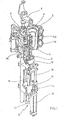
- the basic structure of a device for forming preforms (1) in container (2) is in Fig. 1 and in Fig. 2 shown.
- the device for forming the container (2) consists essentially of a blowing station (3), which is provided with a blow mold (4) into which a preform (1) can be inserted.
- the preform (1) may be an injection-molded part of polyethylene terephthalate.
- the blow mold (4) consists of mold halves (5, 6) and a bottom part (7) which is a lifting device (8) is positionable.
- the preform (1) can be held in the region of the blowing station (3) by a transport mandrel (9) which, together with the preform (1), passes through a plurality of treatment stations within the device. But it is also possible to use the preform (1), for example via pliers or other handling means directly into the blow mold (4).
- a connecting piston (10) is arranged, which feeds the preform (1) compressed air and at the same time makes a seal relative to the transport mandrel (9).
- a connecting piston (10) is arranged, which feeds the preform (1) compressed air and at the same time makes a seal relative to the transport mandrel (9).
- a stretching of the preform (1) takes place in this embodiment by means of a stretching rod (11), which is positioned by a cylinder (12).
- a mechanical positioning of the stretch rod (11) is carried out over curve segments, which are acted upon by Abgriff rollers.
- the use of curve segments is particular then expedient if a plurality of blowing stations (3) are arranged on a rotating blowing wheel
- the stretching system is designed such that a tandem arrangement of two cylinders (12) is provided. From a primary cylinder (13), the stretch rod (11) is first moved to the area of a bottom (14) of the preform (1) before the beginning of the actual stretching operation.
- the primary cylinder (13) with extended stretching rod together with a carriage (15) carrying the primary cylinder (13) is positioned by a secondary cylinder (16) or via a cam control.
- the secondary cylinder (16) in such a cam-controlled manner that a current stretching position is predetermined by a guide roller (17) which slides along a curved path during the execution of the stretching process.
- the guide roller (17) is pressed by the secondary cylinder (16) against the guideway.
- the carriage (15) slides along two guide elements (18).
- the carriers (19, 20) are locked relative to one another by means of a locking device (20).
- Fig. 2 shows in addition to the blown container (2) and dashed lines drawn the preform (1) and schematically a developing container bladder (23).
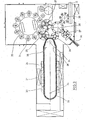
- Fig. 3 shows the basic structure of a blow molding machine, which is provided with a heating section (24) and a rotating blowing wheel (25).
- a preform input (26) the preforms (1) are transported by transfer wheels (27, 28, 29) into the region of the heating path (24).
- heating element (30) and blower (31) are arranged to temper the preforms (1).
- After a sufficient temperature control of the preforms (1) they are transferred to the blowing wheel (25), in the region of which the blowing stations (3) are arranged.
- the finished blown containers (2) are fed by further transfer wheels to a delivery line (32).
- thermoplastic material different plastics can be used.
- PET, PEN or PP can be used.
- the expansion of the preform (1) during the orientation process is carried out by compressed air supply.
- the Compressed air supply is in a Vorblasphase in which gas, for example, compressed air, is supplied at a low pressure level and divided into a subsequent Hauptblasphase in which gas is supplied at a higher pressure level.
- compressed air is typically used at a pressure in the interval of 10 bar to 25 bar and during the main blowing phase compressed air is supplied at a pressure in the interval of 25 bar to 40 bar.
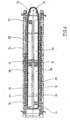
- the heating section (24) is formed of a plurality of revolving transport elements (33) which are strung together like a chain and guided by guide wheels (34).
- guide wheels (34) In particular, it is envisaged to open a substantially rectangular basic contour by the chain-like arrangement.
- the heating section (24) in the region of the transfer wheel (29) and an input wheel (35) facing extension of the heating section (24) a single relatively large-sized guide wheel (34) and in the region of adjacent deflections two comparatively smaller dimensioned guide wheels (36) used , In principle, however, any other guides are conceivable.
- modified Schwarzstrekke (24) can be tempered by the larger number of heating elements (30) a larger amount of preforms (1) per unit time.
- the fans (31) introduce cooling air into the region of cooling air ducts (39), which are opposite to the associated heating elements (30) and emit the cooling air via outflow openings. By arranging the outflow directions, a flow direction for the cooling air is realized substantially transversely to a transport direction of the preforms (1).
- the cooling air channels (39) can provide reflectors for the heating radiation in the area of the heating elements (30) opposite surfaces, it is also possible to realize a cooling of the heating elements (30) via the discharged cooling air.
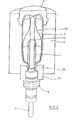
- Fig. 5 shows a schematic representation of a heating element (30), which is provided with a plurality of stacked radiant heater (41). Using the radiant heaters (41), it is possible to produce a predetermined temperature profile in the direction of a longitudinal axis (42) of the preform (1). When performing a stretching process is substantially subjecting a stretch region (43) of the preform (1) to biaxial orientation.
- Fig. 6 shows a schematic representation of a measuring device (44) with a plurality of superimposed sensors (45) for detecting a wall thickness of the container (2).
- the stretch region (43) of the preform (1) was converted as a result of the stretching and blowing process in an orientation region (46) of the container (2).
- the stretch region (43) of the preform (1) has an initial length (47) and the orientation region (46) of the container (2) is provided with a product length (48).
- the quotient of the product length (48) and the initial length (47) gives the realized stretching factor.
- the container (2) has a container longitudinal axis (49), in the direction behind which the sensors (45) are arranged.
- a sensor distance (50) results from a Schustrahlerabstand (51) multiplied by the stretching factor.
- Fig. 7 shows a schematic representation of a blowing machine (52) in a relation to the representation in Fig. 3 highly simplified and schematized structure. It can be seen that a temperature sensor (53) for detecting a temperature of the preforms (1) in a transport direction of the preforms (1) in the region of the heating section (24) behind the heating elements (30) is arranged.
- the temperature sensor (53) is arranged as close as possible to the blowing wheel (25) in order to enable a temperature detection after carrying out thermal compensation processes within the wall of the preforms (1).
- a temperature sensor (53) for example, a pyrometer can be used become.
- a plurality of temperature sensors (53) one above the other in the direction of the longitudinal axis (42) of the preforms (1) in order to detect a temperature profile of the preforms (1). It proves to be particularly advantageous to position a plurality of temperature sensors (53) in each case at a height level of the radiant heaters (41) in order to be able to carry out a direct regulation of the individual radiant heaters (41).
- the measuring device (44) can be arranged, for example, in the region of a removal device (54) which guides the blown containers (2) out of the region of the blowing wheel (25).
- Fig. 8 shows a schematic representation of a control system for the heating elements (30) and the radiant heater (41).
- the control system is designed in the form of a cascade control.
- An external control circuit detects behind the blow station (3) via the measuring device (44) the wall thickness (2) of the container (2) at a predetermined height level and supplies this actual value to the input of a wall thickness regulator (55).
- Immediate input value for the wall thickness controller (55) is the control difference between a given wall thickness and the measured wall thickness detected.
- An output value of the wall thickness controller (55) provides the set point for an internal temperature control loop.
- a temperature controller (56) has as direct control value the difference between the output value of the wall thickness regulator (55) and a temperature value of the preform (1) detected by the temperature sensor (53) fed to a predetermined height level.
- each of the radiant heaters (41) is a in Fig. 8 assigned control structure assigned.
- control of the inner loop is omitted and there is only a control in terms of wall thickness without metrological detection and control of temperature.
- at least one of the controllers (55, 56) is designed with an integral behavior in order to avoid control differences.
- the control takes into account a dead time behavior of the control system due to the transport path lengths of the preforms (1) or or container (2). In this case, it is taken into account that there is a delay, known as a function of the transport speed, between a manipulated variable change and a change in the output variable.
Landscapes
- Engineering & Computer Science (AREA)
- Manufacturing & Machinery (AREA)
- Mechanical Engineering (AREA)
- Blow-Moulding Or Thermoforming Of Plastics Or The Like (AREA)
Claims (19)
- Procédé de moulage par soufflage de récipients (2), dans le cadre duquel une préforme (1) en un matériau thermoplastique, après un conditionnement thermique le long d'un parcours dans une zone de chauffage (24), est étirée à l'intérieur d'un moule de soufflage (4) et, sous l'action d'une pression de soufflage, transformée en un récipient (2), le conditionnement thermique étant réalisé par plusieurs radiateurs de chauffage (41) positionnés l'un au dessus de l'autre, caractérisé en ce que, à l'issue du moulage par soufflage du récipient (2), une épaisseur de paroi est mesurée à au moins un niveau de hauteur du récipient (2) et qu'un radiateur de chauffage (41) affecté à ce niveau de hauteur est réglé quant à sa puissance de chauffage et que cette régulation fait appel à une épaisseur de paroi prescrite comme valeur de consigne et à l'épaisseur de paroi mesurée comme valeur effective.
- Procédé selon la revendication 1, caractérisé en ce que la mesure de l'épaisseur de paroi du récipient (2) est réalisée à plusieurs niveaux de hauteur différents.
- Procédé selon la revendication 1 ou 2, caractérisé en ce qu'au moins deux paires de systèmes de mesure (44) et de régulateurs (55) de l'épaisseur de paroi du récipient (2) respectivement agencés à des niveaux de hauteur correspondants sont respectivement intégrées dans une boucle d'asservissement d'un système de régulation d'épaisseur de paroi spécifique à un niveau de hauteur.
- Procédé selon l'une des revendications 1 à 3, caractérisé en ce qu'une mesure de la température des préformes (1) est effectuée.
- Procédé selon l'une des revendications 1 à 4, caractérisé en ce qu'une régulation de température et une régulation d'épaisseur de paroi sont effectuées sous forme de régulation en cascade.
- Procédé selon la revendication 5, caractérisé en ce que la régulation de température est effectuée dans une boucle d'asservissement intérieure de la régulation en cascade et la régulation d'épaisseur de paroi dans une boucle d'asservissement extérieure de la régulation en cascade.
- Procédé selon l'une des revendications 1 à 6, caractérisé en ce qu'une mesure de la température des préformes est effectuée derrière la zone de chauffage (24).
- Procédé selon l'une des revendications 1 à 7, caractérisé en ce que la mesure de la température des préformes (1) est effectuée, dans le sens de transport des préformes (1), entre la zone de chauffage (24) et une roue de soufflage (25).
- Procédé selon l'une des revendications 1 à 8, caractérisé en ce qu'une mesure de l'épaisseur de paroi est effectuée, dans le sens de transport, derrière la roue de soufflage (25).
- Procédé selon l'une des revendications 1 à 9, caractérisé en ce qu'une partie seulement des éléments de chauffage (30) de la zone de chauffage (24) est commandée par le régulateur d'épaisseur de paroi (55).
- Procédé selon la revendication 10, caractérisé en ce qu'au moins le dernier élément de chauffage (30), vu dans le sens de transport des préformes (1), est commandé par le régulateur d'épaisseur de paroi (55).
- Procédé selon l'une des revendications 1 à 11, caractérisé en ce qu'au moins deux éléments de chauffage (30) sont commandés parallèlement par le régulateur d'épaisseur de paroi (55).
- Procédé selon l'une des revendications 1 à 12, caractérisé en ce qu'au moins le premier élément de chauffage (30), vu dans le sens de transport des préformes (1), chauffe la préformes (1) à une température de base non réglée.
- Dispositif de moulage par soufflage de récipients (2) en un matériau thermoplastique présentant au moins une zone de chauffage (24) agencée le long d'un parcours d'une préforme (1) et une station de soufflage (3) équipée d'un moule de soufflage (4) et dont la zone de chauffage (24) présente au moins un élément de chauffage avec au moins deux radiateurs de chauffage (41) placés l'un au-dessus de l'autre, ces radiateurs de chauffage (41) étant branchés sur une commande connectée à au moins un capteur (45) destiné à saisir l'épaisseur de paroi du récipient (2), caractérisé en ce que le capteur (42) est placé à un niveau de hauteur correspondant à un niveau de hauteur de l'un des au moins deux radiateurs de chauffage (41), cette correspondance tenant compte d'un facteur d'étirage basé sur le rapport entre la longueur de la zone étirée du récipient (2) et la longueur de la zone correspondante de la préforme (1), et en ce que la puissance de chauffage d'un radiateur de chauffage (41) affecté à ce niveau de hauteur est réglable par la commande et que cette régulation fait appel à une épaisseur de paroi prescrite comme valeur de consigne et à l'épaisseur de paroi commune comme valeur effective.
- Dispositif selon la revendication 14, caractérisé en ce que plusieurs capteurs (45) sont agencés à des niveaux de hauteur différents les uns par rapport aux autres.
- Dispositif selon la revendication 14 ou 15, caractérisé en ce que des paires de capteurs (45) et de radiateurs de chauffage (41) affectées à différents niveaux de hauteur sont respectivement agencées dans une boucle d'asservissement affectée à chacun de ces niveaux de hauteur.
- Dispositif selon l'une des revendications 14 à 16, caractérisé en ce que la commande présente au moins un capteur de température (53).
- Dispositif selon l'une des revendications 14 à 17, caractérisé en ce qu'au moins un capteur de température (53) et au moins un capteur (45) de mesure de l'épaisseur de paroi sont agencés avec un régulateur d'épaisseur de paroi (55) et un régulateur de température (56) pour former ensemble une régulation en cascade.
- Dispositif selon la revendication 18, caractérisé en ce que le capteur de température (53) et le régulateur de température (56) sont agencés dans une boucle d'asservissement intérieure de la régulation en cascade et que le capteur (45) de régulation d'épaisseur de paroi et le régulateur d'épaisseur de paroi (55) forment des partie d'une boucle d'asservissement extérieure de la régulation en cascade.
Applications Claiming Priority (2)
| Application Number | Priority Date | Filing Date | Title |
|---|---|---|---|
| DE102006014389A DE102006014389A1 (de) | 2006-03-29 | 2006-03-29 | Verfahren und Vorrichtung zur Blasformung von Behältern |
| PCT/DE2007/000331 WO2007110018A1 (fr) | 2006-03-29 | 2007-02-22 | PROCEDE ET DISPOSITIF DE FORMAge-SOUFFLAGE DE RECIPIENTS PAR RECOURS A LA MESURE DE L'EPAISSEUR DE PAROIS DE L'OBJET FACONNE |
Publications (2)
| Publication Number | Publication Date |
|---|---|
| EP1998950A1 EP1998950A1 (fr) | 2008-12-10 |
| EP1998950B1 true EP1998950B1 (fr) | 2014-10-29 |
Family
ID=38164407
Family Applications (1)
| Application Number | Title | Priority Date | Filing Date |
|---|---|---|---|
| EP07721945.9A Not-in-force EP1998950B1 (fr) | 2006-03-29 | 2007-02-22 | PROCEDE ET DISPOSITIF DE FORMAge-SOUFFLAGE DE RECIPIENTS PAR RECOURS A LA MESURE DE L'EPAISSEUR DE PAROIS DE L'OBJET FACONNE |
Country Status (6)
| Country | Link |
|---|---|
| US (1) | US7887742B2 (fr) |
| EP (1) | EP1998950B1 (fr) |
| JP (1) | JP5401305B2 (fr) |
| CN (1) | CN101432122B (fr) |
| DE (1) | DE102006014389A1 (fr) |
| WO (1) | WO2007110018A1 (fr) |
Cited By (6)
| Publication number | Priority date | Publication date | Assignee | Title |
|---|---|---|---|---|
| EP3397562B1 (fr) | 2015-12-30 | 2020-02-26 | Tetra Laval Holdings & Finance S.A. | Procédés et appareils de garantie de qualité d'emballage |
| EP3397560B1 (fr) | 2015-12-30 | 2020-05-06 | Tetra Laval Holdings & Finance S.A. | Procédés et appareils de contrôle de qualité guidé d'un système d'emballage |
| DE102022121954A1 (de) | 2022-08-31 | 2024-02-29 | Krones Aktiengesellschaft | Verfahren und Vorrichtung zum Minimieren einer Abweichung eines physischen Parameters eines blasgeformten Behälters von einem Sollwert |
| DE102022122969A1 (de) * | 2022-09-09 | 2024-03-14 | Krones Aktiengesellschaft | Vorrichtung und Verfahren zur Herstellung von Behältern |
| US12170849B2 (en) | 2022-02-04 | 2024-12-17 | Applied Materials, Inc. | Pulsed illumination for fluid inspection |
| EP4620652A1 (fr) * | 2024-03-21 | 2025-09-24 | Sidel Participations | Procédé de régulation d'une installation de production de récipients |
Families Citing this family (18)
| Publication number | Priority date | Publication date | Assignee | Title |
|---|---|---|---|---|
| DE102007046387A1 (de) * | 2007-09-21 | 2009-04-02 | Khs Corpoplast Gmbh & Co. Kg | Verfahren und Vorrichtung zur Blasformung von Behältern |
| DE102008013419A1 (de) * | 2008-03-06 | 2009-09-10 | Khs Corpoplast Gmbh & Co. Kg | Verfahren und Vorrichtung zur Blasformung von Behältern |
| DE102008057999A1 (de) * | 2008-11-13 | 2010-05-20 | Khs Corpoplast Gmbh & Co. Kg | Verfahren und Vorrichtung zur Blasformung von Behältern |
| DE102009040803A1 (de) * | 2009-08-25 | 2011-04-14 | Khs Corpoplast Gmbh & Co. Kg | Verfahren und Vorrichtung zur Blasformung von Behältern |
| US9146099B2 (en) * | 2010-07-07 | 2015-09-29 | Graham Packaging Company, L.P. | Method and system for thermally monitoring process for forming plastic blow-molded containers |
| DE102017217468B4 (de) | 2017-09-29 | 2021-01-14 | Kautex Textron Gmbh & Co. Kg | Verfahren zur herstellung von kunststoffhohlkörpern |
| DE102017010970A1 (de) | 2017-11-27 | 2019-05-29 | Khs Corpoplast Gmbh | Temperiervorrichtung für die Temperaturkonditionierung von Vorformlingen und Verfahren zum Betreiben einer solchen Temperiervorrichtung |
| CN108000847B (zh) * | 2017-12-07 | 2024-07-23 | 锦西化工研究院有限公司 | 一种无模具吹塑多曲率成型件的方法及装置 |
| CN113165253B (zh) * | 2018-12-04 | 2023-09-01 | 大日本印刷株式会社 | 塑料瓶制造装置以及塑料瓶制造方法 |
| JP6806350B1 (ja) * | 2020-01-24 | 2021-01-06 | タマダ株式会社 | 2軸延伸ブロー成形機の加熱装置及び2軸延伸ブロー成形機 |
| WO2022014716A1 (fr) * | 2020-07-17 | 2022-01-20 | 日精エー・エス・ビー機械株式会社 | Procédé de commande de dispositif de fabrication, procédé de fabrication de contenant en résine, dispositif de commande de dispositif de fabrication et dispositif de fabrication de contenant en résine présentant ce dernier |
| DE102020123163A1 (de) | 2020-09-04 | 2022-03-10 | Krones Aktiengesellschaft | Vorrichtung und Verfahren zum Erwärmen von Kunststoffvorformlingen mit ortaufgelöster Temperaturerfassung |
| CN114043706A (zh) * | 2021-11-15 | 2022-02-15 | 襄阳光瑞汽车零部件有限公司 | 一种预埋固定镶件式一体吹塑成型工艺 |
| FR3131555B1 (fr) | 2021-12-30 | 2024-09-06 | Sidel Participations | Procédé de régulation d’une installation de production de récipients |
| FR3131554B1 (fr) | 2021-12-30 | 2024-09-06 | Sidel Participations | Procédé de régulation d’une unité de chauffage d’une installation de production de récipients |
| FR3131556B1 (fr) | 2021-12-30 | 2025-07-18 | Sidel Participations | Procédé de régulation d’une installation de production de récipients |
| EP4547469A1 (fr) * | 2022-06-30 | 2025-05-07 | Discma AG | Procédé de formation de récipients à l'aide d'une cellule de fabrication |
| FR3153554A1 (fr) | 2023-09-29 | 2025-04-04 | Sidel Participations | Procédé de régulation d’une installation de production de récipients |
Family Cites Families (12)
| Publication number | Priority date | Publication date | Assignee | Title |
|---|---|---|---|---|
| AT521B (fr) | 1899-11-12 | 1899-11-10 | Wilhelm Adolf August Roeper | |
| DE2352926A1 (de) | 1973-10-22 | 1975-04-24 | Heidenreich & Harbeck Gmbh | Verfahren und vorrichtung zum erwaermen eines werkstueckes aus kunststoff |
| JPS5789929A (en) * | 1980-11-26 | 1982-06-04 | Dainippon Printing Co Ltd | Temperature controlling method of parison |
| JP3218670B2 (ja) * | 1992-03-30 | 2001-10-15 | 凸版印刷株式会社 | パリソンの温度調節方法 |
| DE4212583A1 (de) | 1992-04-15 | 1993-10-21 | Krupp Corpoplast Masch | Vorrichtung zur Blasformung |
| DE4340291A1 (de) | 1993-11-26 | 1995-06-01 | Krupp Corpoplast Masch | Mehrfachnutzung von Blasluft |
| AT521U1 (de) * | 1994-11-08 | 1995-12-27 | Kosme Etikettiertechnik Ges M | Verfahren zur einstellung von verfahrensparametern bei der herstellung von hohlkoerpern aus thermoplastischen vorformlingen sowie vorrichtung zur durchfuehrung des verfahrens |
| DE19843053A1 (de) * | 1998-09-19 | 2000-03-23 | Krupp Corpoplast Masch | Verfahren und Vorrichtung zur Steuerung eines Blasvorganges |
| DE19906438A1 (de) | 1999-02-16 | 2000-08-17 | Krupp Corpoplast Masch | Verfahren und Vorrichtung zur Übergabe von Behältern |
| US6620352B1 (en) * | 2000-07-27 | 2003-09-16 | Ball Corporation | Automated material distribution control for stretch blow molded articles |
| US6863860B1 (en) * | 2002-03-26 | 2005-03-08 | Agr International, Inc. | Method and apparatus for monitoring wall thickness of blow-molded plastic containers |
| CA2527707A1 (fr) * | 2003-06-10 | 2005-01-06 | Petwall, Llc | Systeme d'inspection et de gestion de la fabrication de recipients |
-
2006
- 2006-03-29 DE DE102006014389A patent/DE102006014389A1/de not_active Withdrawn
-
2007
- 2007-02-22 WO PCT/DE2007/000331 patent/WO2007110018A1/fr not_active Ceased
- 2007-02-22 JP JP2009501830A patent/JP5401305B2/ja not_active Expired - Fee Related
- 2007-02-22 EP EP07721945.9A patent/EP1998950B1/fr not_active Not-in-force
- 2007-02-22 CN CN2007800122384A patent/CN101432122B/zh not_active Expired - Fee Related
- 2007-02-22 US US12/225,607 patent/US7887742B2/en active Active
Cited By (8)
| Publication number | Priority date | Publication date | Assignee | Title |
|---|---|---|---|---|
| EP3397562B1 (fr) | 2015-12-30 | 2020-02-26 | Tetra Laval Holdings & Finance S.A. | Procédés et appareils de garantie de qualité d'emballage |
| EP3397560B1 (fr) | 2015-12-30 | 2020-05-06 | Tetra Laval Holdings & Finance S.A. | Procédés et appareils de contrôle de qualité guidé d'un système d'emballage |
| US12170849B2 (en) | 2022-02-04 | 2024-12-17 | Applied Materials, Inc. | Pulsed illumination for fluid inspection |
| DE102022121954A1 (de) | 2022-08-31 | 2024-02-29 | Krones Aktiengesellschaft | Verfahren und Vorrichtung zum Minimieren einer Abweichung eines physischen Parameters eines blasgeformten Behälters von einem Sollwert |
| EP4331809A1 (fr) | 2022-08-31 | 2024-03-06 | KRONES Aktiengesellschaft | Procédé et dispositif pour minimiser l'écart d'un paramètre physique d'un récipient moulé par soufflage d'une valeur de consigne |
| DE102022122969A1 (de) * | 2022-09-09 | 2024-03-14 | Krones Aktiengesellschaft | Vorrichtung und Verfahren zur Herstellung von Behältern |
| EP4620652A1 (fr) * | 2024-03-21 | 2025-09-24 | Sidel Participations | Procédé de régulation d'une installation de production de récipients |
| FR3160347A1 (fr) * | 2024-03-21 | 2025-09-26 | Sidel Participations | Procédé de régulation d’une installation de production de récipients |
Also Published As
| Publication number | Publication date |
|---|---|
| JP5401305B2 (ja) | 2014-01-29 |
| DE102006014389A1 (de) | 2007-10-25 |
| CN101432122B (zh) | 2012-08-01 |
| WO2007110018A9 (fr) | 2009-02-26 |
| US7887742B2 (en) | 2011-02-15 |
| WO2007110018A1 (fr) | 2007-10-04 |
| JP2009531196A (ja) | 2009-09-03 |
| US20100007060A1 (en) | 2010-01-14 |
| EP1998950A1 (fr) | 2008-12-10 |
| CN101432122A (zh) | 2009-05-13 |
Similar Documents
| Publication | Publication Date | Title |
|---|---|---|
| EP1998950B1 (fr) | PROCEDE ET DISPOSITIF DE FORMAge-SOUFFLAGE DE RECIPIENTS PAR RECOURS A LA MESURE DE L'EPAISSEUR DE PAROIS DE L'OBJET FACONNE | |
| EP2352633B1 (fr) | Procédé et dispositif de moulage de contenants par soufflage | |
| EP2247429B1 (fr) | Procédé et dispositif de moulage par soufflage de récipients | |
| EP2470348B1 (fr) | Procédé et dispositif de moulage par soufflage de contenants | |
| EP2188108B2 (fr) | Procédé de moulage par soufflage de récipients | |
| EP2081752B1 (fr) | Procédé et dispositif de formage-soufflage de récipients | |
| EP2307185B1 (fr) | Procédé et appareil pour moulage par soufflage des recipients | |
| WO2013023789A1 (fr) | Procédé et dispositif de moulage de récipients par soufflage | |
| WO2011091780A2 (fr) | Procédé et dispositif de moulage par soufflage de récipients | |
| EP1910056B1 (fr) | Procede et dispositif de positionnement d'un composant | |
| DE102007016027A1 (de) | Verfahren und Vorrichtung zur Blasformung von Behältern | |
| EP1574318B1 (fr) | Procédé et appareil de formage de récipients par soufflage | |
| EP1732743B1 (fr) | Procede et dispositif de moulage de contenants par soufflage, faisant appel a une vitesse d'augmentation de pression reduite | |
| EP1566258B1 (fr) | Appareil pour l'usinage de pièces | |
| EP2129508B1 (fr) | Procédé de moulage par soufflage de contenants | |
| DE102010049505B4 (de) | Verfahren zur Herstellung von Behältern sowie blasgeformter Behälter | |
| WO2012116684A1 (fr) | Procédé et dispositif pour la manipulation d'ébauches | |
| EP1473139A1 (fr) | Procédé et appareil de formage de récipients par soufflage | |
| DE102006004940A1 (de) | Verfahren und Vorrichtung zur Blasformung von Behältern | |
| DE102004050531A1 (de) | Verfahren und Vorrichtung zur Blasformung von Behältern |
Legal Events
| Date | Code | Title | Description |
|---|---|---|---|
| PUAI | Public reference made under article 153(3) epc to a published international application that has entered the european phase |
Free format text: ORIGINAL CODE: 0009012 |
|
| 17P | Request for examination filed |
Effective date: 20080812 |
|
| AK | Designated contracting states |
Kind code of ref document: A1 Designated state(s): AT BE BG CH CY CZ DE DK EE ES FI FR GB GR HU IE IS IT LI LT LU LV MC NL PL PT RO SE SI SK TR |
|
| DAX | Request for extension of the european patent (deleted) | ||
| 17Q | First examination report despatched |
Effective date: 20090603 |
|
| RAP1 | Party data changed (applicant data changed or rights of an application transferred) |
Owner name: KHS CORPOPLAST GMBH |
|
| GRAP | Despatch of communication of intention to grant a patent |
Free format text: ORIGINAL CODE: EPIDOSNIGR1 |
|
| INTG | Intention to grant announced |
Effective date: 20140612 |
|
| GRAS | Grant fee paid |
Free format text: ORIGINAL CODE: EPIDOSNIGR3 |
|
| GRAA | (expected) grant |
Free format text: ORIGINAL CODE: 0009210 |
|
| AK | Designated contracting states |
Kind code of ref document: B1 Designated state(s): AT BE BG CH CY CZ DE DK EE ES FI FR GB GR HU IE IS IT LI LT LU LV MC NL PL PT RO SE SI SK TR |
|
| REG | Reference to a national code |
Ref country code: GB Ref legal event code: FG4D Free format text: NOT ENGLISH |
|
| REG | Reference to a national code |
Ref country code: CH Ref legal event code: EP |
|
| REG | Reference to a national code |
Ref country code: AT Ref legal event code: REF Ref document number: 693347 Country of ref document: AT Kind code of ref document: T Effective date: 20141115 |
|
| REG | Reference to a national code |
Ref country code: IE Ref legal event code: FG4D Free format text: LANGUAGE OF EP DOCUMENT: GERMAN |
|
| REG | Reference to a national code |
Ref country code: DE Ref legal event code: R096 Ref document number: 502007013540 Country of ref document: DE Effective date: 20141211 |
|
| REG | Reference to a national code |
Ref country code: FR Ref legal event code: PLFP Year of fee payment: 9 |
|
| REG | Reference to a national code |
Ref country code: NL Ref legal event code: VDEP Effective date: 20141029 |
|
| REG | Reference to a national code |
Ref country code: LT Ref legal event code: MG4D |
|
| PG25 | Lapsed in a contracting state [announced via postgrant information from national office to epo] |
Ref country code: PT Free format text: LAPSE BECAUSE OF FAILURE TO SUBMIT A TRANSLATION OF THE DESCRIPTION OR TO PAY THE FEE WITHIN THE PRESCRIBED TIME-LIMIT Effective date: 20150302 Ref country code: ES Free format text: LAPSE BECAUSE OF FAILURE TO SUBMIT A TRANSLATION OF THE DESCRIPTION OR TO PAY THE FEE WITHIN THE PRESCRIBED TIME-LIMIT Effective date: 20141029 Ref country code: IS Free format text: LAPSE BECAUSE OF FAILURE TO SUBMIT A TRANSLATION OF THE DESCRIPTION OR TO PAY THE FEE WITHIN THE PRESCRIBED TIME-LIMIT Effective date: 20150228 Ref country code: LT Free format text: LAPSE BECAUSE OF FAILURE TO SUBMIT A TRANSLATION OF THE DESCRIPTION OR TO PAY THE FEE WITHIN THE PRESCRIBED TIME-LIMIT Effective date: 20141029 Ref country code: FI Free format text: LAPSE BECAUSE OF FAILURE TO SUBMIT A TRANSLATION OF THE DESCRIPTION OR TO PAY THE FEE WITHIN THE PRESCRIBED TIME-LIMIT Effective date: 20141029 Ref country code: NL Free format text: LAPSE BECAUSE OF FAILURE TO SUBMIT A TRANSLATION OF THE DESCRIPTION OR TO PAY THE FEE WITHIN THE PRESCRIBED TIME-LIMIT Effective date: 20141029 |
|
| PG25 | Lapsed in a contracting state [announced via postgrant information from national office to epo] |
Ref country code: CY Free format text: LAPSE BECAUSE OF FAILURE TO SUBMIT A TRANSLATION OF THE DESCRIPTION OR TO PAY THE FEE WITHIN THE PRESCRIBED TIME-LIMIT Effective date: 20141029 Ref country code: SE Free format text: LAPSE BECAUSE OF FAILURE TO SUBMIT A TRANSLATION OF THE DESCRIPTION OR TO PAY THE FEE WITHIN THE PRESCRIBED TIME-LIMIT Effective date: 20141029 Ref country code: PL Free format text: LAPSE BECAUSE OF FAILURE TO SUBMIT A TRANSLATION OF THE DESCRIPTION OR TO PAY THE FEE WITHIN THE PRESCRIBED TIME-LIMIT Effective date: 20141029 Ref country code: GR Free format text: LAPSE BECAUSE OF FAILURE TO SUBMIT A TRANSLATION OF THE DESCRIPTION OR TO PAY THE FEE WITHIN THE PRESCRIBED TIME-LIMIT Effective date: 20150130 Ref country code: LV Free format text: LAPSE BECAUSE OF FAILURE TO SUBMIT A TRANSLATION OF THE DESCRIPTION OR TO PAY THE FEE WITHIN THE PRESCRIBED TIME-LIMIT Effective date: 20141029 |
|
| REG | Reference to a national code |
Ref country code: DE Ref legal event code: R026 Ref document number: 502007013540 Country of ref document: DE |
|
| PG25 | Lapsed in a contracting state [announced via postgrant information from national office to epo] |
Ref country code: EE Free format text: LAPSE BECAUSE OF FAILURE TO SUBMIT A TRANSLATION OF THE DESCRIPTION OR TO PAY THE FEE WITHIN THE PRESCRIBED TIME-LIMIT Effective date: 20141029 Ref country code: DK Free format text: LAPSE BECAUSE OF FAILURE TO SUBMIT A TRANSLATION OF THE DESCRIPTION OR TO PAY THE FEE WITHIN THE PRESCRIBED TIME-LIMIT Effective date: 20141029 Ref country code: SK Free format text: LAPSE BECAUSE OF FAILURE TO SUBMIT A TRANSLATION OF THE DESCRIPTION OR TO PAY THE FEE WITHIN THE PRESCRIBED TIME-LIMIT Effective date: 20141029 Ref country code: RO Free format text: LAPSE BECAUSE OF FAILURE TO SUBMIT A TRANSLATION OF THE DESCRIPTION OR TO PAY THE FEE WITHIN THE PRESCRIBED TIME-LIMIT Effective date: 20141029 Ref country code: CZ Free format text: LAPSE BECAUSE OF FAILURE TO SUBMIT A TRANSLATION OF THE DESCRIPTION OR TO PAY THE FEE WITHIN THE PRESCRIBED TIME-LIMIT Effective date: 20141029 |
|
| PLBI | Opposition filed |
Free format text: ORIGINAL CODE: 0009260 |
|
| 26 | Opposition filed |
Opponent name: KRONES AG Effective date: 20150729 |
|
| PLAX | Notice of opposition and request to file observation + time limit sent |
Free format text: ORIGINAL CODE: EPIDOSNOBS2 |
|
| PG25 | Lapsed in a contracting state [announced via postgrant information from national office to epo] |
Ref country code: LU Free format text: LAPSE BECAUSE OF FAILURE TO SUBMIT A TRANSLATION OF THE DESCRIPTION OR TO PAY THE FEE WITHIN THE PRESCRIBED TIME-LIMIT Effective date: 20150222 |
|
| REG | Reference to a national code |
Ref country code: CH Ref legal event code: PL |
|
| GBPC | Gb: european patent ceased through non-payment of renewal fee |
Effective date: 20150222 |
|
| PG25 | Lapsed in a contracting state [announced via postgrant information from national office to epo] |
Ref country code: CH Free format text: LAPSE BECAUSE OF NON-PAYMENT OF DUE FEES Effective date: 20150228 Ref country code: LI Free format text: LAPSE BECAUSE OF NON-PAYMENT OF DUE FEES Effective date: 20150228 Ref country code: MC Free format text: LAPSE BECAUSE OF FAILURE TO SUBMIT A TRANSLATION OF THE DESCRIPTION OR TO PAY THE FEE WITHIN THE PRESCRIBED TIME-LIMIT Effective date: 20141029 |
|
| REG | Reference to a national code |
Ref country code: IE Ref legal event code: MM4A |
|
| PLAF | Information modified related to communication of a notice of opposition and request to file observations + time limit |
Free format text: ORIGINAL CODE: EPIDOSCOBS2 |
|
| PG25 | Lapsed in a contracting state [announced via postgrant information from national office to epo] |
Ref country code: IE Free format text: LAPSE BECAUSE OF NON-PAYMENT OF DUE FEES Effective date: 20150222 Ref country code: GB Free format text: LAPSE BECAUSE OF NON-PAYMENT OF DUE FEES Effective date: 20150222 |
|
| REG | Reference to a national code |
Ref country code: FR Ref legal event code: PLFP Year of fee payment: 10 |
|
| PG25 | Lapsed in a contracting state [announced via postgrant information from national office to epo] |
Ref country code: SI Free format text: LAPSE BECAUSE OF FAILURE TO SUBMIT A TRANSLATION OF THE DESCRIPTION OR TO PAY THE FEE WITHIN THE PRESCRIBED TIME-LIMIT Effective date: 20141029 |
|
| PLBB | Reply of patent proprietor to notice(s) of opposition received |
Free format text: ORIGINAL CODE: EPIDOSNOBS3 |
|
| REG | Reference to a national code |
Ref country code: AT Ref legal event code: MM01 Ref document number: 693347 Country of ref document: AT Kind code of ref document: T Effective date: 20150222 |
|
| PG25 | Lapsed in a contracting state [announced via postgrant information from national office to epo] |
Ref country code: AT Free format text: LAPSE BECAUSE OF NON-PAYMENT OF DUE FEES Effective date: 20150222 |
|
| REG | Reference to a national code |
Ref country code: FR Ref legal event code: PLFP Year of fee payment: 11 |
|
| PG25 | Lapsed in a contracting state [announced via postgrant information from national office to epo] |
Ref country code: HU Free format text: LAPSE BECAUSE OF FAILURE TO SUBMIT A TRANSLATION OF THE DESCRIPTION OR TO PAY THE FEE WITHIN THE PRESCRIBED TIME-LIMIT; INVALID AB INITIO Effective date: 20070222 Ref country code: BG Free format text: LAPSE BECAUSE OF FAILURE TO SUBMIT A TRANSLATION OF THE DESCRIPTION OR TO PAY THE FEE WITHIN THE PRESCRIBED TIME-LIMIT Effective date: 20141029 |
|
| PG25 | Lapsed in a contracting state [announced via postgrant information from national office to epo] |
Ref country code: BE Free format text: LAPSE BECAUSE OF NON-PAYMENT OF DUE FEES Effective date: 20150228 |
|
| PG25 | Lapsed in a contracting state [announced via postgrant information from national office to epo] |
Ref country code: TR Free format text: LAPSE BECAUSE OF FAILURE TO SUBMIT A TRANSLATION OF THE DESCRIPTION OR TO PAY THE FEE WITHIN THE PRESCRIBED TIME-LIMIT Effective date: 20141029 |
|
| REG | Reference to a national code |
Ref country code: FR Ref legal event code: PLFP Year of fee payment: 12 |
|
| PLCK | Communication despatched that opposition was rejected |
Free format text: ORIGINAL CODE: EPIDOSNREJ1 |
|
| STAA | Information on the status of an ep patent application or granted ep patent |
Free format text: STATUS: THE PATENT HAS BEEN GRANTED |
|
| APBM | Appeal reference recorded |
Free format text: ORIGINAL CODE: EPIDOSNREFNO |
|
| APBP | Date of receipt of notice of appeal recorded |
Free format text: ORIGINAL CODE: EPIDOSNNOA2O |
|
| APAH | Appeal reference modified |
Free format text: ORIGINAL CODE: EPIDOSCREFNO |
|
| APBQ | Date of receipt of statement of grounds of appeal recorded |
Free format text: ORIGINAL CODE: EPIDOSNNOA3O |
|
| REG | Reference to a national code |
Ref country code: DE Ref legal event code: R082 Ref document number: 502007013540 Country of ref document: DE Ref country code: DE Ref legal event code: R082 Ref document number: 502007013540 Country of ref document: DE Representative=s name: EISENFUEHR SPEISER PATENTANWAELTE RECHTSANWAEL, DE |
|
| APAH | Appeal reference modified |
Free format text: ORIGINAL CODE: EPIDOSCREFNO |
|
| RAP2 | Party data changed (patent owner data changed or rights of a patent transferred) |
Owner name: KHS GMBH |
|
| REG | Reference to a national code |
Ref country code: DE Ref legal event code: R082 Ref document number: 502007013540 Country of ref document: DE Representative=s name: EISENFUEHR SPEISER PATENTANWAELTE RECHTSANWAEL, DE Ref country code: DE Ref legal event code: R081 Ref document number: 502007013540 Country of ref document: DE Owner name: KHS GMBH, DE Free format text: FORMER OWNER: KHS CORPOPLAST GMBH, 22145 HAMBURG, DE Ref country code: DE Ref legal event code: R082 Ref document number: 502007013540 Country of ref document: DE |
|
| REG | Reference to a national code |
Ref country code: DE Ref legal event code: R082 Ref document number: 502007013540 Country of ref document: DE Representative=s name: EISENFUEHR SPEISER PATENTANWAELTE RECHTSANWAEL, DE |
|
| REG | Reference to a national code |
Ref country code: DE Ref legal event code: R100 Ref document number: 502007013540 Country of ref document: DE |
|
| APBU | Appeal procedure closed |
Free format text: ORIGINAL CODE: EPIDOSNNOA9O |
|
| PLBN | Opposition rejected |
Free format text: ORIGINAL CODE: 0009273 |
|
| STAA | Information on the status of an ep patent application or granted ep patent |
Free format text: STATUS: OPPOSITION REJECTED |
|
| 27O | Opposition rejected |
Effective date: 20230215 |
|
| PGFP | Annual fee paid to national office [announced via postgrant information from national office to epo] |
Ref country code: FR Payment date: 20230220 Year of fee payment: 17 |
|
| PGFP | Annual fee paid to national office [announced via postgrant information from national office to epo] |
Ref country code: IT Payment date: 20230223 Year of fee payment: 17 Ref country code: DE Payment date: 20230216 Year of fee payment: 17 |
|
| REG | Reference to a national code |
Ref country code: DE Ref legal event code: R119 Ref document number: 502007013540 Country of ref document: DE |
|
| PG25 | Lapsed in a contracting state [announced via postgrant information from national office to epo] |
Ref country code: DE Free format text: LAPSE BECAUSE OF NON-PAYMENT OF DUE FEES Effective date: 20240903 |
|
| PG25 | Lapsed in a contracting state [announced via postgrant information from national office to epo] |
Ref country code: FR Free format text: LAPSE BECAUSE OF NON-PAYMENT OF DUE FEES Effective date: 20240229 |
|
| PG25 | Lapsed in a contracting state [announced via postgrant information from national office to epo] |
Ref country code: FR Free format text: LAPSE BECAUSE OF NON-PAYMENT OF DUE FEES Effective date: 20240229 Ref country code: DE Free format text: LAPSE BECAUSE OF NON-PAYMENT OF DUE FEES Effective date: 20240903 |
|
| PG25 | Lapsed in a contracting state [announced via postgrant information from national office to epo] |
Ref country code: IT Free format text: LAPSE BECAUSE OF NON-PAYMENT OF DUE FEES Effective date: 20240222 |