EP1574318B1 - Procédé et appareil de formage de récipients par soufflage - Google Patents
Procédé et appareil de formage de récipients par soufflage Download PDFInfo
- Publication number
- EP1574318B1 EP1574318B1 EP05000443A EP05000443A EP1574318B1 EP 1574318 B1 EP1574318 B1 EP 1574318B1 EP 05000443 A EP05000443 A EP 05000443A EP 05000443 A EP05000443 A EP 05000443A EP 1574318 B1 EP1574318 B1 EP 1574318B1
- Authority
- EP
- European Patent Office
- Prior art keywords
- stretching rod
- container
- blowing
- blown gas
- stretching
- Prior art date
- Legal status (The legal status is an assumption and is not a legal conclusion. Google has not performed a legal analysis and makes no representation as to the accuracy of the status listed.)
- Active
Links
- 238000000071 blow moulding Methods 0.000 title claims abstract description 15
- 238000000034 method Methods 0.000 title claims description 27
- 238000007664 blowing Methods 0.000 claims description 57
- 230000009467 reduction Effects 0.000 claims description 7
- 239000012815 thermoplastic material Substances 0.000 claims description 7
- 230000000694 effects Effects 0.000 claims description 3
- 230000003750 conditioning effect Effects 0.000 claims description 2
- 230000001960 triggered effect Effects 0.000 claims 2
- 238000010438 heat treatment Methods 0.000 description 14
- 230000008569 process Effects 0.000 description 11
- 238000001816 cooling Methods 0.000 description 8
- 230000008878 coupling Effects 0.000 description 5
- 238000010168 coupling process Methods 0.000 description 5
- 238000005859 coupling reaction Methods 0.000 description 5
- 229920000139 polyethylene terephthalate Polymers 0.000 description 4
- 239000005020 polyethylene terephthalate Substances 0.000 description 4
- 239000000969 carrier Substances 0.000 description 3
- 238000004519 manufacturing process Methods 0.000 description 3
- 238000000465 moulding Methods 0.000 description 3
- 238000010276 construction Methods 0.000 description 2
- 238000001746 injection moulding Methods 0.000 description 2
- -1 polyethylene terephthalate Polymers 0.000 description 2
- 235000013361 beverage Nutrition 0.000 description 1
- 230000008859 change Effects 0.000 description 1
- 230000001143 conditioned effect Effects 0.000 description 1
- 239000000463 material Substances 0.000 description 1
- 239000004033 plastic Substances 0.000 description 1
- 229920003023 plastic Polymers 0.000 description 1
- 230000005855 radiation Effects 0.000 description 1
- 230000003584 silencer Effects 0.000 description 1
- 239000007787 solid Substances 0.000 description 1
- 238000007711 solidification Methods 0.000 description 1
- 230000008023 solidification Effects 0.000 description 1
- 230000002123 temporal effect Effects 0.000 description 1
- 230000007704 transition Effects 0.000 description 1
Images


Classifications
-
- B—PERFORMING OPERATIONS; TRANSPORTING
- B29—WORKING OF PLASTICS; WORKING OF SUBSTANCES IN A PLASTIC STATE IN GENERAL
- B29C—SHAPING OR JOINING OF PLASTICS; SHAPING OF MATERIAL IN A PLASTIC STATE, NOT OTHERWISE PROVIDED FOR; AFTER-TREATMENT OF THE SHAPED PRODUCTS, e.g. REPAIRING
- B29C49/00—Blow-moulding, i.e. blowing a preform or parison to a desired shape within a mould; Apparatus therefor
- B29C49/08—Biaxial stretching during blow-moulding
- B29C49/10—Biaxial stretching during blow-moulding using mechanical means for prestretching
- B29C49/12—Stretching rods
-
- B—PERFORMING OPERATIONS; TRANSPORTING
- B29—WORKING OF PLASTICS; WORKING OF SUBSTANCES IN A PLASTIC STATE IN GENERAL
- B29C—SHAPING OR JOINING OF PLASTICS; SHAPING OF MATERIAL IN A PLASTIC STATE, NOT OTHERWISE PROVIDED FOR; AFTER-TREATMENT OF THE SHAPED PRODUCTS, e.g. REPAIRING
- B29C49/00—Blow-moulding, i.e. blowing a preform or parison to a desired shape within a mould; Apparatus therefor
- B29C49/42—Component parts, details or accessories; Auxiliary operations
- B29C49/78—Measuring, controlling or regulating
- B29C49/783—Measuring, controlling or regulating blowing pressure
-
- B—PERFORMING OPERATIONS; TRANSPORTING
- B29—WORKING OF PLASTICS; WORKING OF SUBSTANCES IN A PLASTIC STATE IN GENERAL
- B29C—SHAPING OR JOINING OF PLASTICS; SHAPING OF MATERIAL IN A PLASTIC STATE, NOT OTHERWISE PROVIDED FOR; AFTER-TREATMENT OF THE SHAPED PRODUCTS, e.g. REPAIRING
- B29C49/00—Blow-moulding, i.e. blowing a preform or parison to a desired shape within a mould; Apparatus therefor
- B29C49/42—Component parts, details or accessories; Auxiliary operations
- B29C49/62—Venting means
- B29C2049/6271—Venting means for venting blowing medium, e.g. using damper or silencer
-
- B—PERFORMING OPERATIONS; TRANSPORTING
- B29—WORKING OF PLASTICS; WORKING OF SUBSTANCES IN A PLASTIC STATE IN GENERAL
- B29C—SHAPING OR JOINING OF PLASTICS; SHAPING OF MATERIAL IN A PLASTIC STATE, NOT OTHERWISE PROVIDED FOR; AFTER-TREATMENT OF THE SHAPED PRODUCTS, e.g. REPAIRING
- B29C49/00—Blow-moulding, i.e. blowing a preform or parison to a desired shape within a mould; Apparatus therefor
- B29C49/42—Component parts, details or accessories; Auxiliary operations
- B29C49/78—Measuring, controlling or regulating
- B29C49/783—Measuring, controlling or regulating blowing pressure
- B29C2049/7831—Measuring, controlling or regulating blowing pressure characterised by pressure values or ranges
-
- B—PERFORMING OPERATIONS; TRANSPORTING
- B29—WORKING OF PLASTICS; WORKING OF SUBSTANCES IN A PLASTIC STATE IN GENERAL
- B29C—SHAPING OR JOINING OF PLASTICS; SHAPING OF MATERIAL IN A PLASTIC STATE, NOT OTHERWISE PROVIDED FOR; AFTER-TREATMENT OF THE SHAPED PRODUCTS, e.g. REPAIRING
- B29C49/00—Blow-moulding, i.e. blowing a preform or parison to a desired shape within a mould; Apparatus therefor
- B29C49/42—Component parts, details or accessories; Auxiliary operations
- B29C49/78—Measuring, controlling or regulating
- B29C49/783—Measuring, controlling or regulating blowing pressure
- B29C2049/7834—Pressure increase speed, e.g. dependent on stretch or position
-
- B—PERFORMING OPERATIONS; TRANSPORTING
- B29—WORKING OF PLASTICS; WORKING OF SUBSTANCES IN A PLASTIC STATE IN GENERAL
- B29C—SHAPING OR JOINING OF PLASTICS; SHAPING OF MATERIAL IN A PLASTIC STATE, NOT OTHERWISE PROVIDED FOR; AFTER-TREATMENT OF THE SHAPED PRODUCTS, e.g. REPAIRING
- B29C49/00—Blow-moulding, i.e. blowing a preform or parison to a desired shape within a mould; Apparatus therefor
- B29C49/42—Component parts, details or accessories; Auxiliary operations
- B29C49/78—Measuring, controlling or regulating
- B29C2049/7879—Stretching, e.g. stretch rod
-
- B—PERFORMING OPERATIONS; TRANSPORTING
- B29—WORKING OF PLASTICS; WORKING OF SUBSTANCES IN A PLASTIC STATE IN GENERAL
- B29C—SHAPING OR JOINING OF PLASTICS; SHAPING OF MATERIAL IN A PLASTIC STATE, NOT OTHERWISE PROVIDED FOR; AFTER-TREATMENT OF THE SHAPED PRODUCTS, e.g. REPAIRING
- B29C2949/00—Indexing scheme relating to blow-moulding
- B29C2949/07—Preforms or parisons characterised by their configuration
- B29C2949/0715—Preforms or parisons characterised by their configuration the preform having one end closed
-
- B—PERFORMING OPERATIONS; TRANSPORTING
- B29—WORKING OF PLASTICS; WORKING OF SUBSTANCES IN A PLASTIC STATE IN GENERAL
- B29C—SHAPING OR JOINING OF PLASTICS; SHAPING OF MATERIAL IN A PLASTIC STATE, NOT OTHERWISE PROVIDED FOR; AFTER-TREATMENT OF THE SHAPED PRODUCTS, e.g. REPAIRING
- B29C49/00—Blow-moulding, i.e. blowing a preform or parison to a desired shape within a mould; Apparatus therefor
- B29C49/02—Combined blow-moulding and manufacture of the preform or the parison
- B29C49/06—Injection blow-moulding
-
- B—PERFORMING OPERATIONS; TRANSPORTING
- B29—WORKING OF PLASTICS; WORKING OF SUBSTANCES IN A PLASTIC STATE IN GENERAL
- B29C—SHAPING OR JOINING OF PLASTICS; SHAPING OF MATERIAL IN A PLASTIC STATE, NOT OTHERWISE PROVIDED FOR; AFTER-TREATMENT OF THE SHAPED PRODUCTS, e.g. REPAIRING
- B29C49/00—Blow-moulding, i.e. blowing a preform or parison to a desired shape within a mould; Apparatus therefor
- B29C49/08—Biaxial stretching during blow-moulding
- B29C49/10—Biaxial stretching during blow-moulding using mechanical means for prestretching
- B29C49/122—Drive means therefor
- B29C49/1222—Pneumatic
-
- B—PERFORMING OPERATIONS; TRANSPORTING
- B29—WORKING OF PLASTICS; WORKING OF SUBSTANCES IN A PLASTIC STATE IN GENERAL
- B29C—SHAPING OR JOINING OF PLASTICS; SHAPING OF MATERIAL IN A PLASTIC STATE, NOT OTHERWISE PROVIDED FOR; AFTER-TREATMENT OF THE SHAPED PRODUCTS, e.g. REPAIRING
- B29C49/00—Blow-moulding, i.e. blowing a preform or parison to a desired shape within a mould; Apparatus therefor
- B29C49/08—Biaxial stretching during blow-moulding
- B29C49/10—Biaxial stretching during blow-moulding using mechanical means for prestretching
- B29C49/122—Drive means therefor
- B29C49/123—Electric drives, e.g. linear motors
-
- B—PERFORMING OPERATIONS; TRANSPORTING
- B29—WORKING OF PLASTICS; WORKING OF SUBSTANCES IN A PLASTIC STATE IN GENERAL
- B29C—SHAPING OR JOINING OF PLASTICS; SHAPING OF MATERIAL IN A PLASTIC STATE, NOT OTHERWISE PROVIDED FOR; AFTER-TREATMENT OF THE SHAPED PRODUCTS, e.g. REPAIRING
- B29C49/00—Blow-moulding, i.e. blowing a preform or parison to a desired shape within a mould; Apparatus therefor
- B29C49/42—Component parts, details or accessories; Auxiliary operations
- B29C49/4205—Handling means, e.g. transfer, loading or discharging means
- B29C49/42073—Grippers
- B29C49/42085—Grippers holding inside the neck
-
- B—PERFORMING OPERATIONS; TRANSPORTING
- B29—WORKING OF PLASTICS; WORKING OF SUBSTANCES IN A PLASTIC STATE IN GENERAL
- B29C—SHAPING OR JOINING OF PLASTICS; SHAPING OF MATERIAL IN A PLASTIC STATE, NOT OTHERWISE PROVIDED FOR; AFTER-TREATMENT OF THE SHAPED PRODUCTS, e.g. REPAIRING
- B29C49/00—Blow-moulding, i.e. blowing a preform or parison to a desired shape within a mould; Apparatus therefor
- B29C49/42—Component parts, details or accessories; Auxiliary operations
- B29C49/4205—Handling means, e.g. transfer, loading or discharging means
- B29C49/42073—Grippers
- B29C49/42087—Grippers holding outside the neck
-
- B—PERFORMING OPERATIONS; TRANSPORTING
- B29—WORKING OF PLASTICS; WORKING OF SUBSTANCES IN A PLASTIC STATE IN GENERAL
- B29C—SHAPING OR JOINING OF PLASTICS; SHAPING OF MATERIAL IN A PLASTIC STATE, NOT OTHERWISE PROVIDED FOR; AFTER-TREATMENT OF THE SHAPED PRODUCTS, e.g. REPAIRING
- B29C49/00—Blow-moulding, i.e. blowing a preform or parison to a desired shape within a mould; Apparatus therefor
- B29C49/42—Component parts, details or accessories; Auxiliary operations
- B29C49/4284—Means for recycling or reusing auxiliaries or materials, e.g. blowing fluids or energy
- B29C49/42845—Recycling or reusing of fluid, e.g. pressure
- B29C49/42855—Blowing fluids, e.g. reducing fluid consumption
-
- B—PERFORMING OPERATIONS; TRANSPORTING
- B29—WORKING OF PLASTICS; WORKING OF SUBSTANCES IN A PLASTIC STATE IN GENERAL
- B29C—SHAPING OR JOINING OF PLASTICS; SHAPING OF MATERIAL IN A PLASTIC STATE, NOT OTHERWISE PROVIDED FOR; AFTER-TREATMENT OF THE SHAPED PRODUCTS, e.g. REPAIRING
- B29C49/00—Blow-moulding, i.e. blowing a preform or parison to a desired shape within a mould; Apparatus therefor
- B29C49/42—Component parts, details or accessories; Auxiliary operations
- B29C49/4284—Means for recycling or reusing auxiliaries or materials, e.g. blowing fluids or energy
- B29C49/4286—Recycling or reusing of heat energy
-
- B—PERFORMING OPERATIONS; TRANSPORTING
- B29—WORKING OF PLASTICS; WORKING OF SUBSTANCES IN A PLASTIC STATE IN GENERAL
- B29C—SHAPING OR JOINING OF PLASTICS; SHAPING OF MATERIAL IN A PLASTIC STATE, NOT OTHERWISE PROVIDED FOR; AFTER-TREATMENT OF THE SHAPED PRODUCTS, e.g. REPAIRING
- B29C49/00—Blow-moulding, i.e. blowing a preform or parison to a desired shape within a mould; Apparatus therefor
- B29C49/42—Component parts, details or accessories; Auxiliary operations
- B29C49/4289—Valve constructions or configurations, e.g. arranged to reduce blowing fluid consumption
-
- B—PERFORMING OPERATIONS; TRANSPORTING
- B29—WORKING OF PLASTICS; WORKING OF SUBSTANCES IN A PLASTIC STATE IN GENERAL
- B29C—SHAPING OR JOINING OF PLASTICS; SHAPING OF MATERIAL IN A PLASTIC STATE, NOT OTHERWISE PROVIDED FOR; AFTER-TREATMENT OF THE SHAPED PRODUCTS, e.g. REPAIRING
- B29C49/00—Blow-moulding, i.e. blowing a preform or parison to a desired shape within a mould; Apparatus therefor
- B29C49/42—Component parts, details or accessories; Auxiliary operations
- B29C49/58—Blowing means
-
- B—PERFORMING OPERATIONS; TRANSPORTING
- B29—WORKING OF PLASTICS; WORKING OF SUBSTANCES IN A PLASTIC STATE IN GENERAL
- B29K—INDEXING SCHEME ASSOCIATED WITH SUBCLASSES B29B, B29C OR B29D, RELATING TO MOULDING MATERIALS OR TO MATERIALS FOR MOULDS, REINFORCEMENTS, FILLERS OR PREFORMED PARTS, e.g. INSERTS
- B29K2067/00—Use of polyesters or derivatives thereof, as moulding material
-
- B—PERFORMING OPERATIONS; TRANSPORTING
- B29—WORKING OF PLASTICS; WORKING OF SUBSTANCES IN A PLASTIC STATE IN GENERAL
- B29L—INDEXING SCHEME ASSOCIATED WITH SUBCLASS B29C, RELATING TO PARTICULAR ARTICLES
- B29L2031/00—Other particular articles
- B29L2031/712—Containers; Packaging elements or accessories, Packages
-
- Y—GENERAL TAGGING OF NEW TECHNOLOGICAL DEVELOPMENTS; GENERAL TAGGING OF CROSS-SECTIONAL TECHNOLOGIES SPANNING OVER SEVERAL SECTIONS OF THE IPC; TECHNICAL SUBJECTS COVERED BY FORMER USPC CROSS-REFERENCE ART COLLECTIONS [XRACs] AND DIGESTS
- Y02—TECHNOLOGIES OR APPLICATIONS FOR MITIGATION OR ADAPTATION AGAINST CLIMATE CHANGE
- Y02P—CLIMATE CHANGE MITIGATION TECHNOLOGIES IN THE PRODUCTION OR PROCESSING OF GOODS
- Y02P70/00—Climate change mitigation technologies in the production process for final industrial or consumer products
- Y02P70/10—Greenhouse gas [GHG] capture, material saving, heat recovery or other energy efficient measures, e.g. motor control, characterised by manufacturing processes, e.g. for rolling metal or metal working
Definitions
- the invention relates to a method for blow-molding of containers, in which a preform is stretched from a thermoplastic material after thermal conditioning within a blow mold of a stretching rod and formed by blowing pressure into the container.
- the invention further relates to a device for blow-molding containers made of a thermoplastic material which has at least one blowing station provided with a blow mold and which is provided with a stretching device, in the region of which a stretching rod for loading a preform which can be inserted into the blow mold is arranged and at the stretching rod is coupled to a lifting control for carrying out a movement coordination of the stretching rod, and in which the blowing station is connected to a blowing-gas supply provided with a blowing gas control.
- a container molding by blowing pressure preforms of a thermoplastic material such as preforms made of PET (polyethylene terephthalate), supplied to different processing stations within a blow molding machine.
- a blow molding machine has a heating device and a blowing device, in the region of which the previously tempered preform is expanded by biaxial orientation to form a container.
- the expansion takes place with the aid of compressed air, which is introduced into the preform to be expanded.
- the procedural sequence in such an expansion of the preform is explained in DE-OS 43 40 291.
- the introductory mentioned introduction of the pressurized gas also includes the introduction of compressed gas into the developing container bubble and the introduction of compressed gas into the preform at the beginning of the blowing process.
- the preforms as well as the blown containers can be transported by means of different handling devices.
- the use of transport mandrels, onto which the preforms are plugged, has proven to be useful.
- the preforms can also be handled with other support devices.
- the use of gripper tongs for handling preforms and the use of expansion mandrels which are insertable into a muzzle region of the preform for mounting are also among the available constructions.
- Handling containers using transfer wheels is described for example in DE-OS 199 06 438 in an arrangement of the transfer wheel between a blowing wheel and an output path.
- blow molding stations different embodiments are known.
- blow stations which are arranged on rotating transport wheels, a book-like unfoldability of the mold carrier is frequently encountered. But it is also possible to use relatively movable or differently guided mold carrier.
- fixed blowing stations which are particularly suitable for receiving a plurality of cavities for container molding, typically plates arranged parallel to one another are used as mold carriers.
- a typical coordination of the blowing process is such that as long as possible, the maximum blowing pressure within the finished blown container and that a connecting valve between the interior of the blown container and a Blastikmaster is closed only when the stretch rod back out of the blown container was withdrawn.
- the object of the present invention is to improve a method of the aforementioned type such that a reduced consumption of blast gas is achieved.
- This object is achieved in that a supply of pressurized blowing gas is switched off in the arranged in the field of blow mold container inside before the stretch rod has covered a substantial portion of their return path from the container and beyond that following the shutdown of Blasgaszussel a small blown pressure reduction is produced, the extent of which is defined by the increase in volume within the container as a result of the retraction of the part of the stretching rod projecting into the container.
- Another object of the present invention is to construct a device of the aforementioned type such that a reduced Blasluftbine is supported.
- the stroke control is coupled to the Blasgas interviewedung such that a first blowing gas supply into the container in turn and then at least the essential part of a Reckstangen Weghubes performing flow control is realized and that defined by Reckstangen Weghub low pressure drop within the blown Container is defined by an increase in volume, which in turn is defined by the volume of the projecting into the container part of the stretch rod.
- a typical field of application is defined by the fact that a blow pressure in the range of 30 bar to 50 bar is introduced into the blow mold prior to retraction of the stretch rod.
- the movement of the stretch rod is at least partially mechanically controlled.
- a movement of the stretch rod is at least partially pneumatically controlled.
- a movement of the stretch rod is at least partially controlled electrically.
- a compact and at the same time easily controllable embodiment is provided by controlling the blowing gas supply to the blow mold from at least one valve.
- valve is electrically controlled.
- blowing station is arranged on a rotating blowing wheel.
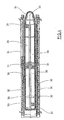
- FIG. 1 The basic structure of a device for forming preforms (1) in container (2) is shown in FIG. 1 and in FIG. 2.
- the device for forming the container (2) consists essentially of a blowing station (3), which is provided with a blow mold (4) into which a preform (1) can be inserted.
- the preform (1) may be an injection-molded part of polyethylene terephthalate.
- the blow mold (4) consists of mold halves (5, 6) and a bottom part (7), which is a lifting device (8) is positionable.
- the preform (1) can be held in the region of the blowing station (3) by a transport mandrel (9) which, together with the preform (1), passes through a plurality of treatment stations within the device. But it is also possible to use the preform (1), for example via pliers or other handling means directly into the blow mold (4).
- a connecting piston (10) is arranged, which feeds the preform (1) compressed air and at the same time makes a seal relative to the transport mandrel (9).
- a connecting piston (10) is arranged, which feeds the preform (1) compressed air and at the same time makes a seal relative to the transport mandrel (9).
- a stretching of the preform (1) takes place in this embodiment by means of a stretching rod (11), which is positioned by a cylinder (12).
- a mechanical positioning of the stretch rod (11) is performed via curve segments which are acted upon by Abgriff rollers. The use of curve segments is particularly useful when a plurality of blowing stations (3) are arranged on a rotating blowing wheel
- the stretching system is designed such that a tandem arrangement of two cylinders (12) is provided. From a primary cylinder (13), the stretch rod (11) is first moved to the area of a bottom (14) of the preform (1) before the beginning of the actual stretching operation.
- the primary cylinder (13) with extended stretching rod together with a carriage (15) carrying the primary cylinder (13) is positioned by a secondary cylinder (16) or via a cam control.
- the secondary cylinder (16) in such a cam-controlled manner that a current stretching position is predetermined by a guide roller (17) which slides along a curved path during the execution of the stretching operation.
- the guide roller (17) is pressed by the secondary cylinder (16) against the guideway.
- the carriage (15) slides along two guide elements (18).
- the carriers (19, 20) are locked relative to one another by means of a locking device (20).
- Fig. 2 shows in addition to the blown container (2) and dashed lines drawn the preform (1) and schematically a developing container bladder (23).
- Fig. 3 shows the basic structure of a blow molding machine, which is provided with a heating section (24) and a rotating blowing wheel (25).
- a preform input (26) the preforms (1) are transported by transfer wheels (27, 28, 29) into the region of the heating path (24).
- Heater (30) and fan (31) are arranged along the heating path (24) in order to temper the preforms (1).
- After a sufficient temperature control of the preforms (1) they are transferred to the blowing wheel (25), in the region of which the blowing stations (3) are arranged.
- the finished blown containers (2) are fed by further transfer wheels to a delivery line (32).
- thermoplastic material different plastics can be used.
- PET, PEN or PP can be used.
- the expansion of the preform (1) during the orientation process is carried out by compressed air supply.
- the compressed air supply is in a Vorblasphase, in the gas, For example, compressed air is supplied at a low pressure level and subdivided into a subsequent main blowing phase in which gas at a higher pressure level is supplied.
- compressed air is typically used at a pressure in the interval of 10 bar to 25 bar and during the main blowing phase compressed air is supplied at a pressure in the interval of 25 bar to 40 bar.
- the heating section (24) from a plurality of revolving transport elements (33) is formed, which are strung together like a chain and guided by guide wheels (34).
- guide wheels (34) In particular, it is envisaged to open a substantially rectangular basic contour by the chain-like arrangement.
- a single relatively large-sized guide wheel (34) and in the region of adjacent deflections two comparatively smaller dimensioned guide wheels (36) used In principle, however, any other guides are conceivable.
- a larger amount of preforms (1) per unit time can be tempered by the larger number of radiant heaters (30).
- the fans (31) introduce cooling air into the region of cooling air ducts (39), which in each case oppose the associated radiant heaters (30) and emit the cooling air via outflow openings.
- a flow direction for the cooling air is realized substantially transversely to a transport direction of the preforms (1).
- the cooling air ducts (39) can provide reflectors for the heating radiation in the area opposite the radiant heaters (30), and it is likewise possible to realize cooling of the radiant heaters (30) via the discharged cooling air.
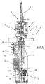
- FIG. 5 shows an illustration of the blowing station (3) modified from the representation in FIG. 1 in a viewing direction from the front.
- the stretch rod (11) is supported by a stretch rod carrier (41) which is formed from a carrier base (40) and a roller carrier (43) connected to the carrier base (40) via a coupling element (42) ,
- the roller carrier (43) holds the guide roller (17), which serves to position the stretching system.
- the guide roller (17) is guided along a curved path, not shown. It is here a complete mechanical Control of the stretching process realized.
- the coupling element (42) illustrated in Fig. 5 can also be used in the embodiment according to Fig. 1 for enabling a complete mechanical decoupling of the cylinders (12) from each other or from a support element for the guide roller (17).
- Fig. 5 illustrates a locked state of the coupling element (42) in which the support base (40) and the roller carrier (43) are interconnected by the coupling element (42).
- a rigid mechanical coupling which leads to a positioning of the guide roller (17) being directly and directly converted into a positioning of the stretch rod (11).
- an exactly predetermined positioning of the stretching rod (11) is present and the positioning of the stretching rod (11) is effected at a plurality of blowing stations (3) arranged on the blowing wheel (25) at each blowing station (3 ) exactly reproduced.
- This exact mechanical specification of the positioning of the stretch rod (11) contributes to a high product quality and to a high uniformity of the container (2) produced.
- Fig. 5 also shows the arrangement of a pneumatic block (46) for Blastikmakers the blow station (3).
- the pneumatic block (46) is equipped with high-pressure valves (47), which can be connected via connections (48) to one or more pressure supplies. After a blow-molding of the container (2) blown air to be discharged into an environment is first supplied to a silencer (49) via the pneumatic block (46).
- a typical implementation of the blowing process is the easiest be illustrated with reference to FIG. 2.
- After inserting the preform (1) in the blow mold (4) and a locking of the blowing station (3) is first a retraction of the stretching rod (11) in the preform (1) with simultaneous blowing pressure support such that the preform (1) through the axial stretching does not shrink radially onto the stretching rod (11).
Landscapes
- Engineering & Computer Science (AREA)
- Manufacturing & Machinery (AREA)
- Mechanical Engineering (AREA)
- Blow-Moulding Or Thermoforming Of Plastics Or The Like (AREA)
- Moulds For Moulding Plastics Or The Like (AREA)
Claims (16)
- Procédé pour le soufflage de récipients (2), dans lequel une préforme en matière thermoplastique est étirée par une barre d'étirage (11) après un conditionnement thermique à l'intérieur d'un moule de soufflage (4), et est transformée en un récipient (2) sous l'effet de la pression de soufflage, caractérisé en ce que l'amenée d'un gaz de soufflage sous pression dans le récipient (2), agencé dans le moule de soufflage (4), est activée avant que la barre d'étirage (11) ait effectué une partie importante de son parcours de retrait hors du récipient (2), et en ce que, après l'arrêt de l'amenée de gaz de soufflage, est seulement générée une faible réduction de la pression de soufflage, dont l'importance est déterminée par l'augmentation de volume à l'intérieur du récipient (2), à la suite du retrait de la partie de la barre d'étirage (11) qui est introduite dans le récipient (2).
- Procédé selon la revendication 1, caractérisé en ce que l'alimentation en gaz de soufflage est arrêtée avant le début du retrait de la barre d'étirage (11).
- Procédé selon revendication 1 ou 2, caractérisé en ce que, avant le retrait de la barre d'étirage (11), une pression de soufflage dans une plage de 30 bars à 50 bars, est générée dans le moule.
- Procédé selon l'une des revendications 1. à 3, caractérisé en ce que le mouvement de la barre d'étirage (11) est commandé, au moins partiellement, de manière mécanique.
- Procédé selon l'une des revendications 1 à 4, caractérisé en ce que chaque positionnement de la barre d'étirage (11) est commandé par un organe de commande courbe en utilisant une courbe d'étirage.
- procédé selon l'une des revendications 1 à 3, caractérisé en ce qu'un mouvement de la barre d'étirage (11) est commandé, au moins partiellement, de manière pneumatique.
- Procédé selon l'une des revendications 1 à 3, caractérisé en ce qu'un mouvement de la barre d'étirage (11) est commandé, au moins partiellement, de manière électrique.
- Procédé selon l'une des revendications 1 à 7, caractérisé en ce que l'alimentation en gaz de soufflage du moule de soufflage (4) est commandée par au moins une soupape.
- Procédé selon la revendication 8, caractérisé en ce que la soupape est commandée électriquement.
- Procédé pour le soufflage de récipients (2) en matériau thermoplastique, qui comprend au moins un poste de soufflage (3) pourvu d'un moule de soufflage (4), et qui est pourvu d'un dispositif d'étirage, dans le domaine duquel est agencée une barre d'étirage (11), à l'action de laquelle est soumise la préforme (1) qui est placée dans le moule de soufflage (4), et dans lequel la barre d'étirage (11) est couplée à une commande de déplacement pour la réalisation d'une coordination du mouvement de la barre d'étirage (11), et dans lequel le poste de soufflage (3) est raccordé à une alimentation en gaz de soufflage pourvu d'une commande de gaz de soufflage, caractérisé en ce que la commande de déplacement est couplée avec la commande de gaz de soufflage de telle manière qu'une commande de déroulement de processus est réalisée, laquelle arrête d'abord une amenée de gaz de soufflage dans le récipient et exécute ensuite au moins une partie essentielle du retrait de la barre d'étirage, et en ce qu'une faible réduction de pression à l'intérieur du récipient, laquelle est déterminée par le retrait de la barre d'étirage, est définie par une augmentation de volume, qui, pour sa part, est définie par le volume de la partie de la barre d'étirage introduit dans le récipient.
- Dispositif selon la revendication 10, caractérisé en ce que la barre d'étirage (11) est couplée avec une commande en courbe.
- Dispositif selon la revendication 10, caractérisé en ce que la barre d'étirage (11) est couplée avec une commande pneumatique.
- Dispositif selon la revendication 10, caractérisé en ce que la barre d'étirage est couplée avec une commande électrique.
- Dispositif selon l'une des revendications 10 à 13, caractérisé en ce que la conduite d'alimentation en gaz de soufflage présente une commande à soupape.
- Dispositif selon l'une des revendications 10 à 14 caractérisé en ce que la conduite d'alimentation en gaz de soufflage présente au moins une soupape à commande électrique.
- Dispositif selon l'une des revendications 10 à 15, caractérisé en ce que le poste de soufflage (3) est agencé sur une tourelle de soufflage rotative (25).
Applications Claiming Priority (2)
| Application Number | Priority Date | Filing Date | Title |
|---|---|---|---|
| DE102004012124 | 2004-03-12 | ||
| DE102004012124A DE102004012124A1 (de) | 2004-03-12 | 2004-03-12 | Verfahren und Vorrichtung zur Blasformung von Behältern |
Publications (2)
| Publication Number | Publication Date |
|---|---|
| EP1574318A1 EP1574318A1 (fr) | 2005-09-14 |
| EP1574318B1 true EP1574318B1 (fr) | 2007-04-11 |
Family
ID=34813678
Family Applications (1)
| Application Number | Title | Priority Date | Filing Date |
|---|---|---|---|
| EP05000443A Active EP1574318B1 (fr) | 2004-03-12 | 2005-01-12 | Procédé et appareil de formage de récipients par soufflage |
Country Status (3)
| Country | Link |
|---|---|
| EP (1) | EP1574318B1 (fr) |
| AT (1) | ATE359166T1 (fr) |
| DE (2) | DE102004012124A1 (fr) |
Families Citing this family (6)
| Publication number | Priority date | Publication date | Assignee | Title |
|---|---|---|---|---|
| DE102005040905A1 (de) * | 2005-04-12 | 2006-10-19 | Sig Technology Ltd. | Verfahren und Vorrichtung zur Positionierung eines Bauelementes |
| DE102005045942A1 (de) * | 2005-09-26 | 2007-04-12 | Sig Technology Ltd. | Verfahren und Vorrichtung zur Blasformung von Behältern |
| DE102009031681A1 (de) | 2009-07-03 | 2011-01-05 | Krones Ag | Blasmaschine und Verfahren zum Herstellen von Hohlkörpern |
| DE102011076062A1 (de) * | 2011-05-18 | 2012-11-22 | Krones Aktiengesellschaft | Hydraulisches Recken |
| DE102013103543A1 (de) * | 2013-04-09 | 2014-10-09 | Krones Ag | Vorrichtung und Verfahren zum Umformen von Kunststoffvorformlingen zu Kunststoffbehältnissen |
| JP6680685B2 (ja) * | 2014-03-10 | 2020-04-15 | ディスクマ アクチェンゲゼルシャフト | 容器内にヘッドスペースを形成し、設定する方法 |
Family Cites Families (4)
| Publication number | Priority date | Publication date | Assignee | Title |
|---|---|---|---|---|
| BR7601582A (pt) * | 1975-03-17 | 1976-09-14 | Monsanto Co | Aparelho aperfeicoado para formar continuamente artigos molecularmente orientados |
| US4372910A (en) * | 1980-06-23 | 1983-02-08 | Van Dorn Company | Method for molding hollow plastic articles |
| EP0499136A3 (en) * | 1991-02-14 | 1993-06-23 | Husky Injection Molding Systems Ltd. | Servo electric driven stretch rods for blow molding machine |
| US6186760B1 (en) * | 1997-08-01 | 2001-02-13 | Greig S. Latham | Blow mold machine monitor and control system |
-
2004
- 2004-03-12 DE DE102004012124A patent/DE102004012124A1/de not_active Withdrawn
-
2005
- 2005-01-12 DE DE502005000567T patent/DE502005000567D1/de active Active
- 2005-01-12 EP EP05000443A patent/EP1574318B1/fr active Active
- 2005-01-12 AT AT05000443T patent/ATE359166T1/de active
Non-Patent Citations (1)
| Title |
|---|
| None * |
Also Published As
| Publication number | Publication date |
|---|---|
| ATE359166T1 (de) | 2007-05-15 |
| DE102004012124A1 (de) | 2005-10-06 |
| EP1574318A1 (fr) | 2005-09-14 |
| DE502005000567D1 (de) | 2007-05-24 |
Similar Documents
| Publication | Publication Date | Title |
|---|---|---|
| EP2144742B1 (fr) | Dispositif de moulage par soufflage de récipients | |
| EP1789248B1 (fr) | Procede et dispositif de soufflage de contenants | |
| EP2040905B1 (fr) | Procédé et dispositif de moulage de récipients par soufflage | |
| EP1868767B1 (fr) | Procede et dispositif de positionnement d'un composant | |
| EP1910056B1 (fr) | Procede et dispositif de positionnement d'un composant | |
| WO2007110018A1 (fr) | PROCEDE ET DISPOSITIF DE FORMAge-SOUFFLAGE DE RECIPIENTS PAR RECOURS A LA MESURE DE L'EPAISSEUR DE PAROIS DE L'OBJET FACONNE | |
| EP2429795A1 (fr) | Procédé et dispositif pour le moulage par soufflage et le remplissage de récipients | |
| EP1574318B1 (fr) | Procédé et appareil de formage de récipients par soufflage | |
| DE112006000800B4 (de) | Verfahren und Vorrichtung zur Blasformung von Behältern unter Verwendung eines beweglich geführten Ventilträgers | |
| WO2011091780A2 (fr) | Procédé et dispositif de moulage par soufflage de récipients | |
| WO2009124539A1 (fr) | Procédé et dispositif de moulage par soufflage de récipients | |
| WO2013107657A1 (fr) | Procédé et dispositif de moulage de contenants par soufflage | |
| EP1732743B1 (fr) | Procede et dispositif de moulage de contenants par soufflage, faisant appel a une vitesse d'augmentation de pression reduite | |
| EP2544875B1 (fr) | Procédé et dispositif pour le moulage par soufflage de contenants | |
| EP1566258A2 (fr) | Appareil pour l'usinage de pièces | |
| EP2694270B1 (fr) | Dispositif pour le moulage de recipients par soufflage | |
| EP2054214B1 (fr) | Procédé et dispositif de formation de récipients par soufflage | |
| WO2007033631A2 (fr) | Procede et dispositif pour le moulage par soufflage de contenants | |
| EP1660302B1 (fr) | Procede et dispositif de moulage par soufflage de pieces a l'aide d'une broche d'etirage par soufflage pourvue d'orifices d'amenee d'air speciaux | |
| EP1473139B1 (fr) | Procédé et appareil de formage de récipients par soufflage | |
| EP2044334B1 (fr) | Procede et dispositif de formage de recipients par soufflage | |
| EP2129508B1 (fr) | Procédé de moulage par soufflage de contenants |
Legal Events
| Date | Code | Title | Description |
|---|---|---|---|
| PUAI | Public reference made under article 153(3) epc to a published international application that has entered the european phase |
Free format text: ORIGINAL CODE: 0009012 |
|
| AK | Designated contracting states |
Kind code of ref document: A1 Designated state(s): AT BE BG CH CY CZ DE DK EE ES FI FR GB GR HU IE IS IT LI LT LU MC NL PL PT RO SE SI SK TR |
|
| AX | Request for extension of the european patent |
Extension state: AL BA HR LV MK YU |
|
| 17P | Request for examination filed |
Effective date: 20051012 |
|
| AKX | Designation fees paid |
Designated state(s): AT BE BG CH CY CZ DE DK EE ES FI FR GB GR HU IE IS IT LI LT LU MC NL PL PT RO SE SI SK TR |
|
| GRAP | Despatch of communication of intention to grant a patent |
Free format text: ORIGINAL CODE: EPIDOSNIGR1 |
|
| GRAS | Grant fee paid |
Free format text: ORIGINAL CODE: EPIDOSNIGR3 |
|
| GRAA | (expected) grant |
Free format text: ORIGINAL CODE: 0009210 |
|
| AK | Designated contracting states |
Kind code of ref document: B1 Designated state(s): AT BE BG CH CY CZ DE DK EE ES FI FR GB GR HU IE IS IT LI LT LU MC NL PL PT RO SE SI SK TR |
|
| PG25 | Lapsed in a contracting state [announced via postgrant information from national office to epo] |
Ref country code: SI Free format text: LAPSE BECAUSE OF FAILURE TO SUBMIT A TRANSLATION OF THE DESCRIPTION OR TO PAY THE FEE WITHIN THE PRESCRIBED TIME-LIMIT Effective date: 20070411 Ref country code: FI Free format text: LAPSE BECAUSE OF FAILURE TO SUBMIT A TRANSLATION OF THE DESCRIPTION OR TO PAY THE FEE WITHIN THE PRESCRIBED TIME-LIMIT Effective date: 20070411 |
|
| REG | Reference to a national code |
Ref country code: GB Ref legal event code: FG4D Free format text: NOT ENGLISH |
|
| REG | Reference to a national code |
Ref country code: CH Ref legal event code: EP |
|
| REG | Reference to a national code |
Ref country code: IE Ref legal event code: FG4D Free format text: LANGUAGE OF EP DOCUMENT: GERMAN |
|
| REF | Corresponds to: |
Ref document number: 502005000567 Country of ref document: DE Date of ref document: 20070524 Kind code of ref document: P |
|
| PG25 | Lapsed in a contracting state [announced via postgrant information from national office to epo] |
Ref country code: SE Free format text: LAPSE BECAUSE OF FAILURE TO SUBMIT A TRANSLATION OF THE DESCRIPTION OR TO PAY THE FEE WITHIN THE PRESCRIBED TIME-LIMIT Effective date: 20070711 |
|
| PG25 | Lapsed in a contracting state [announced via postgrant information from national office to epo] |
Ref country code: ES Free format text: LAPSE BECAUSE OF FAILURE TO SUBMIT A TRANSLATION OF THE DESCRIPTION OR TO PAY THE FEE WITHIN THE PRESCRIBED TIME-LIMIT Effective date: 20070722 |
|
| PG25 | Lapsed in a contracting state [announced via postgrant information from national office to epo] |
Ref country code: IS Free format text: LAPSE BECAUSE OF FAILURE TO SUBMIT A TRANSLATION OF THE DESCRIPTION OR TO PAY THE FEE WITHIN THE PRESCRIBED TIME-LIMIT Effective date: 20070811 |
|
| PG25 | Lapsed in a contracting state [announced via postgrant information from national office to epo] |
Ref country code: PT Free format text: LAPSE BECAUSE OF FAILURE TO SUBMIT A TRANSLATION OF THE DESCRIPTION OR TO PAY THE FEE WITHIN THE PRESCRIBED TIME-LIMIT Effective date: 20070911 |
|
| NLV1 | Nl: lapsed or annulled due to failure to fulfill the requirements of art. 29p and 29m of the patents act | ||
| GBV | Gb: ep patent (uk) treated as always having been void in accordance with gb section 77(7)/1977 [no translation filed] |
Effective date: 20070411 |
|
| PG25 | Lapsed in a contracting state [announced via postgrant information from national office to epo] |
Ref country code: PL Free format text: LAPSE BECAUSE OF FAILURE TO SUBMIT A TRANSLATION OF THE DESCRIPTION OR TO PAY THE FEE WITHIN THE PRESCRIBED TIME-LIMIT Effective date: 20070411 |
|
| REG | Reference to a national code |
Ref country code: IE Ref legal event code: FD4D |
|
| ET | Fr: translation filed | ||
| PG25 | Lapsed in a contracting state [announced via postgrant information from national office to epo] |
Ref country code: IE Free format text: LAPSE BECAUSE OF FAILURE TO SUBMIT A TRANSLATION OF THE DESCRIPTION OR TO PAY THE FEE WITHIN THE PRESCRIBED TIME-LIMIT Effective date: 20070411 Ref country code: CZ Free format text: LAPSE BECAUSE OF FAILURE TO SUBMIT A TRANSLATION OF THE DESCRIPTION OR TO PAY THE FEE WITHIN THE PRESCRIBED TIME-LIMIT Effective date: 20070411 Ref country code: DK Free format text: LAPSE BECAUSE OF FAILURE TO SUBMIT A TRANSLATION OF THE DESCRIPTION OR TO PAY THE FEE WITHIN THE PRESCRIBED TIME-LIMIT Effective date: 20070411 Ref country code: NL Free format text: LAPSE BECAUSE OF FAILURE TO SUBMIT A TRANSLATION OF THE DESCRIPTION OR TO PAY THE FEE WITHIN THE PRESCRIBED TIME-LIMIT Effective date: 20070411 Ref country code: BG Free format text: LAPSE BECAUSE OF FAILURE TO SUBMIT A TRANSLATION OF THE DESCRIPTION OR TO PAY THE FEE WITHIN THE PRESCRIBED TIME-LIMIT Effective date: 20070711 |
|
| PLBE | No opposition filed within time limit |
Free format text: ORIGINAL CODE: 0009261 |
|
| STAA | Information on the status of an ep patent application or granted ep patent |
Free format text: STATUS: NO OPPOSITION FILED WITHIN TIME LIMIT |
|
| PG25 | Lapsed in a contracting state [announced via postgrant information from national office to epo] |
Ref country code: LT Free format text: LAPSE BECAUSE OF FAILURE TO SUBMIT A TRANSLATION OF THE DESCRIPTION OR TO PAY THE FEE WITHIN THE PRESCRIBED TIME-LIMIT Effective date: 20070411 Ref country code: SK Free format text: LAPSE BECAUSE OF FAILURE TO SUBMIT A TRANSLATION OF THE DESCRIPTION OR TO PAY THE FEE WITHIN THE PRESCRIBED TIME-LIMIT Effective date: 20070411 |
|
| 26N | No opposition filed |
Effective date: 20080114 |
|
| PG25 | Lapsed in a contracting state [announced via postgrant information from national office to epo] |
Ref country code: GR Free format text: LAPSE BECAUSE OF FAILURE TO SUBMIT A TRANSLATION OF THE DESCRIPTION OR TO PAY THE FEE WITHIN THE PRESCRIBED TIME-LIMIT Effective date: 20070712 Ref country code: GB Free format text: LAPSE BECAUSE OF FAILURE TO SUBMIT A TRANSLATION OF THE DESCRIPTION OR TO PAY THE FEE WITHIN THE PRESCRIBED TIME-LIMIT Effective date: 20070411 |
|
| PG25 | Lapsed in a contracting state [announced via postgrant information from national office to epo] |
Ref country code: RO Free format text: LAPSE BECAUSE OF FAILURE TO SUBMIT A TRANSLATION OF THE DESCRIPTION OR TO PAY THE FEE WITHIN THE PRESCRIBED TIME-LIMIT Effective date: 20070411 |
|
| BERE | Be: lapsed |
Owner name: SIG TECHNOLOGY LTD. Effective date: 20080131 |
|
| PG25 | Lapsed in a contracting state [announced via postgrant information from national office to epo] |
Ref country code: MC Free format text: LAPSE BECAUSE OF NON-PAYMENT OF DUE FEES Effective date: 20080131 |
|
| PG25 | Lapsed in a contracting state [announced via postgrant information from national office to epo] |
Ref country code: EE Free format text: LAPSE BECAUSE OF FAILURE TO SUBMIT A TRANSLATION OF THE DESCRIPTION OR TO PAY THE FEE WITHIN THE PRESCRIBED TIME-LIMIT Effective date: 20070411 |
|
| PG25 | Lapsed in a contracting state [announced via postgrant information from national office to epo] |
Ref country code: BE Free format text: LAPSE BECAUSE OF NON-PAYMENT OF DUE FEES Effective date: 20080131 |
|
| PG25 | Lapsed in a contracting state [announced via postgrant information from national office to epo] |
Ref country code: CY Free format text: LAPSE BECAUSE OF FAILURE TO SUBMIT A TRANSLATION OF THE DESCRIPTION OR TO PAY THE FEE WITHIN THE PRESCRIBED TIME-LIMIT Effective date: 20070411 |
|
| REG | Reference to a national code |
Ref country code: CH Ref legal event code: PL |
|
| PG25 | Lapsed in a contracting state [announced via postgrant information from national office to epo] |
Ref country code: CH Free format text: LAPSE BECAUSE OF NON-PAYMENT OF DUE FEES Effective date: 20090131 Ref country code: LI Free format text: LAPSE BECAUSE OF NON-PAYMENT OF DUE FEES Effective date: 20090131 |
|
| REG | Reference to a national code |
Ref country code: FR Ref legal event code: TP |
|
| PG25 | Lapsed in a contracting state [announced via postgrant information from national office to epo] |
Ref country code: HU Free format text: LAPSE BECAUSE OF FAILURE TO SUBMIT A TRANSLATION OF THE DESCRIPTION OR TO PAY THE FEE WITHIN THE PRESCRIBED TIME-LIMIT Effective date: 20071012 Ref country code: LU Free format text: LAPSE BECAUSE OF NON-PAYMENT OF DUE FEES Effective date: 20080112 |
|
| PG25 | Lapsed in a contracting state [announced via postgrant information from national office to epo] |
Ref country code: TR Free format text: LAPSE BECAUSE OF FAILURE TO SUBMIT A TRANSLATION OF THE DESCRIPTION OR TO PAY THE FEE WITHIN THE PRESCRIBED TIME-LIMIT Effective date: 20070411 |
|
| REG | Reference to a national code |
Ref country code: DE Ref legal event code: R081 Ref document number: 502005000567 Country of ref document: DE Owner name: KHS CORPOPLAST GMBH, DE Free format text: FORMER OWNER: KHS CORPOPLAST GMBH & CO. KG, 20539 HAMBURG, DE Effective date: 20110504 |
|
| REG | Reference to a national code |
Ref country code: DE Ref legal event code: R082 Ref document number: 502005000567 Country of ref document: DE |
|
| REG | Reference to a national code |
Ref country code: FR Ref legal event code: PLFP Year of fee payment: 12 |
|
| REG | Reference to a national code |
Ref country code: FR Ref legal event code: PLFP Year of fee payment: 13 |
|
| REG | Reference to a national code |
Ref country code: FR Ref legal event code: PLFP Year of fee payment: 14 |
|
| REG | Reference to a national code |
Ref country code: DE Ref legal event code: R081 Ref document number: 502005000567 Country of ref document: DE Owner name: KHS GMBH, DE Free format text: FORMER OWNER: KHS CORPOPLAST GMBH, 22145 HAMBURG, DE |
|
| PGFP | Annual fee paid to national office [announced via postgrant information from national office to epo] |
Ref country code: FR Payment date: 20230124 Year of fee payment: 19 |
|
| PGFP | Annual fee paid to national office [announced via postgrant information from national office to epo] |
Ref country code: IT Payment date: 20230120 Year of fee payment: 19 |
|
| PGFP | Annual fee paid to national office [announced via postgrant information from national office to epo] |
Ref country code: AT Payment date: 20240122 Year of fee payment: 20 |
|
| PGFP | Annual fee paid to national office [announced via postgrant information from national office to epo] |
Ref country code: DE Payment date: 20240119 Year of fee payment: 20 |