EP1304498A1 - Support antivibratoire hydraulique - Google Patents
Support antivibratoire hydraulique Download PDFInfo
- Publication number
- EP1304498A1 EP1304498A1 EP02292499A EP02292499A EP1304498A1 EP 1304498 A1 EP1304498 A1 EP 1304498A1 EP 02292499 A EP02292499 A EP 02292499A EP 02292499 A EP02292499 A EP 02292499A EP 1304498 A1 EP1304498 A1 EP 1304498A1
- Authority
- EP
- European Patent Office
- Prior art keywords
- support
- grids
- elastomer
- antivibration
- pieces
- Prior art date
- Legal status (The legal status is an assumption and is not a legal conclusion. Google has not performed a legal analysis and makes no representation as to the accuracy of the status listed.)
- Granted
Links
- 229920001971 elastomer Polymers 0.000 claims abstract description 40
- 239000000806 elastomer Substances 0.000 claims abstract description 40
- 238000005192 partition Methods 0.000 claims abstract description 26
- 239000012528 membrane Substances 0.000 claims abstract description 13
- 238000013016 damping Methods 0.000 claims abstract description 3
- 239000002184 metal Substances 0.000 claims description 18
- 239000007788 liquid Substances 0.000 claims description 7
- 230000000295 complement effect Effects 0.000 claims description 3
- 239000012530 fluid Substances 0.000 abstract 1
- 208000031968 Cadaver Diseases 0.000 description 8
- 230000006835 compression Effects 0.000 description 3
- 238000007906 compression Methods 0.000 description 3
- 230000002787 reinforcement Effects 0.000 description 3
- 235000008612 Gnetum gnemon Nutrition 0.000 description 2
- 240000000018 Gnetum gnemon Species 0.000 description 2
- 229910001234 light alloy Inorganic materials 0.000 description 2
- 238000000465 moulding Methods 0.000 description 2
- 238000010009 beating Methods 0.000 description 1
- 239000000470 constituent Substances 0.000 description 1
- 238000002788 crimping Methods 0.000 description 1
- 238000006073 displacement reaction Methods 0.000 description 1
- 239000000463 material Substances 0.000 description 1
- 230000002093 peripheral effect Effects 0.000 description 1
- 238000011084 recovery Methods 0.000 description 1
Images



Classifications
-
- F—MECHANICAL ENGINEERING; LIGHTING; HEATING; WEAPONS; BLASTING
- F16—ENGINEERING ELEMENTS AND UNITS; GENERAL MEASURES FOR PRODUCING AND MAINTAINING EFFECTIVE FUNCTIONING OF MACHINES OR INSTALLATIONS; THERMAL INSULATION IN GENERAL
- F16F—SPRINGS; SHOCK-ABSORBERS; MEANS FOR DAMPING VIBRATION
- F16F13/00—Units comprising springs of the non-fluid type as well as vibration-dampers, shock-absorbers, or fluid springs
- F16F13/04—Units comprising springs of the non-fluid type as well as vibration-dampers, shock-absorbers, or fluid springs comprising both a plastics spring and a damper, e.g. a friction damper
- F16F13/06—Units comprising springs of the non-fluid type as well as vibration-dampers, shock-absorbers, or fluid springs comprising both a plastics spring and a damper, e.g. a friction damper the damper being a fluid damper, e.g. the plastics spring not forming a part of the wall of the fluid chamber of the damper
- F16F13/08—Units comprising springs of the non-fluid type as well as vibration-dampers, shock-absorbers, or fluid springs comprising both a plastics spring and a damper, e.g. a friction damper the damper being a fluid damper, e.g. the plastics spring not forming a part of the wall of the fluid chamber of the damper the plastics spring forming at least a part of the wall of the fluid chamber of the damper
- F16F13/10—Units comprising springs of the non-fluid type as well as vibration-dampers, shock-absorbers, or fluid springs comprising both a plastics spring and a damper, e.g. a friction damper the damper being a fluid damper, e.g. the plastics spring not forming a part of the wall of the fluid chamber of the damper the plastics spring forming at least a part of the wall of the fluid chamber of the damper the wall being at least in part formed by a flexible membrane or the like
- F16F13/105—Units comprising springs of the non-fluid type as well as vibration-dampers, shock-absorbers, or fluid springs comprising both a plastics spring and a damper, e.g. a friction damper the damper being a fluid damper, e.g. the plastics spring not forming a part of the wall of the fluid chamber of the damper the plastics spring forming at least a part of the wall of the fluid chamber of the damper the wall being at least in part formed by a flexible membrane or the like characterised by features of partitions between two working chambers
- F16F13/106—Design of constituent elastomeric parts, e.g. decoupling valve elements, or of immediate abutments therefor, e.g. cages
Definitions
- the present invention relates to supports hydraulic vibration dampers.
- Document FR-A-2 714 947 describes an example of a such antivibration support, which gives all satisfaction.
- the object of the present invention is in particular to further improve such antivibration mounts to reduce any possible clicking noises appear due to the beating of the flexible membrane of the decoupling valve between the two grids of this valve, especially when the anti-vibration support is used to mount a vehicle powertrain on the body of this vehicle.
- a support antivibration of the kind in question is characterized in that that the first and second grids are connected by elastic connections respectively to the first and second support parts (the elastic links in question possibly being made up of two zones of the same elastic piece).
- the beats are damped of the diaphragm of the decoupling valve against the grids of this valve due to the flexibility of said connections elastic, which limits or even eliminates clicking noises due to the decoupling valve.
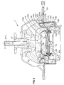
- Figure 1 shows an anti-vibration support hydraulic intended to connect for example a group vehicle powertrain at the body of this vehicle.
- the working and compensation chambers A, B are connected to each other permanently by a passage constricted C delimited inside the rigid partition 5 and extending angularly at the periphery exterior of this partition.
- strangled passage C could extend on one floor and be delimited for example only by two parts forming the rigid partition 5.
- the rigid partition 5 further comprises a decoupling valve 15 which includes a membrane of elastomer 16 mounted with a small clearance (for example of of the order of 0.5 mm) between two grids 17, 18 which make communicate the two faces of the membrane 16 respectively with working chamber A and with working chamber compensation B.
- a decoupling valve 15 which includes a membrane of elastomer 16 mounted with a small clearance (for example of of the order of 0.5 mm) between two grids 17, 18 which make communicate the two faces of the membrane 16 respectively with working chamber A and with working chamber compensation B.
- the grids 17, 18 can be produced by example of a rigid material, in particular metal.
- the grid 17 belongs to the upper part 6 of the rigid partition and is connected elastically to the ring 7, advantageously by an elastomer ring 19 which is interposed radially between the grid 17 and the crown 7 and which is molded and bonded on these two parts.
- the grid 18 belongs to the lower part 11 of the rigid partition and is connected elastically to the crown 12, preferably by a ring 20 of elastomer which is interposed radially between the grid 18 and the crown 12 and which is overmolded and adhered to these two parts.
- the rings 19, 20 made of elastomer have a stiffness between 100 N / mm and 200 N / mm along the Z axis.
- the membrane 16 vibrates between the grids 17, 18 by absorbing the vibration.
- the support hydraulic vibration damper also includes, as previously, first and second frames rigid metal 101, 102 connected together by a elastomer body 103.
- the first frame 101 can be a base upper intended to be connected for example to the group vehicle powertrain, in particular by means of a stud 101a.
- the second frame 102 meanwhile, has an annular shape centered on a vertical axis Z and is intended to be fixed for example to the vehicle body.
- the second frame 102 includes two pieces of sheet metal 102a, 102b.
- the sheet metal part 102a may include a part stamped inner 102c which forms an annular groove 102d open down.
- the sheet metal part 102b includes a side wall 102e, which may for example be cylindrical and centered on the Z axis, this side wall extending downwards up to an inner annular bearing edge 102f.
- the elastomer body 103 can have example a bell shape extending along the Z axis between on the one hand, a summit 103a molded and adhered to the first frame 101 and on the other hand, an annular base 103b overmolded and bonded on the inside stamped 102c of the sheet metal part 102a.
- the body wall in elastomer 103 is thick enough to withstand vertical compression forces due to weight recovery of the vehicle thruster block.
- the anti-vibration support includes also a thin and flexible wall 104 made of elastomer, which may in particular be in the form of a bellows and the periphery of which is tightly connected to the second reinforcement 102.
- the periphery of the flexible wall 104 is overmolded and adhered to the edge internal annular support 102f.
- the flexible wall 104 defines, with the second armature 102 and the elastomer body 103, a housing closed and filled with liquid, which is separated in two by a rigid central partition 105 extending substantially perpendicular to the Z axis.
- a working chamber A filled with liquid is thus delimited between the partition 105 and the body in elastomer 103, while a clearing house D easily deformable, also filled with liquid, is delimited between the partition 105 and the flexible wall 104.
- these working chambers A, B can advantageously be linked together so permanent by a constricted passage C which is delimited at at least partially by the rigid partition 5 and which extends angularly at the outer periphery of this partition.
- the partition 105 includes a first support piece 107 made of sheet metal cut and stamped (see also Figures 4 and 5).
- This first support piece has a part planar annular 107a which is extended externally by an annular edge raised 107d and internally by a stamped part 107c.
- the stamped part 107c has a crenellated inner annular edge 107d comprising a plurality of slots or protruding teeth radially inward.
- the raised edge 107b of the first support piece 107 is fitted substantially without play in the wall side 102e mentioned above (see Figure 3), and presents an upper free end in tight contact against a layer of elastomer overmolded on the underside of the sheet metal part 102a.
- the base 103a of the elastomer body and the stamped part 102c of the sheet metal part 102a are supported waterproof against the flat annular part 107a of the first support piece 107.
- annular deflector 106 in sheet metal can possibly be interposed between the base of the elastomer body and the annular part 107a of the first support piece, this annular deflector having a frustoconical part which extends in the working chamber A while converging upwards.
- the rigid partition 105 further comprises a second support piece 112 made of cut and stamped sheet metal, this second support piece may include a planar annular part 112a which is extended towards outside and down by an axial jump 112d itself extended radially outward by an edge support ring 112c.
- the planar annular part 112a is further extended inward by a portion stamped interior 112d which has an interior edge serrated 112d with a plurality of slots or teeth 112f projecting radially inward.
- the full annular part 112a of the second support part is in tight contact against the part annular 107a of the first support piece, and the edge external support 112c of said second support part is sealingly pressed against the internal bearing edge 102f above.
- the first support piece 107 delimits with the aforementioned throat 102d, a first stage C1 of the strangled passage C, this first stage communicating with the working chamber A through an opening 109 made in the stamped inner part 102c.
- a second stage C2 of the constricted passage C is by elsewhere delimited between on the one hand, the first and second support pieces 107, 112, and secondly, the side wall 102e belonging to the sheet metal part 102b.
- This second stage C2 communicates with the first stage C1 by a recess 107f made in the first support piece 107, and with the clearing house B by a recess 112g in the second support piece 112 (see figure 5).
- first and second support pieces 107, 112 define between them a housing in which is disposed a valve decoupling 115 which performs the same function as in the first embodiment and which comprises a membrane flexible 116 made of elastomer mounted with low axial clearance between two grids 117, 118 in sheet metal.
- the first grid 117 is stamped, while the second grid 118 is flat, but these two grids could if necessary be identical in shape.
- the first and second grids 117, 118 are stacked on top of each other, and two elastic links in elastomer, constituted for example by two rings in elastomer 119, 120 are interposed respectively between each grid 117, 118 and the support piece corresponding 107, 112.
- the rings elastomer 119, 120 could be made in one piece which would then be engaged around the periphery of grids 117, 118.
- the anti-vibration support according to the invention would always include two bonds elastics respectively connecting each grid 117, 118 to the corresponding support piece 107, 112, but these elastic bonds would consist of two zones in one piece.
- the first and second grids 117, 118 have preferably each a crenellated outer periphery, respectively 117a, 118a which includes slots or teeth, respectively 117d, 118d, which protrude radially outward.
- crenellated peripheries 117a, 117b are of preference of complementary shape of the peripheries crenellated interior 107d, 112th of the first and second support pieces, so that the grids 117, 118 can be made by cutting from the same sheet metal sides as the support parts 107, 112.
- the slots 117d, 118d, 107e, 112f are arranged in mutual correspondence, so that pinching the elastomer rings 112, 120 between said slots does not generate too much shear force important of said elastomer rings.
- the elastomer rings 117, 118 could be overmolded and adhered one between the first support piece 107 respectively and the first grid 117, the other between the second room support 112 and the second grid 118.
Landscapes
- Engineering & Computer Science (AREA)
- General Engineering & Computer Science (AREA)
- Mechanical Engineering (AREA)
- Combined Devices Of Dampers And Springs (AREA)
- Arrangement Or Mounting Of Propulsion Units For Vehicles (AREA)
Abstract
Description
- des première et deuxième armatures rigides destinées à être fixées aux deux éléments rigides à réunir,
- un corps en élastomère reliant entre elles les première et deuxième armatures,
- une chambre de travail remplie de liquide, partiellement délimitée par le corps en élastomère,
- au moins une chambre de compensation aisément déformable,
- et un clapet de découplage qui comporte une membrane souple déplaçable avec jeu entre des première et deuxième grilles rigides qui communiquent respectivement avec la chambre travail et avec la chambre de compensation, les première et deuxième grilles étant portées respectivement par des première et deuxième pièces de support rigides fixées à la deuxième armature.
- lesdites liaisons élastiques sont des liaisons en élastomère ;
- lesdites liaisons élastiques présentent une raideur comprise entre 100 N/mm et 200 N/mm selon un axe perpendiculaire aux première et deuxième grilles ;
- les première et deuxième pièces de support et les première et deuxième grilles forment ensemble une cloison qui sépare la chambre de travail et la chambre de compensation ;
- les première et deuxième pièces de support sont annulaires et entourent respectivement les première et deuxième grilles, lesdites première et deuxième grilles étant reliées respectivement aux première et deuxième pièces de support par des première et deuxième bagues d'élastomère qui constituent lesdites liaisons élastiques ;
- les première et deuxième pièces de support délimitent un passage étranglé qui fait communiquer en permanence la chambre de travail avec la chambre de compensation ;
- les première et deuxième bagues d'élastomère sont surmoulées et adhérisées respectivement sur les première et deuxième grilles et sur les première et deuxième pièces de support ;
- les première et deuxième grilles et les première et deuxième pièces de support sont des pièces de tôle découpées qui appartiennent à une cloison séparant la chambre de travail et la chambre de compensation, les première et deuxième pièces de support délimitant au moins partiellement un passage étranglé qui fait communiquer en permanence la chambre de travail avec la chambre de compensation ;
- les première et deuxième grilles comportent chacune une périphérie extérieure crénelée tandis que les première et deuxième pièces de support présentent chacune un périphérie intérieure crénelée, la périphérie intérieure crénelée de chaque pièce de support étant sensiblement complémentaire de la périphérie extérieure d'une des grilles ;
- la périphérie extérieure de chacune des première et deuxième grilles forme des créneaux faisant saillie radialement vers l'extérieur et la périphérie intérieure de chacune des première et deuxième pièces de support forme des créneaux faisant saillie radialement vers l'intérieur, les créneaux des première et deuxième grilles étant disposés sensiblement en correspondance mutuelle avec les créneaux des première et deuxième pièces de support.
- la figure 1 est une vue en coupe axiale d'un support antivibratoire selon une première forme de réalisation de l'invention,
- la figure 2 est une vue de détail de la cloison rigide qui sépare les deux chambres hydrauliques du support antivibratoires de la figure 1,
- la figure 3 est une vue en coupe axiale d'un support antivibratoire selon une deuxième forme de réalisation de l'invention,
- la figure 4 est une vue éclatée des différentes pièces constituant la cloïson centrale du support antivibratoire de la figure 1,
- la figure 5 est une vue en perspective de la cloison centrale du support antivibratoire de la figure 1, sans la membrane de son clapet de découplage,
- et les figures 6 et 7 sont des vues en plan des grilles appartenant à la cloison centrale des figures 4 et 5.
- une première armature métallique rigide 1, qui dans l'exemple représenté a la forme d'une embase destinée à supporter par exemple le groupe motopropulseur du véhicule, notamment au moyen d'un goujon 1a,
- une deuxième armature métallique rigide 2, qui dans l'exemple représenté a une forme annulaire centrée sur l'axe vertical Z du goujon 1a, cette deuxième armature étant destinée à être fixée par exemple à la caisse du véhicule,
- un corps en élastomère 3 en forme de cloche sensiblement tronconique qui relie entre elles les première et deuxième armatures 1, 2, le corps en élastomère s'étendant selon l'axe Z entre d'une part, un sommet 3a surmoulé et adhérisé sur la première armature 1 et d'autre part, une base annulaire 3b surmoulée et adhérisée sur la deuxième armature 2, la paroi du corps en élastomère 3 étant suffisamment épaisse pour résister aux efforts de compression verticaux dus à la reprise du poids du bloc motopropulseur,
- une paroi mince et souple 4 en élastomère, présentant par exemple une forme de soufflet et reliée de façon étanche à la deuxième armature 2 (notamment par sertissage de pattes 2a de la deuxième armature) de façon à délimiter avec le corps en élastomère 3 un volume étanche rempli de liquide,
- une cloison rigide 5 qui est solidarisée avec la deuxième armature 2 et qui est serrée entre la base 3b du corps en élastomère et les pattes rabattues 2a de la deuxième armature, la cloison rigide 5 s'étendant perpendiculairement à l'axe Z et séparant le volume intérieur du support antivibratoire entre d'une part, une chambre de travail A délimitée partiellement par le corps en élastomère et d'autre part, une chambre de compensation B aisément déformable et délimitée partiellement par la paroi mince 4 en élastomère.
- une pièce supérieure 6 comportant une couronne 7 qui est réalisée par exemple par moulage en alliage léger et qui délimite intérieurement une gorge 8 ouverte vers le bas, cette gorge communiquant avec la chambre de travail A par l'intermédiaire d'une ouverture 9,
- une rondelle intermédiaire de tôle 10 qui est plaquée sous la couronne 7 de façon à fermer la gorge 8 vers le bas en délimitant l'étage supérieur du passage étranglé C, cette rondelle 10 présentant une ouverture (non représentée) qui fait communiquer l'étage supérieur du passage étranglé C avec l'étage inférieur de ce passage,
- et une pièce inférieure 11 comportant une couronne annulaire périphérique 12 qui est réalisée par exemple par moulage en alliage léger et qui délimite intérieurement une gorge 13 ouverte vers le haut et fermée par la rondelle 10 susmentionnée, la gorge 13 délimitant l'étage inférieur du passage étranglé C et communiquant avec la chambre de compensation B par une ouverture 14.
Claims (10)
- Support antivibratoire hydraulique destiné à relier entre eux deux éléments rigides aux fins d'amortissement, ce support comportant au moins :caractérisé en ce que les première et deuxième grilles (17, 18 ; 117, 118) sont reliées par des liaisons élastiques (19, 20 ; 119, 120) respectivement aux première et deuxième pièces de support (7, 12 ; 107, 112).des première et deuxième armatures rigides (1, 2 ; 101, 102) destinées à être fixées aux deux éléments rigides à réunir,un corps en élastomère (3 ; 103) reliant entre elles les première et deuxième armatures (1, 2 ; 101, 102),une chambre de travail (A) remplie de liquide, partiellement délimitée par le corps en élastomère (3 ; 103),au moins une chambre de compensation (B) aisément déformable,et un clapet de découplage (15 ; 115) qui comporte une membrane souple (16 ; 116) déplaçable avec jeu entre des première et deuxième grilles (17, 18 ; 117, 118) rigides qui communiquent respectivement avec la chambre travail (A) et avec la chambre de compensation (B), les première et deuxième grilles étant portées respectivement par des première et deuxième pièces de support (7, 12 ; 107, 112) rigides fixées à la deuxième armature (2),
- Support antivibratoire selon la revendication 1 dans lequel lesdites liaisons élastiques (19, 20 ; 119, 120) sont des liaisons en élastomère.
- Support antivibratoire selon la revendication 1 ou la revendication 2, dans lequel lesdites liaisons élastiques (19, 20 ; 119, 120) présentent une raideur comprise entre 100 N/mm et 200 N/mm selon un axe (Z) perpendiculaire aux première et deuxième grilles (17, 18 ; 117, 118).
- Support antivibratoire selon l'une quelconque des revendications précédentes dans lequel les première et deuxième pièces de support (7, 12 ; 107, 112) et les première et deuxième grilles (17, 18 ; 117, 118) forment ensemble une cloison (5 ; 105) qui sépare la chambre de travail (A) et la chambre de compensation (B).
- Support antivibratoire selon la revendication 4, dans lequel les première et deuxième pièces de support (7, 12 ; 107, 112) sont annulaires et entourent respectivement les première et deuxième grilles (17, 18 ; 117, 118), lesdites première et deuxième grilles étant reliées respectivement aux première et deuxième pièces de support (7, 12 ; 107, 112) par des première et deuxième bagues d'élastomère (19, 20 ; 119, 120) qui constituent lesdites liaisons élastiques.
- Support antivibratoire selon la revendication 5, dans lequel les première et deuxième pièces de support (7, 12 ; 107, 112) délimitent un passage étranglé (C) qui fait communiquer en permanence la chambre de travail (A) avec la chambre de compensation (B).
- Support antivibratoire selon la revendication 5 ou la revendication 6, dans lequel les première et deuxième bagues d'élastomère (19, 20 ; 119, 120) sont surmoulées et adhérisées respectivement sur les première et deuxième grilles (17, 18 ; 117, 118) et sur les première et deuxième pièces de support (7, 12 ; 107, 112).
- Support antivibratoire selon l'une quelconque des revendications précédentes, dans lequel les première et deuxième grilles (117, 118) et les première et deuxième pièces de support (107, 112) sont des pièces de tôle découpées qui appartiennent à une cloison (105) séparant la chambre de travail (A) et la chambre de compensation (B), les première et deuxième pièces de support délimitant au moins partiellement un passage étranglé (C) qui fait communiquer en permanence la chambre de travail (A) avec la chambre de compensation (B).
- Support antivibratoire selon la revendication 8, dans lequel les première et deuxième grilles (117, 118) comportent chacune une périphérie extérieure crénelée (117a, 118a) tandis que les première et deuxième pièces de support (107, 112) présentent chacune un périphérie intérieure crénelée (107d, 112e), la périphérie intérieure crénelée (107d, 112e) de chaque pièce de support étant sensiblement complémentaire de la périphérie extérieure crénelée (117a, 118a) d'une des grilles.
- Support antivibratoire selon la revendication 9, dans lequel la périphérie extérieure de chacune des première et deuxième grilles forme des créneaux (117b, 118b) faisant saillie radialement vers l'extérieur et la périphérie intérieure de chacune des première et deuxième pièces de support forment des créneaux (107e, 112f) faisant saillie radialement vers l'intérieur, les créneaux des première et deuxième grilles étant disposés sensiblement en correspondance mutuelle avec les créneaux des première et deuxième pièces de support.
Applications Claiming Priority (2)
| Application Number | Priority Date | Filing Date | Title |
|---|---|---|---|
| FR0113437 | 2001-10-18 | ||
| FR0113437A FR2831236B1 (fr) | 2001-10-18 | 2001-10-18 | Support antivibratoire hydraulique |
Publications (2)
| Publication Number | Publication Date |
|---|---|
| EP1304498A1 true EP1304498A1 (fr) | 2003-04-23 |
| EP1304498B1 EP1304498B1 (fr) | 2005-08-03 |
Family
ID=8868432
Family Applications (1)
| Application Number | Title | Priority Date | Filing Date |
|---|---|---|---|
| EP02292499A Expired - Lifetime EP1304498B1 (fr) | 2001-10-18 | 2002-10-10 | Support antivibratoire hydraulique |
Country Status (7)
| Country | Link |
|---|---|
| US (1) | US6793206B2 (fr) |
| EP (1) | EP1304498B1 (fr) |
| JP (1) | JP4098059B2 (fr) |
| BR (1) | BR0204234A (fr) |
| DE (1) | DE60205323T2 (fr) |
| ES (1) | ES2244741T3 (fr) |
| FR (1) | FR2831236B1 (fr) |
Cited By (2)
| Publication number | Priority date | Publication date | Assignee | Title |
|---|---|---|---|---|
| EP2196344A1 (fr) * | 2008-12-15 | 2010-06-16 | Carl Freudenberg KG | Support hydraulique et cloison de découplage correspondante |
| CN102705426A (zh) * | 2012-06-12 | 2012-10-03 | 宁波拓普集团股份有限公司 | 一种新型液压悬置解耦结构 |
Families Citing this family (14)
| Publication number | Priority date | Publication date | Assignee | Title |
|---|---|---|---|---|
| DE10307680A1 (de) * | 2003-02-21 | 2004-09-30 | Carl Freudenberg Kg | Hydrolager |
| FR2856451B1 (fr) * | 2003-06-20 | 2006-09-01 | Hutchinson | Support antivibratoire hydraulique |
| FR2896842B1 (fr) * | 2006-02-01 | 2010-04-09 | Hutchinson | Support antivibratoire hydraulique et son procede de fabrication |
| DE102008054528A1 (de) * | 2008-12-11 | 2010-07-15 | Zf Friedrichshafen Ag | Axial dämpfendes Hydrolager |
| CN102720797A (zh) * | 2012-06-28 | 2012-10-10 | 宁波拓普集团股份有限公司 | 一种汽车发动机液压悬置流道组件 |
| DE102016116079A1 (de) * | 2016-08-29 | 2018-03-01 | Vibracoustic Gmbh | Hydrolager |
| US11959527B2 (en) | 2018-05-10 | 2024-04-16 | Prospira Corporation | Vibration isolator |
| US12196284B2 (en) | 2019-11-07 | 2025-01-14 | Prospira Corporation | Vibration-damping device |
| WO2021090886A1 (fr) | 2019-11-07 | 2021-05-14 | 株式会社ブリヂストン | Dispositif d'amortissement de vibrations |
| JP7350629B2 (ja) | 2019-11-07 | 2023-09-26 | 株式会社プロスパイラ | 防振装置 |
| CN114728573B (zh) | 2019-11-07 | 2025-11-04 | 株式会社普洛斯派 | 隔振装置 |
| US20220111540A1 (en) * | 2020-10-09 | 2022-04-14 | Nikon Corporation | Vibration reduction assembly with a gravity aligned reduction system |
| US12338871B2 (en) * | 2021-06-02 | 2025-06-24 | Vibracoustic Usa, Inc. | Hydraulic mount assembly and method |
| US11988264B2 (en) * | 2021-10-19 | 2024-05-21 | DRiV Automotive Inc. | Hydraulic damper with a baffle |
Citations (2)
| Publication number | Priority date | Publication date | Assignee | Title |
|---|---|---|---|---|
| FR2714947A1 (fr) | 1994-01-11 | 1995-07-13 | Hutchinson | Perfectionnements aux dispositifs antivibratoires hydrauliques. |
| EP0939243A2 (fr) * | 1998-02-25 | 1999-09-01 | Firma Carl Freudenberg | Support à amortissement hydraulique |
Family Cites Families (6)
| Publication number | Priority date | Publication date | Assignee | Title |
|---|---|---|---|---|
| US4721292A (en) * | 1986-07-24 | 1988-01-26 | Tokai Rubber Industries, Ltd. | Fluid-filled elastic mounting structure |
| JPH06100243B2 (ja) * | 1987-08-21 | 1994-12-12 | 東海ゴム工業株式会社 | 流体封入式マウント装置 |
| US4762309A (en) * | 1987-09-14 | 1988-08-09 | Saturn Corporation | Hydraulic mount having a flexible decoupler with an orifice therethrough |
| FR2632696B1 (fr) * | 1988-06-09 | 1993-10-01 | Hutchinson | Perfectionnements aux dispositifs antivibratoires hydrauliques |
| US5571263A (en) * | 1995-04-14 | 1996-11-05 | General Motors Corporation | Hydraulic engine mount with reduced impulse vibration |
| FR2828540B1 (fr) * | 2001-08-07 | 2003-10-31 | Hutchinson | Support antivibratoire hydraulique |
-
2001
- 2001-10-18 FR FR0113437A patent/FR2831236B1/fr not_active Expired - Fee Related
-
2002
- 2002-10-10 EP EP02292499A patent/EP1304498B1/fr not_active Expired - Lifetime
- 2002-10-10 ES ES02292499T patent/ES2244741T3/es not_active Expired - Lifetime
- 2002-10-10 DE DE60205323T patent/DE60205323T2/de not_active Expired - Lifetime
- 2002-10-18 US US10/273,902 patent/US6793206B2/en not_active Expired - Lifetime
- 2002-10-18 JP JP2002304569A patent/JP4098059B2/ja not_active Expired - Fee Related
- 2002-10-18 BR BR0204234-7A patent/BR0204234A/pt active Search and Examination
Patent Citations (2)
| Publication number | Priority date | Publication date | Assignee | Title |
|---|---|---|---|---|
| FR2714947A1 (fr) | 1994-01-11 | 1995-07-13 | Hutchinson | Perfectionnements aux dispositifs antivibratoires hydrauliques. |
| EP0939243A2 (fr) * | 1998-02-25 | 1999-09-01 | Firma Carl Freudenberg | Support à amortissement hydraulique |
Cited By (2)
| Publication number | Priority date | Publication date | Assignee | Title |
|---|---|---|---|---|
| EP2196344A1 (fr) * | 2008-12-15 | 2010-06-16 | Carl Freudenberg KG | Support hydraulique et cloison de découplage correspondante |
| CN102705426A (zh) * | 2012-06-12 | 2012-10-03 | 宁波拓普集团股份有限公司 | 一种新型液压悬置解耦结构 |
Also Published As
| Publication number | Publication date |
|---|---|
| US20030085498A1 (en) | 2003-05-08 |
| JP4098059B2 (ja) | 2008-06-11 |
| BR0204234A (pt) | 2003-09-16 |
| US6793206B2 (en) | 2004-09-21 |
| FR2831236A1 (fr) | 2003-04-25 |
| ES2244741T3 (es) | 2005-12-16 |
| DE60205323T2 (de) | 2006-03-30 |
| DE60205323D1 (de) | 2005-09-08 |
| JP2003184942A (ja) | 2003-07-03 |
| EP1304498B1 (fr) | 2005-08-03 |
| FR2831236B1 (fr) | 2004-01-16 |
Similar Documents
| Publication | Publication Date | Title |
|---|---|---|
| EP1304498B1 (fr) | Support antivibratoire hydraulique | |
| EP1179688B1 (fr) | Manchon anti-vibratoire hydraulique | |
| EP1283377B1 (fr) | Support antivibratoire hydraulique | |
| EP0709594B1 (fr) | Perfectionnements aux supports antivibratoires hydrauliques | |
| FR2697604A1 (fr) | Perfectionnements aux supports antivibratoires hydrauliques. | |
| EP0409707B1 (fr) | Perfectionnements aux dispositifs antivibratoires hydrauliques | |
| EP1306576A1 (fr) | Support antivibratoire hydraulique comportant un clapet de découplage clipsé | |
| EP0818639B1 (fr) | Dispositif antivibratoire hydraulique | |
| FR2710957A1 (fr) | Perfectionnements aux supports antivibratoires hydrauliques. | |
| EP1283376A1 (fr) | Support antivibratoire hydraulique | |
| EP1447591B1 (fr) | Support antivibratoire hydraulique | |
| EP1489335B1 (fr) | Support antivibratoire hydraulique | |
| FR2726340A1 (fr) | Support a elastomere et amortissement hydraulique | |
| EP0894995B1 (fr) | Support antivibratoire hydraulique | |
| EP0894996B1 (fr) | Support antivibratoire hydraulique | |
| EP0894997B1 (fr) | Support antivibratoire hydraulique | |
| EP0845617B1 (fr) | Support antivibratoire et véhicule automobile comportant un tel support | |
| EP3742018B1 (fr) | Support antivibratoire hydraulique | |
| EP1067309B1 (fr) | Support hydroélastique pour un groupe motopropulseur d'un véhicule automobile. | |
| EP0894999B1 (fr) | Support antivibratoire hydraulique | |
| FR2796114A1 (fr) | Support hydroelastique pour la suspension d'un groupe motopropulseur dans un vehicule automobile | |
| EP0961048A1 (fr) | Support antivibratoire | |
| FR2903749A1 (fr) | Support antivibratoire et son procede de fabrication. | |
| FR2828541A1 (fr) | Support antivibratoire hydraulique |
Legal Events
| Date | Code | Title | Description |
|---|---|---|---|
| PUAI | Public reference made under article 153(3) epc to a published international application that has entered the european phase |
Free format text: ORIGINAL CODE: 0009012 |
|
| 17P | Request for examination filed |
Effective date: 20030206 |
|
| AK | Designated contracting states |
Designated state(s): AT BE BG CH CY CZ DE DK EE ES FI FR GB GR IE IT LI LU MC NL PT SE SK TR |
|
| AX | Request for extension of the european patent |
Extension state: AL LT LV MK RO SI |
|
| AKX | Designation fees paid |
Designated state(s): DE ES FR GB IT |
|
| GRAP | Despatch of communication of intention to grant a patent |
Free format text: ORIGINAL CODE: EPIDOSNIGR1 |
|
| GRAS | Grant fee paid |
Free format text: ORIGINAL CODE: EPIDOSNIGR3 |
|
| GRAA | (expected) grant |
Free format text: ORIGINAL CODE: 0009210 |
|
| AK | Designated contracting states |
Kind code of ref document: B1 Designated state(s): DE ES FR GB IT |
|
| PG25 | Lapsed in a contracting state [announced via postgrant information from national office to epo] |
Ref country code: GB Free format text: LAPSE BECAUSE OF FAILURE TO SUBMIT A TRANSLATION OF THE DESCRIPTION OR TO PAY THE FEE WITHIN THE PRESCRIBED TIME-LIMIT Effective date: 20050803 |
|
| REG | Reference to a national code |
Ref country code: GB Ref legal event code: FG4D Free format text: NOT ENGLISH |
|
| REF | Corresponds to: |
Ref document number: 60205323 Country of ref document: DE Date of ref document: 20050908 Kind code of ref document: P |
|
| REG | Reference to a national code |
Ref country code: ES Ref legal event code: FG2A Ref document number: 2244741 Country of ref document: ES Kind code of ref document: T3 |
|
| GBV | Gb: ep patent (uk) treated as always having been void in accordance with gb section 77(7)/1977 [no translation filed] |
Effective date: 20050803 |
|
| PLBE | No opposition filed within time limit |
Free format text: ORIGINAL CODE: 0009261 |
|
| STAA | Information on the status of an ep patent application or granted ep patent |
Free format text: STATUS: NO OPPOSITION FILED WITHIN TIME LIMIT |
|
| 26N | No opposition filed |
Effective date: 20060504 |
|
| REG | Reference to a national code |
Ref country code: FR Ref legal event code: PLFP Year of fee payment: 14 |
|
| REG | Reference to a national code |
Ref country code: FR Ref legal event code: PLFP Year of fee payment: 15 |
|
| REG | Reference to a national code |
Ref country code: FR Ref legal event code: PLFP Year of fee payment: 16 |
|
| REG | Reference to a national code |
Ref country code: FR Ref legal event code: PLFP Year of fee payment: 17 |
|
| PGFP | Annual fee paid to national office [announced via postgrant information from national office to epo] |
Ref country code: ES Payment date: 20191119 Year of fee payment: 18 Ref country code: IT Payment date: 20191015 Year of fee payment: 18 |
|
| PGFP | Annual fee paid to national office [announced via postgrant information from national office to epo] |
Ref country code: DE Payment date: 20201009 Year of fee payment: 19 Ref country code: FR Payment date: 20201026 Year of fee payment: 19 |
|
| PG25 | Lapsed in a contracting state [announced via postgrant information from national office to epo] |
Ref country code: IT Free format text: LAPSE BECAUSE OF NON-PAYMENT OF DUE FEES Effective date: 20201010 |
|
| REG | Reference to a national code |
Ref country code: ES Ref legal event code: FD2A Effective date: 20220127 |
|
| REG | Reference to a national code |
Ref country code: DE Ref legal event code: R119 Ref document number: 60205323 Country of ref document: DE |
|
| PG25 | Lapsed in a contracting state [announced via postgrant information from national office to epo] |
Ref country code: ES Free format text: LAPSE BECAUSE OF NON-PAYMENT OF DUE FEES Effective date: 20201011 |
|
| PG25 | Lapsed in a contracting state [announced via postgrant information from national office to epo] |
Ref country code: DE Free format text: LAPSE BECAUSE OF NON-PAYMENT OF DUE FEES Effective date: 20220503 |
|
| PG25 | Lapsed in a contracting state [announced via postgrant information from national office to epo] |
Ref country code: FR Free format text: LAPSE BECAUSE OF NON-PAYMENT OF DUE FEES Effective date: 20211031 |