EP1303035A1 - System for controlling synchronous motor - Google Patents
System for controlling synchronous motor Download PDFInfo
- Publication number
- EP1303035A1 EP1303035A1 EP01922063A EP01922063A EP1303035A1 EP 1303035 A1 EP1303035 A1 EP 1303035A1 EP 01922063 A EP01922063 A EP 01922063A EP 01922063 A EP01922063 A EP 01922063A EP 1303035 A1 EP1303035 A1 EP 1303035A1
- Authority
- EP
- European Patent Office
- Prior art keywords
- axis
- current
- estimated
- synchronous motor
- rotational
- Prior art date
- Legal status (The legal status is an assumption and is not a legal conclusion. Google has not performed a legal analysis and makes no representation as to the accuracy of the status listed.)
- Granted
Links
Images







Classifications
-
- H—ELECTRICITY
- H02—GENERATION; CONVERSION OR DISTRIBUTION OF ELECTRIC POWER
- H02P—CONTROL OR REGULATION OF ELECTRIC MOTORS, ELECTRIC GENERATORS OR DYNAMO-ELECTRIC CONVERTERS; CONTROLLING TRANSFORMERS, REACTORS OR CHOKE COILS
- H02P6/00—Arrangements for controlling synchronous motors or other dynamo-electric motors using electronic commutation dependent on the rotor position; Electronic commutators therefor
- H02P6/14—Electronic commutators
- H02P6/16—Circuit arrangements for detecting position
- H02P6/18—Circuit arrangements for detecting position without separate position detecting elements
-
- H—ELECTRICITY
- H02—GENERATION; CONVERSION OR DISTRIBUTION OF ELECTRIC POWER
- H02P—CONTROL OR REGULATION OF ELECTRIC MOTORS, ELECTRIC GENERATORS OR DYNAMO-ELECTRIC CONVERTERS; CONTROLLING TRANSFORMERS, REACTORS OR CHOKE COILS
- H02P21/00—Arrangements or methods for the control of electric machines by vector control, e.g. by control of field orientation
- H02P21/22—Current control, e.g. using a current control loop
-
- H—ELECTRICITY
- H02—GENERATION; CONVERSION OR DISTRIBUTION OF ELECTRIC POWER
- H02P—CONTROL OR REGULATION OF ELECTRIC MOTORS, ELECTRIC GENERATORS OR DYNAMO-ELECTRIC CONVERTERS; CONTROLLING TRANSFORMERS, REACTORS OR CHOKE COILS
- H02P6/00—Arrangements for controlling synchronous motors or other dynamo-electric motors using electronic commutation dependent on the rotor position; Electronic commutators therefor
- H02P6/14—Electronic commutators
Definitions
- the present invention relates to a control apparatus which controls a synchronous motor without using a position sensor.
- a position sensor such as an encoder, a resolver, or a hall element is required to control a synchronous motor.
- the position sensor is disadvantageously used in a control apparatus for a synchronous motor with respect to prices, the reliability of the sensor, cumbersome wiring, and the like. From this viewpoint, a method of controlling a synchronous motor without using a position sensor has been proposed.
- Fig. 15 shows a conventional control apparatus for a synchronous motor described in The Journal of The Institute of Electrical Engineers of Japan Vol. D113, No. 5.
- reference numeral 1 denotes a synchronous motor
- 2 denotes a current detector
- 3 denotes an inverter
- 4 denotes a current controller
- 5 to 8 denote coordinate converters
- 9 denotes an adaptive observer
- 10 denotes a rotational position computing unit.
- the synchronous motor 1 has a permanent magnet as a rotor which has a rotor magnetic flux of pdr.
- An inductance Ld in the direction of the rotor magnetic flux (d-axis direction) is equal to an inductance Lq in a direction (q-axis direction) perpendicular to the direction of the rotor magnetic flux.
- These inductances are L each.
- a wire wound resistance of the synchronous motor 1 is R.
- a synchronous motor when a synchronous motor is vector-controlled, an arbitrary value has been given as a d-axis current command id* on a rotational biaxial coordinate axis (d-q axis) in advance.
- a q-axis current command iq* on the rotational biaxial coordinate axis (d-q axis) a value which is in proportional to a desired torque of the synchronous motor 1 has been given in advance.
- the current controller 4 outputs a d-axis voltage command vd* and a q-axis voltage command vq* on the rotational biaxial coordinate axis (d-q axis) such that detection currents id and iq on the rotational biaxial coordinate axis (d-q axis) rotated in synchronism with a rotational position output from the rotational position computing unit 10 follow the d-axis current command id* and the q-axis current command iq*, respectively.
- the coordinate converter 5 coordinate-converts the d-axis voltage command vd* and the q-axis voltage command vq* on the rotational biaxial coordinate axis (d-q axis) into an a-axis voltage command va* and a b-axis voltage command vb* on static biaxial coordinates (a-b axis) based on a cosine cos(th0) and a sine sin(th0) obtained from the rotational position computing unit 10.
- the coordinate converter 6 coordinate-converts the a-axis voltage command va* and the b-axis voltage command vb* on the static biaxial coordinates (a-b axis) into three-phase voltage commands vu*, vv* and vw*.
- the inverter 3 applies three-phase voltages to the synchronous motor 1 in accordance with the three-phase voltage commands vu*, vv* and vw* obtained from the coordinate converter 8.
- the current detectors 2 detect a U-phase current iu and a V-phase current iv of the synchronous motor 1.
- the coordinate converter 7 coordinate-converts the U-phase current iu and the V-phase current iv obtained from the current detectors 2 into an a-axis current ia and a b-axis current ib on the static biaxial coordinates (a-b axis).
- the coordinate converter 8 outputs the a-axis current ia and the b-axis current ib on the static biaxial coordinates (a-b axis) and a d-axis current command id and a q-axis current command iq on the rotational biaxial coordinate axis (d-q axis) based on a cosine cos(th0) and a sine sin(th0) obtained from the rotational position computing unit 10.
- the adaptive observer 9 outputs an a-axis estimated rotor magnetic flux par0 and a b-axis estimated rotor magnetic flux pbr0 on the static biaxial coordinates (a-b axis) and an estimated rotational speed wr0 based on the a-axis voltage command va* and the b-axis voltage command vb* on the static biaxial coordinates (a-b axis) and the a-axis current ia and the b-axis current ib on the static biaxial coordinates (a-b axis).
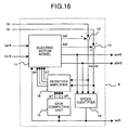
- Fig. 16 is a diagram which shows the internal configuration of the adaptive observer 9 shown in Fig. 15.
- reference numeral 11 denotes an electric motor model
- 12 and 13 denotes subtractors
- 14 denotes a speed identifier
- 15 denotes a gain computing unit
- 16 denotes a deviation amplifier.
- the electric motor model 11 calculates an a-axis estimated current ia0 and a b-axis estimated current ib0 on the static biaxial coordinates (a-b axis) and the a-axis estimated rotor magnetic flux par0 and the b-axis estimated rotor magnetic flux pbr0 based on the a-axis voltage command va* and the b-axis voltage command vb* on the static biaxial coordinates (a-b axis), the estimated rotational speed wr0, and deviations e1, e2, e3, and e4 (to be described later) according to the following equation (4),
- the subtractor 12 outputs a result obtained by subtracting the a-axis current ia from the a-axis estimated current ia0 as an a-axis current deviation ea.
- the subtractor 13 outputs a result obtained by subtracting the b-axis current ib from the b-axis estimated current ib0 as a b-axis current deviation eb.
- the speed identifier 14 outputs the estimated rotational speed wr0 based on the Par0, pbr0, ea, and eb according to the following equation (5),
- the deviation amplifier 16 amplifies the current deviations ea and eb by the gains g1, g2, g3, and g4 to output the deviations e1, e2, e3, and e4. More specifically, the deviation amplifier 16 outputs the deviations e1, e2, e3, and e4 to the electric motor model 11 according to the following equation (10),
- the adaptive observer 9 outputs the estimated rotor magnetic fluxes par0 and pbr0 and the estimated rotational speed wr0.
- the frequency components of the voltages va* and vb* input to the adaptive observer become high when the synchronous motor operates at a high rotational speed because the adaptive observer is constituted on the two static axes. Therefore, when the calculation of the adaptive observer is realized by a computer, sampling of the voltages va* and vb* must be performed at a very short cycle to drive the synchronous motor at a high rotational speed.
- the conventional control apparatus for a synchronous motor cannot be easily applied to a synchronous motor in which an inductance Ld in the direction (d-axis direction) of a rotor magnetic flux is not equal to an inductance Lq in the direction (q-axis direction) perpendicular to the direction of the rotor magnetic flux, i.e., a synchronous motor in which a salient-pole ratio is not 1.
- a synchronous motor in which a salient-pole ratio is not 1 an inductance on static biaxial coordinates changes depending on the position of a rotor.
- the conventional control apparatus for a synchronous motor constitutes an adaptive observer on static biaxial coordinates and cannot handle an inductance as a constant value. For this reason, the control apparatus cannot be easily applied to the synchronous motor.
- gains g1, g2, g3, and g4 are determined such that the pole of the adaptive observer is in proportion to the pole of the synchronous motor.
- the pole of the adaptive observer decreases because the pole of the synchronous motor is small. Therefore, the response of an estimated magnetic flux is deteriorated, the characteristics of the control system itself is also deteriorated.
- the feedback gains g1, g2, g3, and g4 are set such that the pole of the adaptive observer 9 is in proportion to the unique pole of the synchronous motor 1.
- these gains are not appropriate to perform state estimation. For this reason, the actual rotational speed wr deviates from the estimated rotational speed wr0, and thereby the accuracy of magnetic flux estimation is deteriorated.
- the control apparatus for a synchronous motor comprises a current detector which detects a current of a synchronous motor, a coordinate converter which coordinate-converts the current obtained from the current detector into a current on rotational biaxial coordinates (d-q axis) rotated at an angular frequency, a current controller which outputs a voltage command on the rotational biaxial coordinates (d-q axis) such that a current on the rotational biaxial coordinates (d-q axis) follows a current command on the rotational biaxial coordinates (d-q axis), a coordinate converter which coordinate-converts the voltage command on the rotational biaxial coordinates (d-q axis) obtained from the current controller into three-phase voltage commands, an adaptive observer which calculates the angular frequency, an estimated current of the synchronous motor, an estimated rotor magnetic flux, and an estimated rotational speed based on the current on the rotational biaxial coordinates (d-q axis) and the voltage command on the rotational biaxial coordinate
- the adaptive observer since the adaptive observer calculates the angular frequency such that the q-axis component of the estimated rotor magnetic flux is zero, the adaptive observer can be constituted on the rotational two axes.
- the adaptive observer has an electric motor model in which a salient-pole ratio is not 1.
- the adaptive observer since the adaptive observer has the electric motor model in which the salient-pole ratio is not 1, the synchronous motor can be controlled at a high rotational speed even by an inexpensive computing unit, and the scope of application can be expanded to a synchronous motor having salient-pole properties.
- the adaptive observer has a feedback gain which is given by a function of the estimated rotational speed such that transmission characteristics from a rotational speed error of the synchronous motor to an estimated magnetic flux error are averaged in a frequency area.
- the adaptive observer since the adaptive observer has the feedback gain which is given by the function of the estimated rotational speed such that the transmission characteristics from the rotational speed error of the synchronous motor to the estimated magnetic flux error are averaged in the frequency area, the pole of the synchronous motor can be arbitrary set even if the synchronous motor is driven at a low rotational speed, and the synchronous motor can be stably controlled without deteriorating the accuracy of magnetic flux estimation.
- the adaptive observer calculates an estimated rotational speed based on a q-axis component of a deviation between a current on the rotational biaxial coordinates (d-q axis) and the estimated current.
- the estimated rotational speed can be calculated based on the q-axis component of the deviation between the current on the rotational biaxial coordinates (d-q axis) and the estimated current, the number of times of multiplication and division required for calculation can be reduced by omitting a product between the q-axis component of the deviation between the current and the estimated current and an estimated rotor magnetic flux, and a calculation time can be shortened.
- the adaptive observer calculates an estimated rotational speed based on a value obtained by dividing the q-axis component of the deviation between the current on the rotational biaxial coordinates (d-q axis) and the estimated current by the estimated rotor magnetic flux.
- the estimated rotational speed is calculated based on the value obtained by dividing the q-axis component of the deviation between the current on the rotational biaxial coordinates (d-q axis) and the estimated current by the estimated rotor magnetic flux, even though the rotor magnetic flux changes depending on a temperature, an estimated response of the rotational speed can be kept constant.
- the control apparatus for a synchronous motor includes a speed controller which outputs a current command on the rotational biaxial coordinates (d-q axis) such that the current command is equal to a rotational speed command based on at least one value of an estimated rotational speed obtained from the adaptive observer and the angular frequency.
- the speed controller which provides the current command on the rotational biaxial coordinates (d-q axis) such that the current command is equal to the rotational speed command based on at least one value of the estimated rotational speed obtained from the adaptive observer and the angular frequency is arranged, the synchronous motor can be controlled in speed.
- Fig. 1 is a block diagram which shows the entire configuration of a control apparatus for a synchronous motor according to a first embodiment of the present invention
- Fig. 2 is a block diagram which shows the configuration of an adaptive observer according to the first embodiment
- Fig. 3 is a diagram which shows the configuration of an electric motor model 11a
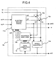
- Fig. 4 is a diagram which shows the configuration of an adaptive observer 9b
- Fig. 5 is a diagram which shows the configuration of an electric motor model 11b
- Fig. 6 is a diagram which shows the configuration of an adaptive observer 9c
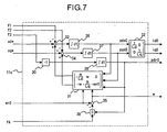
- Fig. 7 is a diagram which shows the configuration of an electric motor model 11c
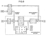
- Fig. 8 is a block diagram which shows a synchronous motor 1 when system noise and measurement noise are input as disturbance
- Fig. 9 shows examples of feedback gains h11, h12, h21, h22, h31, h32, h41, and h42 obtained by equation (46),
- Fig. 10 is a graph on which magnitudes of the maximum pole of the adaptive observer when an arbitrary positive number ⁇ is changed are plotted
- Fig. 11 shows examples of feedback gains h11, h12, h21, h22, h31, h32, h41, and h42 related to a synchronous motor in which a salient-pole ratio is not 1
- Fig. 12 is a graph on which magnitudes of the maximum pole of an adaptive observer when the positive number ⁇ is changed are plotted
- Fig. 12 is a graph on which magnitudes of the maximum pole of an adaptive observer when the positive number ⁇ is changed are plotted
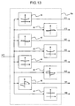
- Fig. 13 is a diagram which shows the internal configuration of a gain computing unit 15d
- Fig. 14 is a diagram which shows the configuration of a known speed control unit which amplifies a deviation between a rotational speed command and an estimated rotational speed
- Fig. 15 is a block diagram which shows the entire configuration of a conventional control apparatus for a synchronous motor
- Fig. 16 is a diagram which shows the internal configuration of a conventional adaptive observer 9.
- Calculation of the angular frequency w given by the equation (14) corresponds to calculation in which the angular frequency w is calculated such that a q-axis component of an estimated rotor magnetic flux is zero. Therefore, in this embodiment, the rotational biaxial coordinate axis rotated at the angular frequency w given by the equation (14) is defined as a d-q axis.
- the direction of an estimated rotor magnetic flux vector is made equal to the direction of the d-axis.
- voltage commands va* and vb* on the static biaxial coordinates input to the conventional adaptive observer are AC.
- voltage commands vd* and vq* input to the adaptive observer constituted by the equations (13), (14), (17), and (18) are DC quantities because the voltage commands vd* and vq* are variables on the rotational biaxial coordinate axis.
- the adaptive observer constituted by the equations (13), (14), (17), and (18) can solve this problem because the voltage commands vd* and vq* are DC quantities.
- Fig. 1 is a diagram which shows the configuration of the control apparatus for a synchronous motor according to the first embodiment.
- reference numerals 1, 2, 3, and 4 denote the same parts in the conventional apparatus, and an explanation thereof will be omitted.
- Reference numerals 5a and 8a denote coordinate converters
- reference numeral 9a denotes an adaptive observer
- 17 denotes an integrator.
- the coordinate converter 5a coordinate-converts a d-axis voltage command vd* and a q-axis voltage command vq* on the rotational biaxial coordinate axis (d-q axis) into three-phase voltage commands vu* vv*, and vw* based on a rotational position th0 obtained from the integrator 17.
- the coordinate converters 8a outputs an a-axis current ia and a b-axis current ib on the static biaxial coordinates (a-b axis) and a d-axis current id and a q-axis current iq on the rotational biaxial coordinates (d-q axis) based on a U-phase current iu and a V-phase current iv obtained from the current detectors 2 and the rotational position th0 obtained from the integrator 17.
- the adaptive observer 9a outputs an estimated rotor magnetic flux pdr0, the angular frequency w, and an estimated rotational speed wr0 based on the d-axis voltage command vd* and the q-axis voltage command vq* on the rotational biaxial coordinate axis (d-q axis) and the d-axis current command id and the q-axis current command iq on the rotational biaxial coordinate axis (d-q axis).
- the integrator 17 integrates the angular frequency w obtained from the adaptive observer 9a to output the rotational position th0.
- Fig. 2 is a diagram which shows the internal configuration of the adaptive observer 9a.
- reference numeral 15 denotes the same part in the conventional apparatus, and an explanation thereof will be omitted.
- Reference numeral 11a denotes an electric motor model
- 12a and 13a denote subtractors
- 14a denotes a speed identifier
- 16a denotes a deviation amplifier.
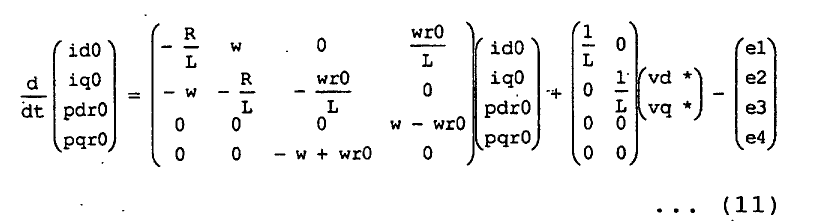
- the electric motor model 11a calculates a d-axis estimated current id0 and a q-axis estimated current iq0 on the rotational biaxial coordinates (d-q axis), the estimated rotor magnetic flux pdr0, and the angular frequency w according to equations (14) and (17) based on the d-axis voltage command vd* and the q-axis voltage command vq* on the rotational biaxial coordinates (d-q axis), the estimated rotor speed wr0, and deviations e1, e2, e3, and e4 (to be described later).
- the subtractor 12a outputs a result obtained by subtracting the d-axis current id from the d-axis estimated current id0 as a d-axis current deviation ed.
- the subtractor 13a outputs a result obtained by subtracting the q-axis current iq from the q-axis estimated current iq0 as a q-axis current deviation eq.
- the speed identifier 14a outputs the estimated rotational speed wr0 according to equation (18) based on the currents pdr0 and eq.
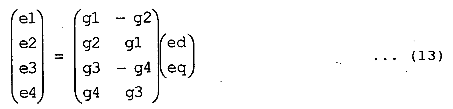
- the gain computing unit 15 outputs gains g1, g2, g3, and g4 according to equations (6) to (9) based on the estimated rotational speed wr0.
- the deviation amplifier 16a amplifies the current deviations ed and eq by the gains g1, g2, g3, and g4 to output the deviations e1, e2, e3, and e4. More specifically, the deviation amplifier 16a outputs the deviations e1, e2, e3, and e4 to the electric motor model 11a according to the equation (13).
- the adaptive observer 9a outputs the estimated rotor magnetic flux pdr0, the angular frequency w, and the estimated rotational speed wr0.
- Fig. 3 is a diagram which shows the configuration of the electric motor model 11a.
- reference numerals 18 and 19 denote matrix gains
- 20 to 23 denote adder-subtractors
- 24 to 26 denote integrators
- 27 denote a divider.
- the matrix gain 18 outputs a calculation result of the second term of the right side of the equation (17) based on the input voltage commands vd* and vq*.
- the matrix gain 19 outputs a calculation result of the first term of the right side of the equation (17) based on the input angular frequency w, the input estimated rotational speed wr0, the. input estimated currents iq0 and iq0, and the input estimated rotor magnetic flux pdr0.
- the adder-subtractors 20 to 22 add and subtract the first term, the second term, and the third term of the right side of the equation (17) to output d/dt id0, d/dt iq0, and d/dt pdr0, respectively.
- the integrator 24 outputs id0 by integrating the d/dt id0.
- the integrator 25 outputs iq0 by integrating the d/dt iq0.
- the integrator 26 outputs pdr0 by integrating the d/dt pdr0.
- the divider 27 outputs a calculation result of the second term of the right side of the equation (14) based on the input e4 and pdr0.
- the subtractor 23 subtracts an output from the divider 27 from the estimated rotational speed wr0 to output the right side of the equation (14), i.e., the angular frequency w.
- the electric motor model 9a calculates the d-axis estimated current id0 and the q-axis estimated current iq0 on the rotational biaxial coordinates (d-q axis), the estimated rotor magnetic flux pdr0, and the angular frequency w according to the equations (14) and (17).
- the adaptive observer is constituted on the rotational two axes, and therefore even though the synchronous motor operates at a high rotational speed, the frequency components of the voltages vd* and vq* input to the adaptive observer are DC components. For this reason, even though calculation of the adaptive observer is realized by a computing unit, sampling of the voltages vd* and vq* need not be performed at a very short cycle. Therefore, even though an inexpensive computing. unit is used, the synchronous motor can be controlled at a high rotational speed.
- the apparatus can be applied to a synchronous motor the inductance of which has no salient-pole properties.
- the apparatus cannot be directly applied to the synchronous motor which has salient-pole properties without any change to the apparatus. Therefore, in the second embodiment, a control apparatus for a synchronous motor which can be applied to a synchronous motor which has salient-pole properties will be explained.
- an inductance in the direction of the rotor magnetic flux is different from an inductance in the direction perpendicular to the direction of the rotor magnetic flux, and therefore the inductance in the direction of the rotormagnetic flux is defined as Ld, and the inductance in the direction perpendicular to the direction of the rotor magnetic flux is defined as Lq in the following description.
- the coefficients of the equation (21) constitute feedback gains with reference to eight types of elements g11 to g41 obtained in consideration of a salient-pole ratio, e.g., the following equations (23) to (30).
- g11 -(k - 1)
- R Ld g12 -(k - 1)
- Ld Lq wr0 g21 (k - 1)
- Lq Ld wr0 g22 -(k - 1)
- R Lq g31 k
- g32 k
- the configuration of the second embodiment merely uses a synchronous motor 1b in place of the synchronous motor 1 and uses an adaptive observer 9b in place of the adaptive observer 9a in Fig. 1 (not shown).
- the synchronous motor 1b has a permanent magnet as a rotor the rotor magnetic flux of which is pdr.
- the inductance in the direction (d-axis direction) of the rotor magnetic flux is Ld
- the inductance in the direction (q-axis direction) perpendicular to the direction of the rotor magnetic flux is Lq.
- Fig. 4 is a diagram which shows the configuration of the adaptive observer 9b.
- reference numerals 12a, 13a, and 14a denote the same parts in the first embodiment, and an explanation thereof will be omitted.
- Reference numeral 11b denotes an electric motor model
- 15b denotes a gain computing unit
- 16b denotes a deviation amplifier.
- the electric motor model 11b calculates a d-axis estimated current id0 and a q-axis estimated current iq0 on the rotational biaxial coordinates (d-q axis), a d-axis estimated rotor magnetic flux pdr0, and an angular frequency w according to the equations (20) and (21) based on the d-axis voltage command vd* and the q-axis voltage command vq* on the rotational biaxial coordinates (d-q axis), the estimated rotational speed wr0, and deviations e1, e2, e3, and e4 (to be described later).
- the gain computing unit 15b outputs gains g11, g12, g21, g22, g31, g32, g41, and g42 according to the equations (23) to (30) based on the estimated rotational speed wr0.
- the deviation amplifier 16b amplifies the current deviations ed and eq by the gains g11, g12, g21, g22, g31, g32, g41, and g42 to output deviations e01, e02, e03, and e04. More specifically, the deviation amplifier 16b outputs the deviations e01, e02, e03, and e04 to the electric motor model 11b according to the equation (22).
- the adaptive observer 9b outputs the estimated rotor magnetic flux pdr0, the angular frequency w, and the estimated rotational speed wr0.
- Fig. 5 is a diagram which shows the configuration of the electric motor model 11b.
- reference numerals 20 to 27 denote the same parts in the first embodiment, and an explanation thereof will be omitted.
- Reference numerals 18b and 19b denote matrix gains.
- the matrix gain 18b outputs a calculation result of the second term of the right side of the equation (20) based on the input voltage commands vd* and vq*.
- the matrix gain 19b outputs a calculation result of the first term of the right side of the equation (20) based on the input angular frequency w, the input estimated rotational speed wr0, the input estimated currents id0 and iq0, and the input estimated rotor magnetic flux pdr0.
- the adder-subtractors 20 to 22 add and subtract the first, second, and third terms of the right side of the equation (20) to output d/dt id0, d/dt iq0, and d/dt pdr0, respectively.
- the divider 27 outputs a calculation result of the second term of the right side of the equation (21) based on the input e04 and pdr0.
- the subtractor 23 subtracts the output of the divider 27 from the estimated rotational speed wr0 to output the right side of the equation (21), i.e., the angular frequency w.
- the electric motor model 9b calculates the d-axis estimated current id0 and the q-axis estimated current iq0 on the rotational biaxial coordinates (d-q axis), the d-axis estimated rotor magnetic flux pdr0, and the angular frequency w according to the equations (20) and (21).
- the synchronous motor can be controlled at a high rotational speed by an inexpensive computing unit, and the scope of application can be expanded to the synchronous motor having a salient-pole properties.
- the state variables may be handled as pds0, pqs0, pdr0, and pqr0.
- Reference symbols pds0 and pqs0 denote a d-axis component and a q-axis component of estimated armature reaction on a rotational biaxial coordinates defined by the following equation (31),
- Fig. 6 is a diagram which shows the configuration of the adaptive observer 9c.
- numerals 12a, 13a, and 14a denote the same parts in the first and second embodiments, and an explanation thereof will be omitted.
- Reference numeral 11c denotes an electric motor model
- 15c denotes a gain computing unit
- 16c denotes a deviation amplifier.
- the electric motor model 11c calculates a d-axis estimated current id0 and a q-axis estimated current iq0 on the rotational biaxial coordinates (d-q axis), a d-axis estimated rotor magnetic flux pdr0, and an angular frequency w according to equations (32) and (33) based on the d-axis voltage command vd* and the q-axis voltage command vq* on the rotational biaxial coordinates (d-q axis), the estimated rotational speed wr0, and deviations f1, f2, f3, and f4 (to be described later).
- the gain computing unit 15c outputs gains h11, h12, h21, h22, h31, h32, h41, and h42 based on the estimated rotational speed wr0.
- the deviation amplifier 16c amplifies the current deviations ed and eq by the gains h11, h12, h21, h22, h31, h32, h41, and h42 to output deviations f1, f2, f3, and f4. More specifically, the deviation amplifier 16c outputs the deviations f1, f2, f3, and f4 to the electric motor model 11c according to the equation (34).
- the adaptive observer 9c outputs the estimated rotor magnetic flux pdr0, the angular frequency w, and the estimated rotational speed wr0.
- Fig. 7 is a diagram which shows the configuration of the electric motor model 11c.
- reference numeral 30 denotes a gain
- 31 and 32 denote matrix gains
- 33 and 34 denote adder-subtractors
- 35 denotes a subtractor
- 36 to 38 denote integrators
- 39 denotes a divider.
- the matrix gain 31 outputs calculation results of the first and second lines of the first term of the right side of the equation (32) based on the input angular frequency w, the input estimated rotational speed wr0, the input estimated armature reactions pds0 and pqs0, and the input estimated rotor magnetic flux pdr0.
- the adder-subtractors 33 and 34 add and subtract the second and third lines of the first, second, and third terms of the right side of the equation (32) to output d/dt pds0 and d/dt pqs0, respectively.
- the gain 30 makes the deviation f3 -1 times to calculate the third line of the right side of the equation (32), thereby outputting d/dt pdr0.
- the integrators 36 to 38 integrate the d/dt pds0, d/dt pqs0, and d/dt pdr0 to output pds0, pqs0, and pdr0.
- the matrix gain 32 outputs estimated currents id0 and iq0 according to the equation (35) based on the pds0 and pqs0.
- the divider 39 outputs a calculation result of the second term of the right side of the equation (33) based on the input f4 and pdr0.
- the subtractor 35 subtracts an output of the divider 39 from the estimated rotational speed wr0 to output the right side of the equation (33), i.e., the angular frequency w.
- the electric motor model 9c calculates the d-axis estimated current id0 and the q-axis estimated current iq0 on the rotational biaxial coordinates (d-q axis), the estimated rotor magnetic flux pdr0, and the angular frequency w according to the equations (32), (33), and (35).
- the third embodiment has state variables which are different from those of the second embodiment, the third embodiment is essentially equivalent to the second embodiment. Therefore, as in the second embodiment, the synchronous motor can be controlled at a high rotational speed even by an inexpensive computing unit. In addition, the scope of application can be expanded to the synchronous motor having salient-pole properties.
- the feedback gains of the adaptive observer are determined to be in proportion to the unique pole of the synchronous motor.
- the gains g1, g2, g3, and g4 expressed by the equations (6) to (9) in the adaptive observer are determined, and when the synchronous motor is driven at a low rotational speed, the pole of the synchronous motor decreases. Accordingly, the pole of the adaptive observer also decreases. For this reason, the response of an estimated magnetic flux is deteriorated, and the characteristics of the control system itself are also deteriorated.
- an actual rotational speedwr is deviated from the estimated rotational speed wr0, the estimation accuracy of the estimated magnetic flux is deteriorated disadvantageously.
- the fourth embodiment will explain a method of averaging transmission characteristics between a speed error of the synchronous motor and a magnetic flux estimation error in a frequency area.
- a control apparatus for a synchronous motor which uses this method, deterioration in accuracy of magnetic flux estimation caused by the deviation between the actual rotational speed wr and the estimated rotational speed wr0 can be suppressed, and the magnitude of the pole of the observer can be kept at a desired value. For this reason, a rotational speed can be preferably estimated.
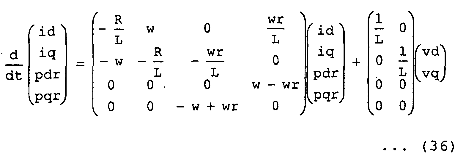
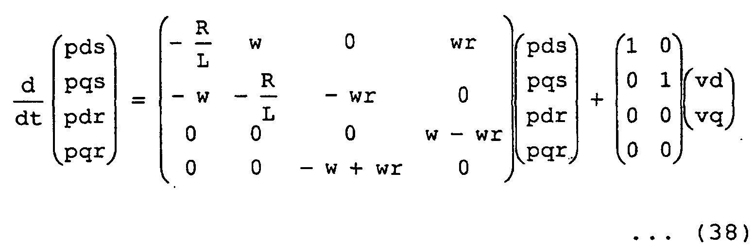
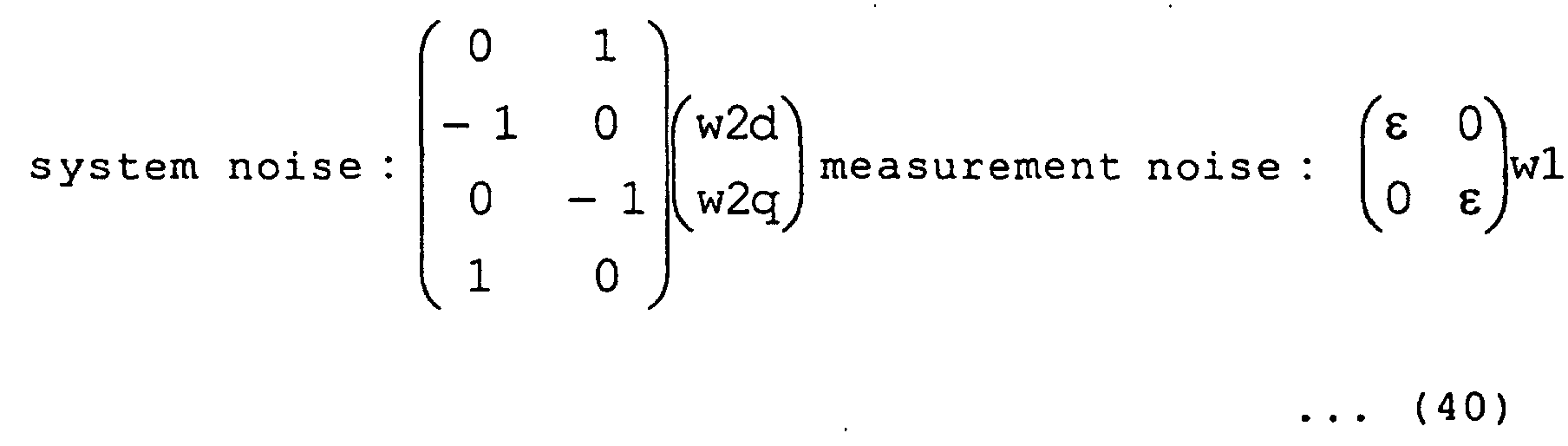
- equation (39) is an equation in which system noise and measurement noise expressed by equation (40) are input as disturbance to an ideal synchronous motor expressed by the equation (38).
- Fig. 8 is a block diagram of the synchronous motor 1 used at this time.
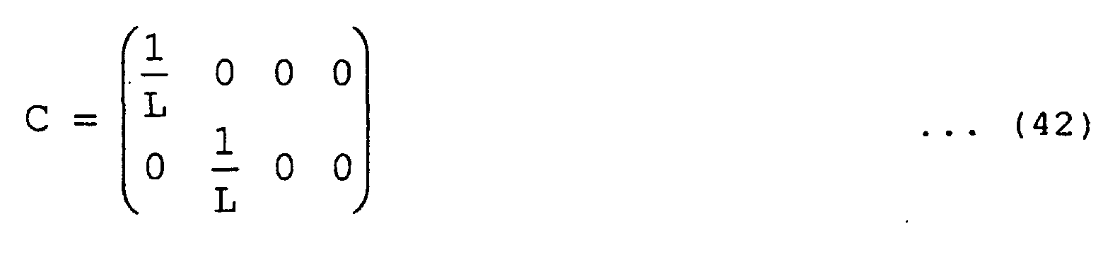
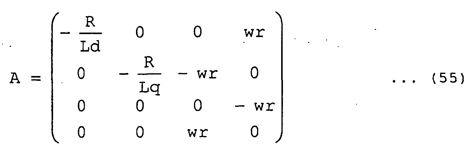
- Matrixes A, C, Q, and R are defined by equations (41), (42), (43), and (44).
- the feedback gains h11, h12, h21, h22, h31, h32, h41, and h42 are functions of the rotational speeds.
- the feedback gains h11, h12, h21, h22, h31, h32, h41, and h42 may be prepared as a table with respect to the respective rotational speeds, and the feedback gains h11, h12, h21, h22, h31, h32, h41, and h42 may be determined as functions of estimated rotational speeds in place of the rotational speeds.
- Fig. 9 shows examples of the feedback gains h11, h12, h21, h22, h31, h32, h41, and h42 obtained by giving an appropriate number ⁇ according to equation (46).
- the relationships shown in Fig. 9 are merely prepared in a gain computing unit as a table. Since the gain computing unit cannot detect an actual rotational speed, the functions of the estimated rotational speeds may be set.
- Fig. 10 is a graph on which magnitudes of the maximum pole of the adaptive observer when an arbitrary positive number ⁇ is changed are plotted. As is apparent from Fig. 10, when the magnitude of ⁇ is changed, the magnitude of the maximum pole of the adaptive observer also changes. When this phenomenon is used, the magnitude of the pole of the observer can be determined to be a desired value.
- the pole of the synchronous motor can be arbitrarily set even though the synchronous motor is driven at a low rotational speed, and the gains are appropriate to perform state estimation when the estimated rotational speed is deviated from the actual rotational speed. For this reason, the synchronous motor can be stably controlled without deteriorating the accuracy of magnetic flux estimation.
- the control apparatus related to the synchronous motor in which the salient-pole ratio is 1 has been explained.
- the present invention can also be applied to the control apparatus for a synchronous motor in which a salient-pole ratio is not 1 and which is described in the third embodiment.
- a solution P of the Riccati equation (45) is calculated by using equations (55) and (56) obtained in consideration of a salient-pole ratio without using the equations (41) and (42), and the solution P may be substituted to the equation (46).
- Fig. 11 shows examples of feedback gains h11, h12, h21, h22, h31, h32, h41, and h42 which can be obtained by giving an appropriate number ⁇ according to the equation (46) and which is related to a synchronous motor 1a in which the salient-pole ratio is not 1.
- Fig. 12 is a graph on which magnitudes of the maximum pole of an adaptive observer when an arbitrary positive number ⁇ is changed. As is apparent from Fig. 12, when the magnitude of ⁇ is changed, the magnitude of the maximum pole of the adaptive observer also changes.
- the gain computing unit 15c may be merely replaced with a gain computing unit 15d in Fig. 6 of the fourth embodiment.
- Fig. 13 is a diagram which shows the internal configuration of the gain computing unit 15d in the fifth embodiment.
- Reference numerals 40 to 47 denote gain tables.
- the gain table 40 stores the relation of the feedback gain h11 derived in advance shown in Fig. 11 and outputs the value of the feedback gain h11 based on the input estimated rotational speed wr0.
- the gain tables 41 to 47 store the relations of the feedback gains h12, h21, h22, h31, h32, h41, and h42 derived in advance and shown in Fig. 11, and output the values of the feedback gains h12, h21, h22, h31, h32, h41, and h42 based on the input estimated rotational speed wr0, respectively.
- the pole of the synchronous motor can be arbitrarily set, and gains are appropriate to perform state estimation when an estimated rotational speed is deviated from an actual rotational speed. For this reason, the synchronous motor can be stably controlled without deteriorating the accuracy of magnetic flux estimation.
- the speed identifier 14 performs calculation based on the equation (18)
- the right side of the equation (18) may be multiplied and divided by an arbitrary positive number.
- the estimated rotational speed wr0 may be given by equation (57) or equation (58) obtained by dividing the equation (18) by pdr0 or (pdr0) ⁇ 2.
- speed control maybe performed by using a speed control unit which amplifies a deviation between a rotational speed command and an estimated rotational speed.
- Fig. 14 is a diagram which shows the configuration of a known speed control unit which amplifies a deviation between a rotational speed command and an estimated rotational speed.
- reference numeral 48 denotes a subtractor
- 49 denotes a speed controller.
- the subtractor 48 subtracts an estimated rotational speed wr0 from a rotational speed command wr* and outputs a deviation obtained through the subtraction to the speed controller 49.
- the speed controller 49 outputs a q-axis current command iq* based on the deviation between the rotational speed command wr* and the estimated rotational speed wr0.
- the synchronous motor can be controlled in speed.
- an angular frequency w is used in place of the estimated rotational speed wr0, the same effect as described above can be obtained.
- the adaptive observer calculates the angular frequency w such that the q-axis component of the estimated rotor magnetic flux is zero, so that the adaptive observer can be constituted on rotational two axes.
- the frequency components of the voltages vd* and vq* input to the adaptive observer are DC components. For this reason, sampling of the voltages vd* and vq* need not be performed at a very short cycle even though calculation of the adaptive observer is realized by a computing unit. Therefore, the synchronous motor can be controlled at a high rotational speed by an inexpensive computing unit.
- the adaptive observer since the adaptive observer has the electric motor model in which the salient-pole ratio is not 1, the synchronous motor can be controlled at a high rotational speed even by an inexpensive computing unit, and the scope of application can be expanded to a synchronous motor having salient-pole properties.
- the control apparatus since the control apparatus includes the adaptive observer which has the feedback gain which is given by the function of the estimated rotational speed such that the transmission characteristics from the rotational speed error of the synchronous motor to the estimated magnetic flux error are averaged in the frequency area, the pole of the synchronous motor can be arbitrary set even if the synchronous motor is driven at a low rotational speed, and the synchronous motor can be stably controlled without deteriorating the accuracy of magnetic flux estimation.
- control apparatus since the control apparatus includes the adaptive observer which calculates the estimated rotational speed based on the q-axis component of the deviation between the current on the rotational biaxial coordinates (d-q axis) and the estimated current, the number of times of multiplication and division required for calculation can be reduced by omitting a product between the q-axis component of the deviation between the current and the estimated current and an estimated rotor magnetic flux. For this reason, calculation time can be shortened.
- control apparatus since the control apparatus includes the adaptive observer which calculates the estimated rotational speed based on the value obtained by dividing the q-axis component of the deviation between the current on the rotational biaxial coordinates (d-q axis) and the estimated current by the estimated rotor magnetic flux, even though the rotor magnetic flux changes depending on a temperature, an estimated response of the rotational speed can be kept constant.
- the control apparatus since the control apparatus includes the speed controller which gives the current command on the rotational biaxial coordinates (d-q axis) such that the current command is equal to the rotational speed command based on at least one value of the estimated rotational speed obtained from the adaptive observer and the angular frequency w, the synchronous motor can be controlled in speed.
- control apparatus for a synchronous motor is suitably used as a control apparatus used in various synchronous motors each including an adaptive observer.
Landscapes
- Engineering & Computer Science (AREA)
- Power Engineering (AREA)
- Control Of Ac Motors In General (AREA)
- Control Of Multiple Motors (AREA)
- Control Of Motors That Do Not Use Commutators (AREA)
Abstract
Description









| h11 = Ld g11, | h12 = Ld g12 |
| h21 = Lq g21, | h22 = Lq g22 |
| h31 = g31, | h32 = g32 |
| h41 = g41, | h42 = g42 |









Claims (6)
- A control apparatus for a synchronous motor comprising:wherein the adaptive observer calculates the angular frequency such that a q-axis component of the estimated rotor magnetic flux is zero.a current detector which detects a current of a synchronous motor;a coordinate converter which coordinate-converts the current obtained from the current detector into a current on rotational biaxial coordinates (d-q axis) rotated at an angular frequency;a current controller which outputs a voltage command on the rotational biaxial coordinates (d-q axis) such that a current on the rotational biaxial coordinates (d-q axis) follows a current command on the rotational biaxial coordinates (d-q axis);a coordinate converter which coordinate-converts the voltage command on the rotational biaxial coordinates (d-q axis) obtained from the current controller into three-phase voltage commands;an adaptive observer which calculates the angular frequency, an estimated current of the synchronous motor, an estimated rotor magnetic flux, and an estimated rotational speed based on the current on the rotational biaxial coordinates (d-q axis) and the voltage command on the rotational biaxial coordinates (d-q axis); andan inverter which applies a voltage to the synchronous motor based on the voltage command,
- The control apparatus for a synchronous motor according to claim 1, wherein the adaptive observer has an electric motor model in which a salient-pole ratio is not 1.
- The control apparatus for a synchronous motor according to claim 1, wherein the adaptive observer has a feedback gain which is given by a function of the estimated rotational speed such that transmission characteristics from a rotational speed error of the synchronous motor to an estimated magnetic flux error are averaged in a frequency area.
- The control apparatus for a synchronous motor according to claim 1, wherein the adaptive observer calculates the estimated rotational speed based on the q-axis component of the deviation between the current on the rotational biaxial coordinates (d-q axis) and the estimated current.
- The control apparatus for a synchronous motor according to claim 1, wherein the adaptive observer calculates the estimated rotational speed based on a value obtained by dividing the q-axis component of the deviation between the current on the rotational biaxial coordinates (d-q axis) and the estimated current by the estimated rotor magnetic flux.
- The control apparatus for a synchronous motor according to claim 1, comprising a speed controller which outputs a current command on the rotational biaxial coordinates (d-q axis) such that the current command is equal to a rotational speed command based on at least one value of an estimated rotational speed obtained from the adaptive observer and the angular frequency.
Applications Claiming Priority (1)
| Application Number | Priority Date | Filing Date | Title |
|---|---|---|---|
| PCT/JP2001/003530 WO2002091558A1 (en) | 2001-04-24 | 2001-04-24 | System for controlling synchronous motor |
Publications (3)
| Publication Number | Publication Date |
|---|---|
| EP1303035A1 true EP1303035A1 (en) | 2003-04-16 |
| EP1303035A4 EP1303035A4 (en) | 2006-01-11 |
| EP1303035B1 EP1303035B1 (en) | 2016-08-17 |
Family
ID=11737273
Family Applications (1)
| Application Number | Title | Priority Date | Filing Date |
|---|---|---|---|
| EP01922063.1A Expired - Lifetime EP1303035B1 (en) | 2001-04-24 | 2001-04-24 | System for controlling synchronous motor |
Country Status (6)
| Country | Link |
|---|---|
| US (2) | US6825637B2 (en) |
| EP (1) | EP1303035B1 (en) |
| JP (1) | JP4672236B2 (en) |
| CN (1) | CN1244196C (en) |
| TW (1) | TW517443B (en) |
| WO (1) | WO2002091558A1 (en) |
Cited By (5)
| Publication number | Priority date | Publication date | Assignee | Title |
|---|---|---|---|---|
| US6825637B2 (en) * | 2001-04-24 | 2004-11-30 | Mitsubishi Denki Kabushiki Kaisha | System for controlling synchronous motor |
| WO2007090718A1 (en) * | 2006-02-09 | 2007-08-16 | Continental Automotive Gmbh | Method and device for operating a synchronous machine |
| RU2481693C1 (en) * | 2009-04-27 | 2013-05-10 | Мицубиси Электрик Корпорейшн | Device of power conversion |
| EP2808998A4 (en) * | 2012-01-24 | 2016-06-29 | Mitsubishi Electric Corp | CONTROL DEVICE FOR AN AC POWER ROTATION MACHINE |
| EP2343798A3 (en) * | 2010-01-08 | 2017-08-23 | LS Industrial Systems Co., Ltd | Apparatus and method for controlling operation of inverter system |
Families Citing this family (74)
| Publication number | Priority date | Publication date | Assignee | Title |
|---|---|---|---|---|
| US20050046375A1 (en) * | 2002-07-31 | 2005-03-03 | Maslov Boris A. | Software-based adaptive control system for electric motors and generators |
| JP4230276B2 (en) * | 2003-05-19 | 2009-02-25 | 本田技研工業株式会社 | Brushless DC motor control device |
| US7276877B2 (en) * | 2003-07-10 | 2007-10-02 | Honeywell International Inc. | Sensorless control method and apparatus for a motor drive system |
| JP4619040B2 (en) * | 2004-05-14 | 2011-01-26 | アイシン・エィ・ダブリュ株式会社 | Electric drive control device, electric drive control method, and program |
| WO2006008846A1 (en) * | 2004-07-21 | 2006-01-26 | Mitsubishi Denki Kabushiki Kaisha | Ac rotary machine constant measuring apparatus |
| US7211984B2 (en) * | 2004-11-09 | 2007-05-01 | General Motors Corporation | Start-up and restart of interior permanent magnet machines |
| US8248577B2 (en) | 2005-05-03 | 2012-08-21 | Asml Netherlands B.V. | Lithographic apparatus and device manufacturing method |
| JP4022630B2 (en) * | 2005-06-27 | 2007-12-19 | 国立大学法人徳島大学 | Power conversion control device, power conversion control method, and program for power conversion control |
| JP2007043859A (en) * | 2005-08-05 | 2007-02-15 | Yaskawa Electric Corp | Electric power conversion device and electric power conversion method |
| JP4425193B2 (en) * | 2005-08-16 | 2010-03-03 | 三洋電機株式会社 | Motor position sensorless control device |
| ATE445930T1 (en) * | 2006-06-15 | 2009-10-15 | Abb Oy | METHOD AND SYSTEM RELATED TO PERMANENT MAGNETIC SYNCHRONOUS MACHINES |
| JP4800861B2 (en) * | 2006-06-21 | 2011-10-26 | 三菱電機株式会社 | AC rotating machine control device |
| US8950206B2 (en) | 2007-10-05 | 2015-02-10 | Emerson Climate Technologies, Inc. | Compressor assembly having electronics cooling system and method |
| US7895003B2 (en) * | 2007-10-05 | 2011-02-22 | Emerson Climate Technologies, Inc. | Vibration protection in a variable speed compressor |
| US8459053B2 (en) * | 2007-10-08 | 2013-06-11 | Emerson Climate Technologies, Inc. | Variable speed compressor protection system and method |
| US8539786B2 (en) * | 2007-10-08 | 2013-09-24 | Emerson Climate Technologies, Inc. | System and method for monitoring overheat of a compressor |
| US8418483B2 (en) | 2007-10-08 | 2013-04-16 | Emerson Climate Technologies, Inc. | System and method for calculating parameters for a refrigeration system with a variable speed compressor |
| US9541907B2 (en) * | 2007-10-08 | 2017-01-10 | Emerson Climate Technologies, Inc. | System and method for calibrating parameters for a refrigeration system with a variable speed compressor |
| US20090092501A1 (en) * | 2007-10-08 | 2009-04-09 | Emerson Climate Technologies, Inc. | Compressor protection system and method |
| US8448459B2 (en) * | 2007-10-08 | 2013-05-28 | Emerson Climate Technologies, Inc. | System and method for evaluating parameters for a refrigeration system with a variable speed compressor |
| TWI341641B (en) * | 2007-12-24 | 2011-05-01 | Delta Electronics Inc | Apparatus and method for sensorless control of induction motor |
| JP5333716B2 (en) * | 2008-05-19 | 2013-11-06 | 富士電機株式会社 | Control device for permanent magnet type synchronous motor |
| JP5332305B2 (en) * | 2008-05-19 | 2013-11-06 | 富士電機株式会社 | Control device for permanent magnet type synchronous motor |
| JP5309838B2 (en) | 2008-09-26 | 2013-10-09 | 株式会社安川電機 | AC motor control device and control method thereof |
| DE102009001331A1 (en) * | 2009-03-04 | 2010-09-09 | Robert Bosch Gmbh | Method and device for angular sensorless position detection of the rotor shaft of a permanent magnet synchronous machine based on current signals and voltage signals |
| JP5291184B2 (en) * | 2009-03-26 | 2013-09-18 | 三菱電機株式会社 | AC rotating machine control device |
| JP5417051B2 (en) | 2009-06-11 | 2014-02-12 | 日立アプライアンス株式会社 | Inverter control device, and air conditioner and washing machine using the same |
| KR101470025B1 (en) * | 2009-07-06 | 2014-12-15 | 현대자동차주식회사 | Method of Controlling Angular Position Sensorlessness of High Efficiency Permanent Magnet Synchronous Motor for Emergency Operation |
| US8508166B2 (en) | 2009-08-10 | 2013-08-13 | Emerson Climate Technologies, Inc. | Power factor correction with variable bus voltage |
| US8264192B2 (en) | 2009-08-10 | 2012-09-11 | Emerson Climate Technologies, Inc. | Controller and method for transitioning between control angles |
| US8698433B2 (en) | 2009-08-10 | 2014-04-15 | Emerson Climate Technologies, Inc. | Controller and method for minimizing phase advance current |
| JP2010022189A (en) * | 2009-09-18 | 2010-01-28 | Sanyo Electric Co Ltd | Position sensorless control circuit for motor |
| JP5499965B2 (en) * | 2010-07-08 | 2014-05-21 | 三菱電機株式会社 | AC rotating machine control device |
| JP5533381B2 (en) * | 2010-07-14 | 2014-06-25 | 三菱電機株式会社 | AC rotating machine control device |
| JP5276688B2 (en) * | 2011-04-08 | 2013-08-28 | 三菱電機株式会社 | Synchronous machine controller |
| RU2561708C2 (en) | 2011-06-27 | 2015-09-10 | Мицубиси Электрик Корпорейшн | Control device for rotor electric machine |
| JP5357232B2 (en) | 2011-10-11 | 2013-12-04 | 三菱電機株式会社 | Synchronous machine controller |
| RU2576246C1 (en) | 2012-02-02 | 2016-02-27 | Мицубиси Электрик Корпорейшн | Control unit for ac rotating machine |
| JP5420006B2 (en) | 2012-03-22 | 2014-02-19 | 三菱電機株式会社 | Synchronous machine controller |
| US9634593B2 (en) | 2012-04-26 | 2017-04-25 | Emerson Climate Technologies, Inc. | System and method for permanent magnet motor control |
| JP5800763B2 (en) * | 2012-06-11 | 2015-10-28 | 三菱電機株式会社 | AC rotating machine control device |
| GB2503039B (en) | 2012-06-15 | 2020-05-27 | Danfoss Drives As | Method for controlling a synchronous reluctance electric motor |
| GB2503040B (en) | 2012-06-15 | 2020-05-06 | Danfoss Drives As | Variable torque angle for electric motor |
| WO2014026124A1 (en) | 2012-08-10 | 2014-02-13 | Emerson Climate Technologies, Inc. | Motor drive control using pulse-width modulation pulse skipping |
| JP5494760B2 (en) * | 2012-08-30 | 2014-05-21 | ダイキン工業株式会社 | Electric motor control device |
| CN104604117B (en) * | 2012-09-03 | 2017-03-29 | 东芝三菱电机产业系统株式会社 | The driving means of synchronous motor |
| CN104718694B (en) | 2012-10-12 | 2017-05-10 | 三菱电机株式会社 | Synchronous machine control device |
| US9621083B2 (en) | 2012-11-22 | 2017-04-11 | Mitsubishi Electric Corporation | Control device for AC rotating machine, AC rotating machine drive system equipped with control device for AC rotating machine and electric power steering system |
| JP5512054B1 (en) * | 2013-04-19 | 2014-06-04 | 三菱電機株式会社 | AC rotating machine control device |
| JP5693652B2 (en) | 2013-05-13 | 2015-04-01 | 三菱電機株式会社 | Synchronous machine controller |
| JP5920635B2 (en) * | 2013-08-20 | 2016-05-18 | 株式会社デンソー | AC motor control device |
| WO2015193948A1 (en) * | 2014-06-16 | 2015-12-23 | 三菱電機株式会社 | Ac-rotary-machine control device and electric power-steering system provided with ac-rotary-machine control device |
| WO2016125567A1 (en) | 2015-02-02 | 2016-08-11 | 三菱電機株式会社 | Synchronous machine control device and permanent magnet temperature estimation method for synchronous machine |
| EP3291437B1 (en) | 2015-04-27 | 2023-01-11 | Mitsubishi Electric Corporation | Ac rotating machine control device and electric power steering device |
| CN108290605B (en) | 2015-12-02 | 2020-08-25 | 三菱电机株式会社 | Electric power steering apparatus |
| JP6541887B2 (en) * | 2016-08-02 | 2019-07-10 | 三菱電機株式会社 | Control device of rotating electric machine |
| WO2018163281A1 (en) | 2017-03-07 | 2018-09-13 | 三菱電機株式会社 | Electric power steering apparatus and electric power steering control method |
| WO2018203393A1 (en) | 2017-05-02 | 2018-11-08 | 三菱電機株式会社 | Control device for motor, and electric power steering system |
| EP3626581B1 (en) | 2017-05-18 | 2020-12-30 | Mitsubishi Electric Corporation | Electric power steering apparatus and method for controlling electric power steering apparatus |
| JP6768594B2 (en) * | 2017-05-22 | 2020-10-14 | 三菱電機株式会社 | AC motor control device |
| JP2019097268A (en) * | 2017-11-20 | 2019-06-20 | 株式会社安川電機 | Motor control device and motor control method |
| CN108011554B (en) * | 2017-12-25 | 2020-12-22 | 成都信息工程大学 | Permanent magnet synchronous motor speed sensorless adaptive speed tracking control system and its design method |
| CN111919377B (en) | 2018-03-30 | 2024-03-08 | 三菱电机株式会社 | Motor drives and equipment for refrigeration cycle applications |
| JP6963104B2 (en) | 2018-05-31 | 2021-11-05 | 三菱電機株式会社 | Outdoor unit and refrigeration cycle equipment |
| CN113812084A (en) | 2019-05-13 | 2021-12-17 | 三菱电机株式会社 | Load driving device, air conditioner, and method for operating load driving device |
| US11206743B2 (en) | 2019-07-25 | 2021-12-21 | Emerson Climate Technolgies, Inc. | Electronics enclosure with heat-transfer element |
| KR102323120B1 (en) | 2019-10-16 | 2021-11-09 | 중앙대학교 산학협력단 | Method for controlling velocity for ipmsm based disturbance observer, recording medium and device for performing the method |
| JP2022070399A (en) | 2020-10-27 | 2022-05-13 | 三菱電機株式会社 | Control device for AC rotary electric machine |
| JP7602101B2 (en) * | 2021-03-16 | 2024-12-18 | 三菱電機モビリティ株式会社 | Idle stop control device |
| JP7362004B2 (en) | 2021-08-24 | 2023-10-16 | 三菱電機株式会社 | Rotating machine control device |
| JP7362003B2 (en) | 2021-08-24 | 2023-10-16 | 三菱電機株式会社 | Rotating machine control device |
| US12234701B2 (en) | 2022-09-12 | 2025-02-25 | Saudi Arabian Oil Company | Tubing hangers and related methods of isolating a tubing |
| US12188328B2 (en) | 2023-05-15 | 2025-01-07 | Saudi Arabian Oil Company | Wellbore back pressure valve with pressure gauge |
| US12442257B2 (en) | 2023-05-23 | 2025-10-14 | Saudi Arabian Oil Company | Completing and working over a wellbore |
Family Cites Families (25)
| Publication number | Priority date | Publication date | Assignee | Title |
|---|---|---|---|---|
| US5296793A (en) | 1986-11-05 | 1994-03-22 | Massachusetts Institute Of Technology | State observer for synchronous motors |
| JPH01122383A (en) * | 1987-10-31 | 1989-05-15 | Sumitomo Heavy Ind Ltd | Vector control parameter adaptive controller for induction motor |
| US5296794A (en) | 1988-10-28 | 1994-03-22 | Massachusetts Institute Of Technology | State observer for the permanent-magnet synchronous motor |
| US4862054A (en) | 1988-10-31 | 1989-08-29 | Westinghouse Electric Corp. | Tacho-less vector control adaptive system for motor drive |
| JPH0349588A (en) * | 1989-07-14 | 1991-03-04 | Omron Corp | Discrete-time ac motor control apparatus |
| JPH0349589A (en) * | 1989-07-14 | 1991-03-04 | Omron Corp | Discrete-time ac motor control apparatus |
| US5296893A (en) * | 1992-07-31 | 1994-03-22 | Vlsi Technology, Inc. | Box for an optical stepper reticle |
| JP3358390B2 (en) | 1995-05-10 | 2002-12-16 | トヨタ自動車株式会社 | Synchronous motor rotation angular velocity detection device, rotation angle detection device, control device and control method for synchronous motor |
| JPH08308300A (en) * | 1995-05-12 | 1996-11-22 | Meidensha Corp | Speed sensorless vector controller for induction motor |
| JP3253004B2 (en) | 1996-01-12 | 2002-02-04 | 株式会社安川電機 | Method of estimating speed of permanent magnet type synchronous motor, method of estimating rotor misalignment angle, and method of correcting rotor position |
| US5852810A (en) * | 1996-01-29 | 1998-12-22 | Student Housing Network | Geographic specific information search system and method |
| JP2858692B2 (en) * | 1996-12-05 | 1999-02-17 | 株式会社安川電機 | Sensorless control method and device for permanent magnet type synchronous motor |
| JP3401155B2 (en) * | 1997-02-14 | 2003-04-28 | 株式会社日立製作所 | Synchronous motor control device and electric vehicle |
| JP3301360B2 (en) | 1997-09-26 | 2002-07-15 | トヨタ自動車株式会社 | Motor control device and method |
| FI112735B (en) * | 1997-12-03 | 2003-12-31 | Kone Corp | A method for controlling a synchronous permanent magnet motor |
| JP3637209B2 (en) * | 1998-07-15 | 2005-04-13 | 株式会社東芝 | Power converter using speed sensorless vector control |
| AU746555B2 (en) * | 1998-10-30 | 2002-05-02 | Kabushiki Kaisha Toshiba | Apparatus for controlling synchronous motor |
| WO2001015311A1 (en) | 1999-08-20 | 2001-03-01 | Mitsubishi Denki Kabushiki Kaisha | Synchronous motor control device and method |
| JP3454210B2 (en) * | 1999-11-30 | 2003-10-06 | 株式会社日立製作所 | Position sensorless control method for synchronous motor |
| JP3411878B2 (en) * | 2000-03-06 | 2003-06-03 | 株式会社日立製作所 | Method for estimating rotor position of synchronous motor, control method without position sensor, and control device |
| KR100354775B1 (en) * | 2000-03-25 | 2002-11-04 | 엘지전자 주식회사 | Speed control apparatus of a synchronous reluctance motor |
| KR100374832B1 (en) * | 2000-10-19 | 2003-03-04 | 엘지전자 주식회사 | Velocity control apparatus of synchronous reluctance motor |
| JP4672236B2 (en) * | 2001-04-24 | 2011-04-20 | 三菱電機株式会社 | Control device for synchronous motor |
| JP3818086B2 (en) * | 2001-06-01 | 2006-09-06 | 株式会社日立製作所 | Synchronous motor drive |
| KR100421373B1 (en) * | 2001-06-20 | 2004-03-06 | 엘지전자 주식회사 | Apparatus for rotary velocity control of synchronous reluctance motor |
-
2001
- 2001-04-24 JP JP2002565151A patent/JP4672236B2/en not_active Expired - Lifetime
- 2001-04-24 US US10/275,483 patent/US6825637B2/en not_active Expired - Fee Related
- 2001-04-24 EP EP01922063.1A patent/EP1303035B1/en not_active Expired - Lifetime
- 2001-04-24 WO PCT/JP2001/003530 patent/WO2002091558A1/en not_active Ceased
- 2001-04-24 CN CNB01811508XA patent/CN1244196C/en not_active Expired - Lifetime
- 2001-04-30 TW TW090110322A patent/TW517443B/en not_active IP Right Cessation
-
2004
- 2004-08-25 US US10/924,965 patent/US6933701B2/en not_active Expired - Fee Related
Cited By (10)
| Publication number | Priority date | Publication date | Assignee | Title |
|---|---|---|---|---|
| US6825637B2 (en) * | 2001-04-24 | 2004-11-30 | Mitsubishi Denki Kabushiki Kaisha | System for controlling synchronous motor |
| US6933701B2 (en) | 2001-04-24 | 2005-08-23 | Mitsubishi Denki Kabushiki Kaisha | Control apparatus for synchronous motor |
| WO2007090718A1 (en) * | 2006-02-09 | 2007-08-16 | Continental Automotive Gmbh | Method and device for operating a synchronous machine |
| JP2009526511A (en) * | 2006-02-09 | 2009-07-16 | コンチネンタル オートモーティヴ ゲゼルシャフト ミット ベシュレンクテル ハフツング | Method and apparatus for driving a synchronous machine |
| US8198840B2 (en) | 2006-02-09 | 2012-06-12 | Continental Automotive Gmbh | Method and device for operating a synchronous machine |
| RU2481693C1 (en) * | 2009-04-27 | 2013-05-10 | Мицубиси Электрик Корпорейшн | Device of power conversion |
| US8736206B2 (en) | 2009-04-27 | 2014-05-27 | Mitsubishi Electric Corporation | Power converting apparatus |
| EP2343798A3 (en) * | 2010-01-08 | 2017-08-23 | LS Industrial Systems Co., Ltd | Apparatus and method for controlling operation of inverter system |
| EP2808998A4 (en) * | 2012-01-24 | 2016-06-29 | Mitsubishi Electric Corp | CONTROL DEVICE FOR AN AC POWER ROTATION MACHINE |
| US9553532B2 (en) | 2012-01-24 | 2017-01-24 | Mitsubishi Electric Corporation | Control device for alternating current rotary machine |
Also Published As
| Publication number | Publication date |
|---|---|
| EP1303035B1 (en) | 2016-08-17 |
| CN1244196C (en) | 2006-03-01 |
| JPWO2002091558A1 (en) | 2004-08-26 |
| US20050024009A1 (en) | 2005-02-03 |
| WO2002091558A1 (en) | 2002-11-14 |
| TW517443B (en) | 2003-01-11 |
| JP4672236B2 (en) | 2011-04-20 |
| CN1437791A (en) | 2003-08-20 |
| US6825637B2 (en) | 2004-11-30 |
| US20030102839A1 (en) | 2003-06-05 |
| US6933701B2 (en) | 2005-08-23 |
| EP1303035A4 (en) | 2006-01-11 |
Similar Documents
| Publication | Publication Date | Title |
|---|---|---|
| US6825637B2 (en) | System for controlling synchronous motor | |
| US9136785B2 (en) | Motor control system to compensate for torque ripple | |
| JP4881635B2 (en) | Vector controller for permanent magnet motor | |
| US9973128B2 (en) | Control device | |
| US9143081B2 (en) | Motor control system having bandwidth compensation | |
| CA2806515C (en) | Control apparatus for ac rotary machine | |
| EP0944164A1 (en) | Sensorless control method and apparatus of permanent magnet synchronous motor | |
| JP4730073B2 (en) | Permanent magnet synchronous motor vector controller, inverter module, and permanent magnet synchronous motor motor constant display system | |
| KR20090060952A (en) | Position sensorless control device of permanent magnet motor | |
| WO2009095963A1 (en) | Magnetic pole position estimation method for ac synchronous motor | |
| EP2424105A2 (en) | Vector control apparatus and motor control system | |
| JPH11341898A (en) | Induction motor control device | |
| JP4882645B2 (en) | Permanent magnet motor inductance identification control device and inverter module | |
| WO2020213178A1 (en) | Electric motor control device | |
| JP3054521B2 (en) | Induction motor control device | |
| JP2005287148A (en) | Vector controller for wound field synchronous machine | |
| EP1255348A1 (en) | Method of controlling induction motor | |
| US20040061469A1 (en) | Controller for DC brushless motor | |
| KR100521574B1 (en) | System for controlling synchronous motor | |
| JP6541092B2 (en) | Control device of permanent magnet synchronous motor | |
| JP2002165478A (en) | Motor control device | |
| KR0148832B1 (en) | Vector controller for induction motor | |
| JP7774511B2 (en) | Three-phase AC motor control device | |
| JP2007143276A (en) | DC brushless motor rotor angle estimation method and DC brushless motor control device | |
| JP2024076156A (en) | Power conversion device and motor control system |
Legal Events
| Date | Code | Title | Description |
|---|---|---|---|
| PUAI | Public reference made under article 153(3) epc to a published international application that has entered the european phase |
Free format text: ORIGINAL CODE: 0009012 |
|
| 17P | Request for examination filed |
Effective date: 20021128 |
|
| AK | Designated contracting states |
Designated state(s): AT BE CH CY DE DK ES FI FR GB GR IE IT LI LU MC NL PT SE TR |
|
| A4 | Supplementary search report drawn up and despatched |
Effective date: 20051130 |
|
| RAP1 | Party data changed (applicant data changed or rights of an application transferred) |
Owner name: MITSUBISHI DENKI KABUSHIKI KAISHA |
|
| 17Q | First examination report despatched |
Effective date: 20120606 |
|
| GRAP | Despatch of communication of intention to grant a patent |
Free format text: ORIGINAL CODE: EPIDOSNIGR1 |
|
| INTG | Intention to grant announced |
Effective date: 20151002 |
|
| GRAS | Grant fee paid |
Free format text: ORIGINAL CODE: EPIDOSNIGR3 |
|
| RBV | Designated contracting states (corrected) |
Designated state(s): DE GB |
|
| INTG | Intention to grant announced |
Effective date: 20160308 |
|
| GRAA | (expected) grant |
Free format text: ORIGINAL CODE: 0009210 |
|
| AK | Designated contracting states |
Kind code of ref document: B1 Designated state(s): DE GB |
|
| REG | Reference to a national code |
Ref country code: GB Ref legal event code: FG4D |
|
| REG | Reference to a national code |
Ref country code: DE Ref legal event code: R096 Ref document number: 60150059 Country of ref document: DE |
|
| REG | Reference to a national code |
Ref country code: DE Ref legal event code: R097 Ref document number: 60150059 Country of ref document: DE |
|
| PLBE | No opposition filed within time limit |
Free format text: ORIGINAL CODE: 0009261 |
|
| STAA | Information on the status of an ep patent application or granted ep patent |
Free format text: STATUS: NO OPPOSITION FILED WITHIN TIME LIMIT |
|
| 26N | No opposition filed |
Effective date: 20170518 |
|
| PGFP | Annual fee paid to national office [announced via postgrant information from national office to epo] |
Ref country code: DE Payment date: 20200415 Year of fee payment: 20 |
|
| PGFP | Annual fee paid to national office [announced via postgrant information from national office to epo] |
Ref country code: GB Payment date: 20200416 Year of fee payment: 20 |
|
| REG | Reference to a national code |
Ref country code: DE Ref legal event code: R071 Ref document number: 60150059 Country of ref document: DE |
|
| REG | Reference to a national code |
Ref country code: GB Ref legal event code: PE20 Expiry date: 20210423 |
|
| PG25 | Lapsed in a contracting state [announced via postgrant information from national office to epo] |
Ref country code: GB Free format text: LAPSE BECAUSE OF EXPIRATION OF PROTECTION Effective date: 20210423 |