EP1302780A1 - Supraleitende NMR-Resonatoren mit makroskopisch homogener Verteilung des Supraleiters - Google Patents
Supraleitende NMR-Resonatoren mit makroskopisch homogener Verteilung des Supraleiters Download PDFInfo
- Publication number
- EP1302780A1 EP1302780A1 EP02022542A EP02022542A EP1302780A1 EP 1302780 A1 EP1302780 A1 EP 1302780A1 EP 02022542 A EP02022542 A EP 02022542A EP 02022542 A EP02022542 A EP 02022542A EP 1302780 A1 EP1302780 A1 EP 1302780A1
- Authority
- EP
- European Patent Office
- Prior art keywords
- structures
- resonator
- superconducting
- conductor
- receiving coil
- Prior art date
- Legal status (The legal status is an assumption and is not a legal conclusion. Google has not performed a legal analysis and makes no representation as to the accuracy of the status listed.)
- Granted
Links
- 239000002887 superconductor Substances 0.000 title claims abstract description 69
- 238000009826 distribution Methods 0.000 title description 7
- 238000005481 NMR spectroscopy Methods 0.000 claims abstract description 39
- 238000005259 measurement Methods 0.000 claims abstract description 26
- 239000004020 conductor Substances 0.000 claims description 156
- 230000005291 magnetic effect Effects 0.000 claims description 36
- 239000000758 substrate Substances 0.000 claims description 28
- 230000036961 partial effect Effects 0.000 claims description 25
- 239000000463 material Substances 0.000 claims description 13
- 230000001939 inductive effect Effects 0.000 claims description 10
- 238000000354 decomposition reaction Methods 0.000 claims description 2
- 230000003340 mental effect Effects 0.000 claims description 2
- 239000000203 mixture Substances 0.000 claims description 2
- 238000012360 testing method Methods 0.000 claims description 2
- 230000005415 magnetization Effects 0.000 abstract description 63
- 230000000694 effects Effects 0.000 abstract description 3
- 239000000523 sample Substances 0.000 abstract 1
- 238000000034 method Methods 0.000 description 22
- 230000003068 static effect Effects 0.000 description 17
- 230000008569 process Effects 0.000 description 10
- 230000009466 transformation Effects 0.000 description 10
- 230000008901 benefit Effects 0.000 description 9
- 238000004519 manufacturing process Methods 0.000 description 9
- 238000000655 nuclear magnetic resonance spectrum Methods 0.000 description 9
- 230000005389 magnetism Effects 0.000 description 7
- 230000012447 hatching Effects 0.000 description 5
- 241001136792 Alle Species 0.000 description 4
- 230000004907 flux Effects 0.000 description 4
- 210000002023 somite Anatomy 0.000 description 4
- 230000008859 change Effects 0.000 description 3
- 230000008878 coupling Effects 0.000 description 3
- 238000010168 coupling process Methods 0.000 description 3
- 238000005859 coupling reaction Methods 0.000 description 3
- 238000013461 design Methods 0.000 description 3
- 229920001817 Agar Polymers 0.000 description 2
- 238000001816 cooling Methods 0.000 description 2
- 230000005347 demagnetization Effects 0.000 description 2
- 238000006073 displacement reaction Methods 0.000 description 2
- 239000012212 insulator Substances 0.000 description 2
- 230000000737 periodic effect Effects 0.000 description 2
- 208000012886 Vertigo Diseases 0.000 description 1
- 230000005540 biological transmission Effects 0.000 description 1
- 230000001427 coherent effect Effects 0.000 description 1
- 150000001875 compounds Chemical class 0.000 description 1
- 239000012141 concentrate Substances 0.000 description 1
- 230000003247 decreasing effect Effects 0.000 description 1
- 230000001419 dependent effect Effects 0.000 description 1
- 238000011161 development Methods 0.000 description 1
- 230000018109 developmental process Effects 0.000 description 1
- 238000005516 engineering process Methods 0.000 description 1
- 230000002452 interceptive effect Effects 0.000 description 1
- 230000000670 limiting effect Effects 0.000 description 1
- 239000007788 liquid Substances 0.000 description 1
- 229910052751 metal Inorganic materials 0.000 description 1
- 239000002184 metal Substances 0.000 description 1
- 150000002739 metals Chemical class 0.000 description 1
- 238000005457 optimization Methods 0.000 description 1
- 230000009467 reduction Effects 0.000 description 1
- 230000002829 reductive effect Effects 0.000 description 1
- 230000000717 retained effect Effects 0.000 description 1
- 230000035945 sensitivity Effects 0.000 description 1
- 238000000926 separation method Methods 0.000 description 1
- 230000003595 spectral effect Effects 0.000 description 1
- 238000012916 structural analysis Methods 0.000 description 1
- 230000001502 supplementing effect Effects 0.000 description 1
- 238000009827 uniform distribution Methods 0.000 description 1
Images






Classifications
-
- G—PHYSICS
- G01—MEASURING; TESTING
- G01R—MEASURING ELECTRIC VARIABLES; MEASURING MAGNETIC VARIABLES
- G01R33/00—Arrangements or instruments for measuring magnetic variables
- G01R33/20—Arrangements or instruments for measuring magnetic variables involving magnetic resonance
- G01R33/28—Details of apparatus provided for in groups G01R33/44 - G01R33/64
- G01R33/32—Excitation or detection systems, e.g. using radio frequency signals
- G01R33/34—Constructional details, e.g. resonators, specially adapted to MR
- G01R33/34046—Volume type coils, e.g. bird-cage coils; Quadrature bird-cage coils; Circularly polarised coils
- G01R33/34061—Helmholtz coils
-
- G—PHYSICS
- G01—MEASURING; TESTING
- G01R—MEASURING ELECTRIC VARIABLES; MEASURING MAGNETIC VARIABLES
- G01R33/00—Arrangements or instruments for measuring magnetic variables
- G01R33/20—Arrangements or instruments for measuring magnetic variables involving magnetic resonance
- G01R33/28—Details of apparatus provided for in groups G01R33/44 - G01R33/64
- G01R33/32—Excitation or detection systems, e.g. using radio frequency signals
- G01R33/34—Constructional details, e.g. resonators, specially adapted to MR
- G01R33/34015—Temperature-controlled RF coils
- G01R33/34023—Superconducting RF coils
-
- G—PHYSICS
- G01—MEASURING; TESTING
- G01R—MEASURING ELECTRIC VARIABLES; MEASURING MAGNETIC VARIABLES
- G01R33/00—Arrangements or instruments for measuring magnetic variables
- G01R33/20—Arrangements or instruments for measuring magnetic variables involving magnetic resonance
- G01R33/28—Details of apparatus provided for in groups G01R33/44 - G01R33/64
- G01R33/32—Excitation or detection systems, e.g. using radio frequency signals
- G01R33/34—Constructional details, e.g. resonators, specially adapted to MR
- G01R33/34092—RF coils specially adapted for NMR spectrometers
Definitions
- and z +
- superconducting, inductive and in some cases also capacitive-acting conductor structures of the RF resonator are arranged essentially on a surface that is inversion-translational ( z-invariant) in the z direction at a radial (x, y) distance from the measurement sample.
- the present invention relates to the field of high resolution Nuclear magnetic resonance (NMR), especially the design of superconducting Resonators for receiving the NMR signal from the NMR measurement sample.
- NMR Nuclear magnetic resonance
- NMR is a very meaningful method for structural analysis chemical compounds, but it is not very sensitive. To increase sensitivity, therefore, according to today's State of the art cooled normally conductive and in particular superconducting Resonators are used with which the S / N ratio is essential can be increased. Such resonators are e.g. described in [1].
- the object of the present invention is to create a new one Type of superconducting NMR resonators, in which additional, superconducting conductor structures are added, if possible are well decoupled from the actual RF resonator, and that the Interference caused by the magnetization of the superconductor, should compensate as much as possible.
- this object is achieved in the case of an NMR resonator with the features described at the outset in that a compensation arrangement is additionally provided on the z-invariant surface, which is at least up to values z ⁇ -
- extends, where
- the smallest occurring distance between the measurement sample and the compensation arrangement means that the compensation arrangement comprises further superconducting conductor structures, which are largely decoupled from the HF resonator in terms of HF, that the conductor structures of the compensation arrangement and the HF resonator are in turn individual surface sections containing superconducting structures ( "Z structures”) are put together, which lie in the z-invariant surface, each extend over the entire length in the z direction of the conductor structures of the compensation arrangement and the RF resonator, and their superconducting structures are arranged in such a way that with a suitable mental decomposition of the surface of the
- the individual superconducting conductor parts which carry the high-frequency (HF) current and thus form the HF resonator, are supplemented by additional superconducting conductor parts, which extend both inside the HF resonator and in the z direction, quasi-continuously arranged and HF-decoupled as good as possible from the HF resonator so that they do not carry any HF current
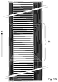
- Fig. 12b shows an arrangement constructed according to this principle, the HF resonator hatching and the additional conductor parts, which are only used to homogenize the B 0 field in the active measuring range are shown in black.
- the superconducting material is distributed fairly homogeneously over the entire area of the RF resonator and the additional conductor parts, which generally also results in a uniform distribution of the dipole moments over the entire area. This even distribution of the dipole moments caused by induced currents in the superconductor creates a practically homogeneous interference field in the measurement volume and can therefore no longer influence the NMR spectrum significantly.
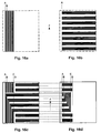
- the entire resonator is preferably made from conductor sections that are as narrow as possible assembled (Fig. 17a), i.e. as narrow as it lithographic manufacturing method allowed, these conductor sections can also be arranged bundled (Fig. 17b, 16c, 16d).
- the bundling of the individual conductor sections can, however, from constructive Reasons still be advantageous, especially when building the capacitive portion of the RF resonator.
- An embodiment of the invention is particularly preferred RF receiving coil arrangement, which is characterized in that all surface elements that differ only in their z position, contain essentially the same amount of superconductor material. Thereby can the surface elements with a simple measure can be easily designed so that the desired RF and magnetic Properties are approximately achieved.
- One if possible fine area division is necessary, however, if the ripple of the interference field in the active measuring range caused by the magnetic Dipole moments of the superconducting material in the individual surface elements is caused to be as small as possible. A reasonable one fine division is obtained when the total number of surface elements is greater than 50, preferably greater than 200.
- this division only depends on the number of the identical surface elements, which can only be identified by their z position distinguish, i.e. lie on strips parallel to the z-axis are oriented. This number should be greater than 20, advantageously be greater than 50.
- An embodiment of the invention is also particularly preferred RF receiving coil arrangement in which the superconducting Conductor structures of the compensation arrangement the RF resonator on both sides by at least half, preferably about twice Extend the extent of the RF resonator in the z direction.
- NMR resonators are mostly used to optimize the fill factor composed of several RF receiver coil arrangements.
- An advantageous embodiment of the invention therefore contains NMR resonator a plurality of coupled RF receiver coil arrangements, preferably 2 or 4, on different partial areas the z-invariant area.
- a particularly simple design of the invention in terms of geometry and production technology results from the fact that the superconductive, inductive and in part also capacitive-acting conductor structures of the RF resonator (s) and the superconductive conductor structures of the compensation arrangement (s) are applied to flat substrate elements which are arranged one below the other and are arranged parallel to the z-axis.
- One embodiment is particularly simple to manufacture the RF receiver coil arrangement according to the invention, in which the superconducting, inductive and sometimes also capacitive conductor structures of the RF resonator and the superconducting conductor structures the associated compensation arrangement arranged in the same plane are.
- This and the previous embodiment work generally optimal if the working point is linear
- the area of the magnetization curve remains, i.e. if the magnetization of the superconductor is not too large.
- ladder structures also work optimally possible outside the linear range.
- An alternative embodiment is characterized in that the superconducting structures of the RF resonator and the associated Compensation arrangement in two or more flat sub-areas lie, which are arranged parallel to each other, being in the first Partial area, the superconductive, inductive and partially capacitive Conductor structures of the RF resonator and parts of the associated superconducting conductor structures of the compensation arrangement, in the remaining parts of the remaining parts of the superconducting Conductor structures of the compensation arrangement are arranged.
- the distances are between the partial areas, measured in a direction perpendicular to the partial areas, maximum 600 ⁇ m, preferably maximum between 50 and 200 ⁇ m. These distances must be kept as small as possible, to minimize errors in the compensation of the magnetism.
- a simple embodiment of the invention is particularly preferred, in which the conductor structures of the compensation arrangement and the RF resonator arranged on the same partial surface of the z-invariant surface are. Starting from this embodiment, a Numerous other embodiments derive from their simple Structure are characterized.
- the invention is at least part of the superconducting sections of the conductor structures in the form of a strip parallel to the axis or perpendicular to the axis arranged to the z direction.
- This embodiment has one simple geometry and serves as a starting point for the production of different Z structures.
- An embodiment allows more scope for variations of the superconducting structures on the z-invariant surfaces different geometric shapes, e.g. out Strips of different orientation and width as well as rectangles, Circles, trapezoids, etc. This results in increased flexibility in the Design of the overall geometry, so that the optimization of error compensation can be achieved even better.
- a very useful Z-structure which can be used one or more times in one inventive RF receiving coil arrangement can be used can consists of identical, narrow superconducting structural elements, those made up of a single conductor or arranged in groups Ladders are built up, which follow one another closely and periodically are arranged continuously in the z-direction, the distance neighboring structural elements small compared to the distance to the The center of the examination volume is.
- the single or multiple used in an RF receiving coil arrangement according to the invention can be made up of structural elements made up of a single Conductors or constructed from conductors arranged in groups, wherein the conductor sections are aligned parallel to the z-axis and are the same or have different distances from each other.
- An alternative embodiment of the Z structure that is single or multiple used in an RF receiving coil arrangement according to the invention is characterized by the fact that it is divided into several preferably rectangular sections are divided, their width is equal to the width of the Z structure, and that these sub-areas pass through straight superconducting strips are filled around a desired one Are inclined to the z-axis, this angle being within a Partial area is either positive or negative, and that the inclined Stripes within a partial area in close succession and are periodically arranged continuously in the z direction, the The distance between adjacent strips is small compared to the distance to Center of the examination volume is and that the inclined strips at the boundary lines between the sub-areas pass.
- the structure of this Z structure is somewhat more complicated, but has the advantage of being on a single surface lies and also provides a perfect compensation if the Superconductor is so strongly magnetized that its working point is outside the linear range of the magnetization curve.
- An embodiment of the invention is particularly preferred RF receiving coil arrangement in which the superconducting conductor structures, that do not belong to the RF resonator, a number of narrow ones Interruptions included across parts or the entire length of each superconducting conductor sections are distributed. So that becomes a significantly better RF decoupling between the RF resonator and the compensation arrangement achieved because the usually arise Eddy currents in the conductor structures through the interruptions are kept particularly low or suppressed.
- the generation of the RF resonator from the desired areas of the Z structures achieved by the fact that within small surface elements Z structures of the superconductor or parts thereof rotated or shifted be, and / or that narrow distances between the conductors superconducting be connected, and / or that narrow interruptions in the Ladders are attached, and / or that oblique and zigzag Z structures are used, and / or that the Z structures can be distributed over two or more partial areas.
- a very specific, particularly preferred embodiment which has a fairly simple geometric structure characterized in that the RF receiver coil arrangement consists of three Z structures is built, namely one on the left and one on the right with vertical and in between one with horizontal straight stripes.
- This embodiment is a bit more complicated in its structure, but has the advantage that it lies on a single surface and then also a perfect one Compensation provides when the superconductor is magnetized so strongly is that its operating point is outside the linear range of the Magnetization curve lies.
- a very precise compensation with many variation options provides another embodiment of the invention in which the whole RF receiving coil arrangement arranged in two levels and off three Z structures is composed, namely from a first and second with parallel to the z-axis and a third with periodic in z and strips arranged transversely to the z axis, the third Z structure above the first two, which are at a certain distance from each other, is positioned and exactly covers it, and the composition of the RF resonator and the compensation structure it happens that the three Z structures are partially disassembled and divided into two separate sub-areas, which belong to one or two substrates, distributed be, the first partial area with the entire RF resonator the main part of the compensation structure, and the second sub-area contains the remainder of the compensation structure, and that the so resulting structures on the two sub-areas in such a way be positioned so that the sum of their structures is equal to that Sum of the original three Z-structures is, and that is a functional NMR resonator is created.
- HTS high-temperature superconductor
- Conductors made of HTS material which are produced in the epitaxial process, have very high critical current densities at very high field strengths in the temperature range from approximately 4.2 K to 30 K, which is generally used in superconducting NMR resonators, and are therefore very suitable for the production of NMR resonators.
- an embodiment of the invention is also advantageous of the superconducting conductor structures from thin, preferably between 0.1 and 1 ⁇ m thick layers are built up, which is within the scope the usual manufacturing technique.
- a superconducting strip which is oriented exactly parallel to the B 0 field and has never been exposed to any other field has only a longitudinal magnetization, as shown in FIG. 7.
- B z components arise only at the two ends of the strip and are negligibly small in the central region of the strip.
- the longitudinal magnetization can be closed by tightly fitting Circuits are shown, which are the thin superconducting Enclose a strip with a rectangular cross-section.
- the length and width of the rectangular cross section is equal to the width b or the thickness w of the strip. Because the thickness w of the superconductor is extremely small (approx. 0.1-1 ⁇ m), the cross-sectional area (bw) is also extremely small and the interference field generated is therefore negligibly small.
- the superconductor had only longitudinal magnetization, one could neglect the magnetization problems in NMR applications. Now, however, with the slightest inclination of the strip in relation to the B 0 field (less than 0.1 degrees are sufficient, since the B 0 field is very strong!), The superconductor generates a transverse magnetization . This can be represented by closed circuits which flow on the surface of the superconducting strip (FIG. 2) and which attempt to compensate for the changed magnetic flux through the superconductor. Incidentally, this compensation only works exactly until the currents in the circuits have each reached the critical current, ie the greatest possible superconducting current in the superconductor.
- the aim of the present invention is therefore to keep the influence of this transverse magnetization on the B 0 homogeneity in the active measuring range as small as possible. So when we talk about the magnetization of the superconductor in the following, we mean the transverse magnetization.
- the NMR spectrum only depends on the B z component in the active measuring range (finding 1) , which originates from the transverse magnetization.
- finding 1 the B z component in the active measuring range
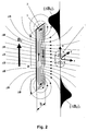
- z components only appear at the two ends of the strip, whereas in the active measuring range they are vanishingly small (Fig. 2).
- the reason for this is the current directions in the closed circuits of the superconductor, which are parallel to the B 0 field in the area of the sample 1, but at the ends of the strip are transverse to the B 0 field.
- currents parallel to the B 0 field do not generate z components and are therefore harmless.
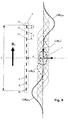
- FIG. 4 shows impressively what would happen if the NMR spectrum were also dependent on the x and y components of the transverse magnetization. It can clearly be seen that there are strong inhomogeneities in the active measuring range 1, which could strongly influence the NMR spectrum. If the NMR would not generously accommodate us due to the weakened requirement that only B z components are to be taken into account, the present invention would be practically impossible to implement.
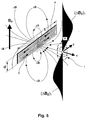
- a superconducting strip which is transverse to the direction of the B 0 field (FIG. 5), basically produces z components, since a large proportion of the currents flow transverse to the direction of the B 0 field. Nevertheless, it is possible to use such strips successfully, as shown by knowledge 4 .
- the only condition is that these strips are periodically repeated continuously in the z direction (FIG. 9c) and that this results in a sufficiently long conductor structure in the z direction. If this is the case, then in the middle area of the conductor structure, ie in the area of the active measuring area, the fields generated by the cross currents and only at the upper and lower ends of the conductor structure compensate for z-components, because there the compensation does not more fully works (Fig. 8).
- a macroscopically homogeneous distribution of the superconducting in the z-direction Parts can be achieved by making the area of the ladder structure in a grid of identical square surface elements is divided, the side length small compared to the distance to The center of the active measuring range is, and the superconductor is on the individual surface elements that are distributed by the superconductor generated transverse magnetization in each surface element magnetic dipoles of the same strength can be replaced.
- conductor structures e.g. from different geometric shapes are composed, e.g. from strips of different Orientation and width as well as from rectangles, circles, Trapezoids, etc, without these conductor structures in the active interference fields Generate measuring range.
- a macroscopically homogeneous distribution of the superconducting in the z-direction Parts can also be achieved by making these parts identical, narrow conductor sections that are close together following and periodically arranged continuously. Doing so the conductor sections follow each other so closely that the waviness of the interference field generated by them is negligible in the active measuring range is small. Examples of such conductor structures are in FIGS. 9c, 9d and 9e shown.
- Z structures In the future, we want to call such ladder structures, as they have just been described, Z structures .
- the present invention is based on a plurality of such Z structures, which are arranged close to one another and / or on top of one another, and builds the desired RF resonator from a specific region of these conductor structures.
- the remaining part of these conductor structures only contributes to the compensation of the magnetism of the superconductor and, ideally, should not carry any HF current.
- HF current should only flow in the HF resonator, and therefore it must be decoupled as well as possible from the other conductors in terms of HF.
- the remaining part of the Z structure which does not belong to the RF resonator, can also be modified in accordance with knowledge 5 , it being possible, for example, to convert vertical conductor arrangements into horizontal configurations, in order to thereby reduce the RF coupling with the RF resonator.
- the first Z structure consists of strips parallel to the B 0 field, followed by a second with strips perpendicular to the B 0 field, and this in turn followed by a third with strips parallel to the B 0 field ,
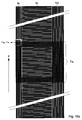
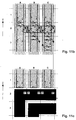
- FIG. 10a An example of this is shown in FIG. 10a, the three Z structures being selected such that an RF resonator of the type FIG. 10a in the patent [6] can be produced therefrom.
- the area of the Z structures from which the RF resonator is to be produced is shown hatched in FIG. 10a (area 7a).
- the predominantly field-producing conductors are produced from the left Z structure 8a, which is closest to the measurement sample, the upper and lower transverse conductors from the middle 9a, and the capacitive components from the right 10a.
- the right conductor structure 10a has twice as many conductors as the left conductor structure 8a, so that the capacitive components can be generated.
- the problem lies in the generation of the corners of the RF resonator, which are located in the conductor structures 8a and 10a (FIG. 10a), and this problem is solved in that certain regions of the individual current paths in the superconductor are closed by small closed current paths S1, S3 , S4, S5 and S6 (Fig. 11 b) are replaced, the currents at the contact lines between adjacent current paths must be opposite in the same way. Since the dimensions of these small current paths meet the requirements of knowledge 5, they may be rotated or shifted within the surface elements A2, B2 and C2 (FIG. 11b) without influencing the B 0 field in the active measuring range. The individual steps that lead to the solution of the problem are described in more detail below.
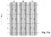
- 11 a is a section of the conductor structure 8 a and consists of three vertical superconducting strips, each with a single one closed current path is shown. This is cut off at the top and bottom, and the direction in which the current flows is with arrows marked.
- the five current paths S1, S3, S4, S5 and S6 each turn clockwise 90 degrees around the center of the corresponding surface element rotated (Fig. 11b), and the same is done with the small current paths performed in the surface elements B3 and C3. Result therefrom current paths with one corner each, as shown in Fig. 11c.
- FIG. 12a After all corners have been generated in accordance with the transformation described, the entire structure of the RF resonator is obtained, as shown in FIG. 12a as a hatched area. This is magnetically practically identical to the brightly marked area in FIG. 10a and therefore does not generate any disturbing B z components in the active measuring range.
- the conductor structure of Fig. 12a has the disadvantage that the RF field lines of the RF resonator, the structure 9a of lying close together have to pierce horizontal stripes and severely hindered because there are only small gaps which the field lines can find their way. Especially the horizontal ones Strips that are enclosed by the RF resonator must let through the greatest concentration of field lines and therefore form the biggest obstacle.
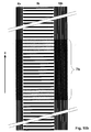
- the middle conductor structure 9a of FIG. 10a was replaced by the more transparent conductor structure 9b of FIG. 10b.
- the structure of FIG. 12b is obtained, which is much more transparent for the RF field lines and therefore has better RF properties.
- a variant is presented in a third embodiment of the inventive idea which does not require rotation or displacement of current paths.
- three Z structures are used.
- the two outer ones are constructed with oblique strips according to FIG. 9f, the middle one with horizontal strips according to FIG. 9c.
- the two outer conductor structures have the advantage that some of the conductors result in a galvanically coherent structure which has an expansion in the z direction and at the same time has connection options at the edges of the two conductor structures at the edges of the two conductor structures. These connection options allow a direct connection to the horizontal strips of the middle conductor structure, and without the current paths having to be rotated or shifted beforehand.
- FIG. 13 An example of this is shown in FIG. 13, the conductor structures being like this were chosen that an NMR resonator of the type Fig. 2c in the patent [8] can be generated.
- the RF resonator has three conductor loops, but not completely closed, but by one narrow distance are interrupted, thereby generating the capacitive Share of the resonator is made possible.
- the first and third The conductor loop has the break in the lower cross conductor, the middle one Ladder loop in the upper cross conductor.
- the big advantage of this third Embodiment is its independence from the anisotropy of the superconductor.
- the two substrates can also be placed one on top of the other that the conductor structures do not come to lie directly on top of each other but are separated by one of the two substrates.
- the substrate that performs the separation function should, if possible be thin so that all conductor structures are practically on one Level.
- an NMR resonator of type 10a in the patent [6] be built.
- three Z structures namely a first and second vertical according to FIG. 14a and a third horizontal 14b, the third being shown separately, actually however lies above the first two and covers them exactly.
- the cross-connections of the RF resonator are derived from the third Z structure (FIG. 14b).
- the width L B of this Z structure is equal to the width L A of the two Z structures from FIG. 14a, ie the three Z structures overlap exactly.
- the three Z-structures are now disassembled and distributed over the two substrates in such a way that no conductors lie on top of one another or intersect on each individual substrate, and that a resonant RF resonator is created overall.
- the first substrate receives the structure of FIG. 15a, ie the RF resonator and the main part of the conductor structures with which the magnetization is compensated, and the second substrate the structure of FIG. 15b with which the remaining part of the magnetization is compensated. It is important that the sum of the structures of FIGS. 15a and 15b is as close as possible to the sum of the Z structures of FIGS. 14a and 14b, because only then is the resonator built on the two substrates magnetically identical to the original three Z- Structures of Figures 14a and 14b, and we know of these that they do not produce B z components in the active measurement range.
- the superconducting conductors that do not belong to the RF resonator can also be provided with narrow interruptions to the To minimize RF coupling with the RF resonator.
- Such interruptions are shown in Fig. 1 for the second embodiment, they can but can also be implemented in all other embodiments, even if they are not explicitly shown there.
Landscapes
- Physics & Mathematics (AREA)
- Condensed Matter Physics & Semiconductors (AREA)
- General Physics & Mathematics (AREA)
- Superconductor Devices And Manufacturing Methods Thereof (AREA)
- Magnetic Resonance Imaging Apparatus (AREA)
Abstract
Description
- Die komplizierten Verfahren ([2], [3], [4]) zur Entmagnetisierung des Supraleiters sind nicht mehr notwendig.
- Externe Störfelder und mechanische Bewegungen des Resonators in Bezug zum statischen Magnetfeld erzeugen zwar eine Magnetisierung im Supraleiter, diese kann jedoch dank der oben erwähnten Kompensation nur einen minimierten Einfluss auf die Homogenität des statischen Magnetfeldes im aktiven Bereich der Messprobe ausüben. Dies gilt auch dann, wenn der Supraleiter sehr stark magnetisiert ist!
- Bereits bekannte Spulenstrukturen [5] lassen sich viel freier und somit wirkungsvoller gestalten.
- Ein transversales Feld soll ein Feld darstellen, das senkrecht zum statischen Magnetfeld B0 orientiert ist, ein longitudinales ein solches, das parallel zu B0 steht.
- Ein NMR-Resonator stellt die komplette Resonator-Anordnung dar. Er setzt sich zusammen aus einer oder mehreren, vorzugsweise 2 oder 4 HF-Empfangsspulenanordnungen, die um das Messvolumen herum angeordnet sind und HF-mäßig miteinander koppeln. Die HF-Empfangsspulenanordnung ihrerseits besteht aus dem HF-Resonator und der Kompensations-Anordnung, wobei der HF-Resonator im Wesentlichen den HF-Strom tragenden Teil der HF-Empfangsspulenanordnung darstellt.
Leiter aus HTS-Material, die im Epitaxialverfahren hergestellt sind, besitzen im Temperaturbereich von ca. 4.2 K bis 30 K, der bei supraleitenden NMR-Resonatoren allgemein verwendet wird, sehr hohe kritische Stromdichten bei sehr hohen Feldstärken und sind deshalb sehr geeignet zur Herstellung von NMR-Resonatoren.
- Fig. 1
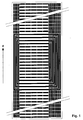
- Zeigt eine modifizierte zweite Ausführungsform des erfindungsgemäßen Resonators. Sie ist praktisch identisch mit der von Fig. 12b, besitzt jedoch in den zusätzlichen Leitern, die der Kompensation der Magnetisierung dienen, schmale Unterbrüche, damit die HF-Kopplung zwischen diesen Leitern und dem eigentlichen HF-Resonator, der schraffiert markiert ist, möglichst klein ist.
- Fig. 2
- Perspektivische Darstellung des Feldes ΔB, das von einem magnetisierten supraleitenden Streifen erzeugt wird, dessen Längsachse parallel zu B0 steht.
- Fig. 3
- Wie Fig. 2 aber in der xz-Ebene dargestellt. Die z-Komponente (ΔBZ)1 des Feldes ΔB ist im Bereich des aktiven Messvolumens praktisch Null und tritt nur am oberen und unteren Rand des Streifens auf.
- Fig. 4
- Feld ΔB der Anordnung von Fig. 2, dargestellt in der xyEbene. Am Ort der aktiven Messprobe 1 sind starke Feldinhomogenitäten vorhanden, die durch die ΔBX- und ΔBY-Komponenten hervorgerufen werden. Diese haben aber keinen Einfluss auf das NMR-Spektrum und können deshalb vernachlässigt werden.
- Fig. 5
- Perspektivische Darstellung des Feldes ΔB, das von einem magnetisierten supraleitenden Streifen erzeugt wird, dessen Längsachse senkrecht zu B0 steht.
- Fig. 6
- Wie Fig. 5, jedoch in der xz-Ebene dargestellt. Die BZ-Komponente (ΔBZ)1 des Feldes ΔB zeigt am Ort der aktiven Messprobe starke Inhomogenitäten, welche die NMR-Resonanzlinien stark beeinflussen können.
- Fig. 7
- Zeigt das Störfeld ΔB, das durch die longitudinale Magnetisierung eines supraleitenden Streifens entsteht, der parallel zum B0-Feld orientiert ist. Störfelder entstehen nur an den beiden Enden des Streifens.
- Fig. 8
- Anordnung aus mehreren supraleitenden Streifen 4a, 4b, 4c, ... ,4k, die auf einer Ebene parallel zu B0 liegen und gleichmäßig übereinander angeordnet sind. Die Bz-Komponente (ΔBz)1 der einzelnen Streifen überlagern sich und erzeugen das Feld (ΔBZ)tot. Dieses ist im Bereich des aktiven Messvolumens 1 praktisch Null, und nur am oberen und unteren Ende der Anordnung sind noch BZ-Komponenten vorhanden.
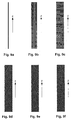
- Fig. 9a
- Supraleitender Streifen parallel zum B0-Feld.
- Fig. 9b
- Supraleitende Leiterstruktur, die aus mehreren, gleichmäßig verteilten Streifen zusammengesetzt ist, die alle parallel zum B0-Feld liegen.
- Fig. 9c
- Supraleitende Leiterstruktur, die aus mehreren, gleichmäßig verteilten Streifen zusammengesetzt ist, die alle senkrecht zum B0-Feld liegen.
- Fig. 9d
- Supraleitende Leiterstruktur, die aus schräg zum B0-Feld liegenden Streifen zusammengesetzt ist.
- Fig. 9e
- Spiegelbild der supraleitenden Leiterstruktur von Fig. 9d.
- Fig. 9f
- Supraleitende Leiterstruktur, die aus Abschnitten der Leiterstrukturen von Fig. 9d und seinem Spiegelbild Fig. 9e zusammengesetzt ist.
- Fig. 10a
- Supraleitende Leiterstruktur, die eine konstante Breite besitzt,
in z-Richtung stark ausgedehnt ist und aus drei Teilstrukturen
aufgebaut ist, zwei senkrechte und eine waagrechte. Mit dem
schraffierten Bereich lässt sich der HF-Resonator aufbauen.
Die übrigen Bereiche dienen der Kompensation der Magnetisierung, die vom HF-Resonator erzeugt wird. - Fig. 10b
- Supraleitende Leiterstruktur wie in Fig. 10a, jedoch mit einer mittleren Teilstruktur, deren horizontale Streifen einen größeren Abstand zueinander haben. Man erreicht damit eine bessere HF-Durchlässigkeit in dieser Teilstruktur.
- Fig. 11a
- Teilausschnitt der Teilstruktur 8a in Fig. 10a. In den drei vertikalen Leiterstreifen ist jeweils ein einzelner geschlossener Strompfad dargestellt, der oben und unten abgeschnitten ist, und dessen Stromrichtung durch Pfeile angegeben ist.
- Fig. 11b
- Zeigt, wie die Stromkreise in den Leiterstreifen in weitere kleinere Stromkreise S1, S3, S4, S5 und S6 unterteilt werden, und wie diese im Uhrzeigersinn um 90 Grad gedreht werden, damit ein Stromkreis mit einer Ecke entsteht.
- Fig. 11c
- Zeigt das Resultat der Transformation von Fig. 11b.
- Fig. 12a
- Zeigt die erste Ausführungsform eines erfindungsgemäßen Resonators, der aus der schraffierten Struktur von Fig. 10a und unter Verwendung der Transformation gemäß Fig. 11b erzeugt wurde. Der Bereich, in dem der HF-Strom fließt, ist schraffiert markiert. Die gesamte Leiterstruktur erzeugt im magnetisierten Zustand praktisch keine z-Komponenteh im aktiven Messbereich!
- Fig. 12b
- Zeigt die zweite Ausführungsform eines erfindungsgemäßen Resonators, der aus der schraffierten Struktur von Fig. 10b und unter Verwendung der Transformation gemäß Fig. 11b erzeugt wurde. Der Bereich, in dem der HF-Strom fließt, ist schraffiert markiert. Die gesamte Leiterstruktur erzeugt im magnetisierten Zustand praktisch keine z-Komponenten im aktiven Messbereich!
- Fig. 13
- Zeigt die dritte Ausführungsform eines erfindungsgemäßen Resonators, der direkt aus den drei senkrechten Teilstrukturen (links, in der Mitte und rechts in Fig. 13) hervorgegangen ist, ohne dass dabei einzelne Leiterteile gedreht oder verschoben werden mussten. Es mussten lediglich einige Leiter über sehr kurze Strecken miteinander verbunden und/oder unterbrochen werden. Der Bereich, in dem der HF-Strom fließt, ist schraffiert markiert. Die gesamte Leiterstruktur erzeugt im magnetisierten Zustand praktisch keine z-Komponenten im aktiven Messbereich!
- Fig. 14a
- Zeigt die beiden senkrechten Leiterstrukturen, aus denen ein Teil der vierten Ausführungsform eines erfindungsgemäßen Resonators hergestellt wird.
- Fig. 14b
- Zeigt die waagrechte Leiterstruktur, aus denen ein Teil der vierten Ausführungsform eines erfindungsgemäßen Resonators hergestellt wird.
- Fig. 15a
- Leiterstruktur auf dem ersten Substrat der vierten Ausführungsform eines erfindungsgemäßen Resonators. Das Substrat enthält den HF-Resonator 7d und den Hauptanteil der Leiterstrukturen, mit denen der Magnetismus kompensiert wird.
- Fig. 15b
- Leiterstruktur auf dem zweiten Substrat der vierten Ausführungsform eines erfindungsgemäßen Resonators. Mit dieser Leiterstruktur wird der Restfehler des Magnetismus kompensiert, der auf dem ersten Substrat aus technischen Gründen nicht kompensiert werden konnte.
- Fig. 16a
- Teilausschnitt aus Fig. 14a. Jeweils drei einzelne Leiter sind zu einem Bündel zusammengefasst und stellen eine der möglichen Ausführungsformen dar.
- Fig. 16b
- Teilausschnitt aus Fig. 14b. Jeweils drei einzelne Leiter sind zu einem Bündel zusammengefasst und stellen eine der möglichen Ausführungsformen dar.
- Fig. 16c
- Teilausschnitt aus Fig. 15a. Jeweils drei einzelne Leiter sind zu einem Bündel zusammengefasst und stellen eine der möglichen Ausführungsformen dar.
- Fig. 16d
- Teilausschnitt aus Fig. 15b. Jeweils drei einzelne Leiter sind zu einem Bündel zusammengefasst und stellen eine der möglichen Ausführungsformen dar.
- Fig. 17a
- Teil eines bevorzugten NMR-Resonators, bei dem die einzelnen Leiter ungebündelt sind. Der schraffierte Bereich gehört zum HF-Resonator.
- Fig. 17b
- Teil eines NMR-Resonators, bei dem drei einzelne Leiter zu einem Bündel zusammengefasst wurden. Der schraffierte Bereich gehört zum HF-Resonator.
Ströme hingegen, die senkrecht zum statischen Magnetfeld gerichtet sind, z.B. solche, die auf einer x-y-Ebene fließen, können BZ-Komponenten erzeugen und müssen deshalb berücksichtigt werden.
- Es sind vielfältige Variationsmöglichkeiten der Leiterstrukturen möglich.
- Alle Leiterstrukturen befindet sich auf einem einzelnen Substrat.
- Wenn eine Anisotropie des Supraleiters vorhanden ist, dann ist eine genaue Kompensation nur im linearen Bereich der Magnetisierungskurve, d.h. nur bei kleinen Störfeldern gewährleistet.
- Die Drehung der kleinen Stromkreise führt zu kleineren Fehlern in den Randbereichen einiger supraleitenden Streifen.
- Die Kompensation ist unabhängig von der Anisotropie des Supraleiters.
- Die gesamte Leiterstruktur befindet sich auf einem einzelnen Substrat.
- Die Variationsmöglichkeiten des Resonators sind beschränkt, weil ein Teil der Leiter eine Zickzack-Struktur mit Anschlussmöglichkeiten an den Rändern der zugehörigen kompensierten Leiterstruktrur besitzen muss.
- Die Kompensation ist unabhängig von der Anisotropie des Supraleiters.
- Es sind vielfältige Variationsmöglichkeiten der Leiterstrukturen möglich.
- Es sind zwei einzelne Substrate oder ein beidseitig beschichtetes Substrat erforderlich, deren Strukturen exakt aufeinander positioniert werden müssen.
- B0
- Statisches Magnetfeld des NMR-Magneten.
- ΔB
- Feld, das durch den magnetisierten Supraleiter erzeugt wird.
- (ΔBZ)1
- z-Komponente von ΔB für einen einzelnen supraleitenden Streifen 2 oder 4.
- (ΔBZ)tot
- z-Komponente von ΔB für die Anordnung 5, die aus mehreren supraleitenden Streifen zusammengesetzt ist.
- S1, S3, S4, S5, S6
- Einzelne geschlossene Strompfade in den supraleitenden Streifen
- 1
- Aktives Messvolumen.
- 2
- Langer, flacher Leiter aus supraleitendem Material (= supraleitender Streifen), dessen Längsachse parallel zu B0 gerichtet ist.
- 3
- Ströme im supraleitenden Streifen 2.
- 4
- Flacher Leiter aus supraleitendem Material (= supraleitender Streifen), dessen Längsachse senkrecht zu B0 gerichtet ist.
- 4a, 4b, 4c, ..., 4k
- Supraleitende Streifen wie unter 4 beschrieben, die zur Anordnung 5 gehören.
- 5
- Anordnung aus mehreren supraleitenden Streifen 4a, 4b, 4c, ... ,4k, die auf einer Ebene parallel zu B0 liegen und gleichmäßig übereinander angeordnet sind.
- 6
- Ströme im supraleitenden Streifen 4.
- 7a, 7b, 7c, 7d
- Bereiche der diversen Resonatoren, in denen sich die Leiterabschnitte befinden, die HF-Ströme tragen. Diese Leiterabschnitte definieren die HF-Resonatoren, d.h. die HF-Resonanzkreise.
- 8a, 8b
- Senkrechte Leiterstruktur parallel zur z-Achse, die teilweise dazu benützt wird, die senkrechten Leiteranteile des Resonators herzustellen, die am nächsten beim Probenvolumen liegen und dort den Hauptanteil des HF-Feldes erzeugen.
- 9a, 9b
- Waagrechte Leiterstruktur senkrecht zur z-Achse, die teilweise dazu benützt wird, um die waagrechten Querverbindungen oben und unten am HF-Resonator herzustellen.
- 10a, 10b
- Senkrechte Leiterstruktur parallel zur z-Achse, die teilweise dazu benützt wird, die kapazitiven Anteile des HF-Resonators herzustellen.
Claims (18)
- HF (= Hochfrequenz)-Empfangsspulenanordnung mit mindestens einem HF-Resonator zum Aussenden und/oder Empfangen von HF-Signalen auf einer oder mehreren gewünschten Resonanzfrequenzen in eine und/oder aus einer Messprobe in einem um einen Koordinatenursprung (x,y,z = 0) angeordneten Untersuchungsvolumen einer NMR-(= Kernspinresonanz)-Apparatur mit einer Einrichtung zur Erzeugung eines homogenen Magnetfelds B0 in Richtung einer z-Achse, wobei zwischen z = -|z1| und z = +|z2| supraleitfähige, induktiv und zum Teil auch kapazitiv wirkende Leiterstrukturen des HF-Resonators im wesentlichen auf einer in z-Richtung translations-invarianten (= z-invarianten) Fläche im radialen (x,y) Abstand von der Messprobe angeordnet sind,
dadurch gekennzeichnet, dass auf der z-invarianten Fläche zusätzlich eine Kompensations-Anordnung vorgesehen ist, die sich mindestens bis zu Werten z < -|z1| -0.5 |r| und z > +|z2| + 0.5 |r| erstreckt, wobei |r| der kleinste vorkommende Abstand zwischen der Messprobe und der Kompensations-Anordnung bedeutet, dass die Kompensations-Anordnung weitere supraleitfähige Leiterstrukturen umfasst, welche HF-mäßig vom HF-Resonator weitgehend entkoppelt sind, dass die Leiterstrukturen der Kompensations-Anordnung und des HF-Resonators ihrerseits aus einzelnen, supraleitende Strukturen enthaltenden Flächenabschnitten (="Z-Strukturen") zusammengesetzt sind, die in der z-invarianten Fläche liegen, jeweils über die ganze Länge in z-Richtung der Leiterstrukturen der Kompensations-Anordnung und des HF-Resonators verlaufen, und deren supraleitende Strukturen so angeordnet sind, dass bei einer geeigneten gedanklichen Zerlegung der Fläche der Z-Strukturen in eine Vielzahl kleiner, gleich großer Flächenelemente und beim gedanklichen Anlegen eines homogenen Testmagnetfeldes entlang der Flächennormalen jedes Flächenelementes für alle Flächenelemente, die sich nur in ihrer z-Position unterscheiden, ein magnetisches Dipolmoment von weitgehend derselben Stärke induziert würde. - HF-Empfangsspulenanordnung nach Anspruch 1, dadurch gekennzeichnet, dass jeweils alle Flächenelemente, die sich nur in ihrer z-Position unterscheiden, im wesentlichen gleich viel Supraleitermaterial enthalten.
- HF-Empfangsspulenanordnung nach einem der vorhergehenden Ansprüche, dadurch gekennzeichnet, dass die supraleitfähigen Leiterstrukturen der Kompensations-Anordnung den HF-Resonator beidseits jeweils um mindestens die halbe, vorzugsweise etwa die zweifache Ausdehnung des HF-Resonators in z-Richtung überragen.
- HF-Empfangsspulenanordnung, die aus mehreren, vorzugsweise 2 oder 4 HF-Empfangsspulenanordnungen nach einem der vorhergehenden Ansprüche aufgebaut ist, wobei diese HF-Empfangsspulenanordnungen miteinander HF-mäßig koppeln und auf unterschiedlichen Teilflächen der z-invarianten Fläche liegen.
- HF-Empfangsspulenanordnung nach einem der vorhergehenden Ansprüche, dadurch gekennzeichnet, dass die supraleitfähigen, induktiv und zum Teil auch kapazitiv wirkenden Leiterstrukturen des oder der HF-Resonatoren und die supraleitfähigen Leiterstrukturen der Kompensations-Anordnung(en) auf ebenen Substratelementen aufgebracht sind, die untereinander und zur z-Achse parallel angeordnet sind.
- HF-Empfangsspulenanordnung nach einem der vorhergehenden Ansprüche, dadurch gekennzeichnet, dass die supraleitfähigen, induktiv und zum Teil auch kapazitiv wirkenden Leiterstrukturen des HF-Resonators und die supraleitfähigen Leiterstrukturen der zugehörigen Kompensations-Anordnung in derselben Ebene angeordnet sind.
- HF-Empfangsspulenanordnung nach einem der Ansprüche 1 bis 5, dadurch gekennzeichnet, dass die supraleitfähigen Strukturen des HF-Resonators und der zugehörigen Kompensationsanordnung in zwei oder mehreren ebenen Teilflächen liegen, die parallel zueinander angeordnet sind, wobei in der ersten Teilfläche die supraleitfähigen, induktiv und zum Teil auch kapazitiv wirkenden Leiterstrukturen des HF-Resonators sowie Teile der zugehörigen supraleitfähigen Leiterstrukturen der Kompensations-Anordnung, in den weiteren Teilflächen die verbleibenden Teile der supraleitfähigen Leiterstrukturen der Kompensations-Anordnung angeordnet sind.
- HF-Empfangsspulenanordnung nach einem der Ansprüche 1 bis 4, ggf. in Verbindung mit Anspruch 7, dadurch gekennzeichnet, dass die supraleitfähigen, induktiv und zum Teil auch kapazitiv wirkenden Leiterstrukturen des oder der HF-Resonatoren und die supraleitfähigen Leiterstrukturen der Kompensations-Anordnung(en) auf flächigen Substratelementen aufgebracht sind, die zylindrisch um die z-Richtung gekrümmt sind.
- HF-Empfangsspulenanordnung nach einem der vorhergehenden Ansprüche, dadurch gekennzeichnet, dass die Leiterstrukturen der Kompensations-Anordnung und des HF-Resonators auf derselben Teilfläche der z-invarianten Fläche angeordnet sind.
- HF-Empfangsspulenanordnung nach einem der vorhergehenden Ansprüche, dadurch gekennzeichnet, dass zumindest ein Teil der supraleitfähigen Abschnitte der Leiterstrukturen streifenförmig achsparallel oder achssenkrecht zur z-Richtung angeordnet ist.
- HF-Empfangsspulenanordnung nach einem der vorhergehenden . Ansprüche, dadurch gekennzeichnet, dass eine oder mehrere ihrer Z-Strukturen aus identischen, schmalen supraleitenden Strukturelementen aufgebaut sind, und diese Strukturelemente aus einem einzelnen Leiter oder in Gruppen angeordneten Leitern bestehen, die eng aufeinander folgend und periodisch kontinuierlich in z-Richtung angeordnet sind, wobei der Abstand benachbarter Strukturelemente klein gegenüber dem Abstand zum Zentrum des Untersuchungsvolumens ist.
- HF-Empfangsspulenanordnung nach einem der vorhergehenden Ansprüche, dadurch gekennzeichnet, dass eine oder mehrere ihrer Z-Strukturen aus Strukturelementen zusammengestellt sind, die aus einem einzelnen Leiter oder in Gruppen angeordneten Leitern bestehen, wobei die Leiterabschnitte parallel zur z-Achse ausgerichtet sind und gleiche oder unterschiedliche Abstände zueinander haben.
- HF-Empfangsspulenanordnung nach einem der Ansprüche 1 bis 10, dadurch gekennzeichnet, dass eine oder mehrere ihrer Z-Strukturen in mehrere, vorzugsweise rechteckige Teilbereiche eingeteilt werden, deren Breite gleich der Breite der jeweiligen Z-Struktur ist, und dass diese Teilbereiche durch gerade supraleitende Streifen gefüllt werden, die um einen gewünschten Winkel zur z-Achse geneigt sind, wobei dieser Winkel innerhalb eines Teilbereiches entweder positiv oder negativ ist, und dass die geneigten Streifen innerhalb eines Teilbereiches eng aufeinander folgend und periodisch kontinuierlich in z-Richtung angeordnet sind, wobei der Abstand benachbarter Streifen klein gegenüber dem Abstand zum Zentrum des Untersuchungsvolumens ist, und dass die geneigten Streifen an den Grenzlinien zwischen den Teilbereichen kontinuierlich ineinander übergehen.
- HF-Empfangsspulenanordnung nach einem der vorhergehenden Ansprüche, dadurch gekennzeichnet, dass die supraleitfähigen Leiterstrukturen, die nicht zum HF-Resonator gehören, eine Anzahl von schmalen Unterbrüchen enthalten, die über Teile oder die ganze Länge der einzelnen supraleitenden Leiterabschnitte verteilt sjnd.
- HF-Empfangsspulenanordnung nach einem der Ansprüche 1 bis 10, dadurch gekennzeichnet, dass die Erzeugung des HF-Resonators aus den gewünschten Bereichen der Z-Strukturen dadurch erreicht wird, dass innerhalb von kleinen Flächenelementen der Z-Strukturen der Supraleiter oder Teile davon gedreht oder verschoben werden, und/oder dass schmale Abstände zwischen den Leitern supraleitend verbunden werden, und/oder dass schmale Unterbrüche in den Leitern angebracht werden, und/oder dass zickzackförmige und schräge Z-Strukturen verwendet werden, und/oder dass die Z-Strukturen auf zwei oder mehreren Teilflächen verteilt werden.
- HF-Empfangsspulenanordnung nach einem der Ansprüche 1 bis 12 oder 14 bis 15, dadurch gekennzeichnet, dass diese aus drei Z-Strukturen aufgebaut ist, nämlich links und rechts je eine mit vertikalen und dazwischen eine mit horizontalen geraden Streifen.
- HF-Empfangsspulenanordnung nach einem der Ansprüche 1 bis 15, dadurch gekennzeichnet, dass diese aus drei Z-Strukturen aufgebaut ist, nämlich links und rechts je eine mit schrägen, teilweise zickzackförmigen, und dazwischen eine mit in z-Richtung periodisch angeordneten Querstreifen.
- HF-Empfangsspulenanordnung nach einem der Ansprüche 1 bis 12 oder 14 bis 15, dadurch gekennzeichnet, dass diese aus drei Z-Strukturen zusammengesetzt ist, nämlich aus einer ersten und zweiten mit parallel zur z-Achse sowie einer dritten mit in z periodisch und quer zur z-Achse angeordneten Streifen, wobei die dritte Z-Struktur über den beiden ersten, die einen bestimmten Abstand zueinander haben, positioniert ist und diese genau überdeckt, und wobei die Zusammensetzung des HF-Resonators und der Kompensationsstruktur dadurch erfolgt, dass die drei Z-Strukturen teilweise zerlegt und auf zwei separaten Teilflächen, die zu einem oder zwei Substraten gehören, verteilt werden, wobei die erste Teilfläche den ganzen HF-Resonator mit dem Hauptanteil der Kompensations-Struktur, und die zweite Teilfläche den Restanteil der Kompensations-Struktur enthält, und dass die so entstandenen Strukturen auf den beiden Teilflächen derart aufeinander positioniert werden, dass die Summe ihrer Strukturen wieder gleich der Summe der ursprünglichen drei Z-Strukturen ist, und dass dadurch ein funktionsfähiger NMR-Resonator entsteht.
Applications Claiming Priority (2)
| Application Number | Priority Date | Filing Date | Title |
|---|---|---|---|
| DE10150131 | 2001-10-11 | ||
| DE10150131A DE10150131C2 (de) | 2001-10-11 | 2001-10-11 | HF-Empfangsspulenanordnung für einen NMR-Resonator mit makroskopisch homogener Verteilung der Leiterstrukturen |
Publications (2)
| Publication Number | Publication Date |
|---|---|
| EP1302780A1 true EP1302780A1 (de) | 2003-04-16 |
| EP1302780B1 EP1302780B1 (de) | 2007-12-12 |
Family
ID=7702137
Family Applications (1)
| Application Number | Title | Priority Date | Filing Date |
|---|---|---|---|
| EP02022542A Expired - Lifetime EP1302780B1 (de) | 2001-10-11 | 2002-10-08 | Supraleitende NMR-Resonatoren mit makroskopisch homogener Verteilung des Supraleiters |
Country Status (4)
| Country | Link |
|---|---|
| US (1) | US6605945B2 (de) |
| EP (1) | EP1302780B1 (de) |
| JP (1) | JP4237465B2 (de) |
| DE (2) | DE10150131C2 (de) |
Cited By (1)
| Publication number | Priority date | Publication date | Assignee | Title |
|---|---|---|---|---|
| EP1331489A3 (de) * | 2002-01-29 | 2005-04-20 | Bruker BioSpin AG | Magnetische Homogenisierung von Supraleitenden HF-Spulen für den Empfang von NMR-Signalen |
Families Citing this family (6)
| Publication number | Priority date | Publication date | Assignee | Title |
|---|---|---|---|---|
| US6335622B1 (en) * | 1992-08-25 | 2002-01-01 | Superconductor Technologies, Inc. | Superconducting control elements for RF antennas |
| DE102004020167B4 (de) * | 2004-04-24 | 2012-01-05 | Bruker Biospin Ag | Hochfrequenz-Resonatorsystem mit optimierter Stromverteilung in den Leiterelementen und Verfahren zu dessen Design |
| CN100592101C (zh) * | 2004-07-29 | 2010-02-24 | 皇家飞利浦电子股份有限公司 | 用于在磁共振成像设备中发射和接收射频磁场的电线圈系统以及具有这种电线圈系统的磁共振成像设备 |
| DE102006052076A1 (de) * | 2006-11-04 | 2008-05-08 | Bruker Biospin Ag | Probenhalter für NMR-Messungen mit Feldhomogenisierung im Probenvolumen durch die Grenzflächen des Probenbehälters |
| JP5904326B2 (ja) * | 2012-01-06 | 2016-04-13 | 日本電子株式会社 | Nmr装置のセットアップ方法 |
| EP3968045B1 (de) | 2020-09-14 | 2025-06-04 | Rohde & Schwarz GmbH & Co. KG | Abbildungssystem und verfahren zur materialcharakterisierung einer probe |
Citations (3)
| Publication number | Priority date | Publication date | Assignee | Title |
|---|---|---|---|---|
| WO1996039636A1 (en) * | 1995-06-05 | 1996-12-12 | Conductus, Inc. | Nuclear magnetic resonance probe coil and method of making same |
| WO1999024845A1 (en) * | 1997-11-07 | 1999-05-20 | Varian, Inc. | Reduction of the effective magnetic susceptibility of superconducting materials in nuclear magnetic resonance (nmr) probes |
| WO1999024821A2 (en) * | 1997-11-07 | 1999-05-20 | Varian, Inc. | Reduction of net magnetic flux trapped in a superconducting nmr rf probe coil |
Family Cites Families (11)
| Publication number | Priority date | Publication date | Assignee | Title |
|---|---|---|---|---|
| US4563648A (en) | 1983-09-22 | 1986-01-07 | Varian Associates, Inc. | Geometric compensation of magnetic susceptibility perturbations in an RF spectrometer |
| DE4101481C2 (de) * | 1991-01-19 | 1994-01-13 | Bruker Analytische Messtechnik | Anordnung zum Kompensieren externer Magnetfeldstörungen bei einem Kernresonanzspektrometer mit supraleitender Magnetspule |
| US5585723A (en) * | 1995-03-23 | 1996-12-17 | Conductus, Inc. | Inductively coupled superconducting coil assembly |
| US5572127A (en) * | 1994-08-29 | 1996-11-05 | Conductus, Inc. | Inhomogeneities in static magnetic fields near superconducting coils |
| DE19733574C2 (de) * | 1997-08-02 | 2000-04-06 | Bruker Ag | Supraleitender Hybrid-Resonator für den Empfang für NMR-Signalen |
| US6646753B2 (en) * | 2000-10-05 | 2003-11-11 | Unaxis, Usa, Inc. | In-situ thickness and refractive index monitoring and control system for thin film deposition |
| US6513451B2 (en) * | 2001-04-20 | 2003-02-04 | Eastman Kodak Company | Controlling the thickness of an organic layer in an organic light-emiting device |
| GB2379735A (en) * | 2001-09-14 | 2003-03-19 | Qinetiq Ltd | Method and apparatus for controlling the growth of thin film during deposition process by measuring the rate of change of optical thickness of the thin-film |
| US7247345B2 (en) * | 2002-03-25 | 2007-07-24 | Ulvac, Inc. | Optical film thickness controlling method and apparatus, dielectric multilayer film and manufacturing apparatus thereof |
| US6879744B2 (en) * | 2003-01-07 | 2005-04-12 | Georgi A. Atanasov | Optical monitoring of thin film deposition |
| US7295330B2 (en) * | 2003-07-11 | 2007-11-13 | Chow Peter P | Film mapping system |
-
2001
- 2001-10-11 DE DE10150131A patent/DE10150131C2/de not_active Expired - Fee Related
-
2002
- 2002-10-03 US US10/262,868 patent/US6605945B2/en not_active Expired - Lifetime
- 2002-10-08 DE DE50211345T patent/DE50211345D1/de not_active Expired - Lifetime
- 2002-10-08 EP EP02022542A patent/EP1302780B1/de not_active Expired - Lifetime
- 2002-10-11 JP JP2002299445A patent/JP4237465B2/ja not_active Expired - Fee Related
Patent Citations (3)
| Publication number | Priority date | Publication date | Assignee | Title |
|---|---|---|---|---|
| WO1996039636A1 (en) * | 1995-06-05 | 1996-12-12 | Conductus, Inc. | Nuclear magnetic resonance probe coil and method of making same |
| WO1999024845A1 (en) * | 1997-11-07 | 1999-05-20 | Varian, Inc. | Reduction of the effective magnetic susceptibility of superconducting materials in nuclear magnetic resonance (nmr) probes |
| WO1999024821A2 (en) * | 1997-11-07 | 1999-05-20 | Varian, Inc. | Reduction of net magnetic flux trapped in a superconducting nmr rf probe coil |
Cited By (1)
| Publication number | Priority date | Publication date | Assignee | Title |
|---|---|---|---|---|
| EP1331489A3 (de) * | 2002-01-29 | 2005-04-20 | Bruker BioSpin AG | Magnetische Homogenisierung von Supraleitenden HF-Spulen für den Empfang von NMR-Signalen |
Also Published As
| Publication number | Publication date |
|---|---|
| US20030071623A1 (en) | 2003-04-17 |
| EP1302780B1 (de) | 2007-12-12 |
| DE50211345D1 (de) | 2008-01-24 |
| DE10150131C2 (de) | 2003-10-09 |
| DE10150131A1 (de) | 2003-04-30 |
| JP2003202367A (ja) | 2003-07-18 |
| US6605945B2 (en) | 2003-08-12 |
| JP4237465B2 (ja) | 2009-03-11 |
Similar Documents
| Publication | Publication Date | Title |
|---|---|---|
| DE10205625C1 (de) | HF-Empfangsspulenanordnung für einen normalleitenden NMR-Resonator mit makroskopisch homogener Verteilung des leitenden Materials | |
| DE102004035851B4 (de) | Resonatorsystem zur Erzeugung eines Hochfrequenz-Magnetfelds | |
| DE10118835C2 (de) | Supraleitende Resonatoren für Anwendungen in der NMR | |
| DE69615180T2 (de) | Sondenspule für die kernspinresonanz | |
| DE69101788T2 (de) | Hochsymmetrischer gleichstrom-squid. | |
| EP0111827B2 (de) | Vorrichtung zur mehrkanaligen Messung schwacher, sich ändernder Magnetfelder und Verfahren zu ihrer Herstellung | |
| EP0223284B1 (de) | Hochfrequenz-Spulenanordnung für Kernspinresonanzgerät | |
| DE19733574C2 (de) | Supraleitender Hybrid-Resonator für den Empfang für NMR-Signalen | |
| DE1764564B2 (de) | Vorrichtung zur erzeugung eines homogenen magnetfeldes | |
| EP1135694A1 (de) | Vorrichtung zur hochauflösenden messung von magnetischen feldern | |
| DE19527921A1 (de) | Doppelseitige HF-Abschirmung für eine Spule in Gradienten-Spulen für Hochgeschwindigkeits MR-Bildgebung | |
| DE69321082T2 (de) | Kernspinresonanzapparat mit einem supraleitenden Magneten | |
| DE10150131C2 (de) | HF-Empfangsspulenanordnung für einen NMR-Resonator mit makroskopisch homogener Verteilung der Leiterstrukturen | |
| DE3918743A1 (de) | Hochfrequenz-quadraturspulenanordnung | |
| EP1746432B1 (de) | HF-Schirm mit reduzierter Kopplung zum HF-Resonatorsystem | |
| EP0689723B1 (de) | Halleffekt-einrichtung mit strom- und hallspannungs-anschlüssen | |
| EP1589347B1 (de) | Hochfrequenz-Resonatorsystem mit optimierter Stromverteilung in den Leiterelementen | |
| DE10041797C2 (de) | Magnetfeldsensitive Dünnfilmsensoreinrichtung mit linearem Sensorelement und Flussantenne | |
| EP1331489A2 (de) | Magnetische Homogenisierung von Supraleitenden HF-Spulen für den Empfang von NMR-Signalen | |
| DE4036841C2 (de) | Mit magnetostatischen Wellen arbeitende Einrichtung | |
| EP0429791B1 (de) | Anordnung zum Abstimmen eines Resonators | |
| EP1387178B1 (de) | SQUID Magnetometer | |
| DE102023132612A1 (de) | Stromüberwachung durch kombination eines shunt-widerstands mit einer rogowski-spule | |
| DE2756714A1 (de) | Schaltungsanordnung zur verstaerkung hochfrequenter, elektromagnetischer wellen | |
| DE102012210815A1 (de) | Magnetische kernresonanzsonde mit schlitz-superleit-spule mit normalmetallüberschicht |
Legal Events
| Date | Code | Title | Description |
|---|---|---|---|
| PUAI | Public reference made under article 153(3) epc to a published international application that has entered the european phase |
Free format text: ORIGINAL CODE: 0009012 |
|
| 17P | Request for examination filed |
Effective date: 20030214 |
|
| AK | Designated contracting states |
Designated state(s): AT BE BG CH CY CZ DE DK EE ES FI FR GB GR IE IT LI LU MC NL PT SE SK TR |
|
| AX | Request for extension of the european patent |
Extension state: AL LT LV MK RO SI |
|
| AKX | Designation fees paid |
Designated state(s): CH DE FR GB LI |
|
| GRAP | Despatch of communication of intention to grant a patent |
Free format text: ORIGINAL CODE: EPIDOSNIGR1 |
|
| GRAS | Grant fee paid |
Free format text: ORIGINAL CODE: EPIDOSNIGR3 |
|
| GRAA | (expected) grant |
Free format text: ORIGINAL CODE: 0009210 |
|
| AK | Designated contracting states |
Kind code of ref document: B1 Designated state(s): CH DE FR GB LI |
|
| REG | Reference to a national code |
Ref country code: GB Ref legal event code: FG4D Free format text: NOT ENGLISH |
|
| REG | Reference to a national code |
Ref country code: CH Ref legal event code: EP |
|
| REF | Corresponds to: |
Ref document number: 50211345 Country of ref document: DE Date of ref document: 20080124 Kind code of ref document: P |
|
| GBT | Gb: translation of ep patent filed (gb section 77(6)(a)/1977) |
Effective date: 20080303 |
|
| ET | Fr: translation filed | ||
| PLBE | No opposition filed within time limit |
Free format text: ORIGINAL CODE: 0009261 |
|
| STAA | Information on the status of an ep patent application or granted ep patent |
Free format text: STATUS: NO OPPOSITION FILED WITHIN TIME LIMIT |
|
| 26N | No opposition filed |
Effective date: 20080915 |
|
| REG | Reference to a national code |
Ref country code: FR Ref legal event code: PLFP Year of fee payment: 14 |
|
| REG | Reference to a national code |
Ref country code: FR Ref legal event code: PLFP Year of fee payment: 15 |
|
| REG | Reference to a national code |
Ref country code: FR Ref legal event code: PLFP Year of fee payment: 16 |
|
| REG | Reference to a national code |
Ref country code: FR Ref legal event code: PLFP Year of fee payment: 17 |
|
| PGFP | Annual fee paid to national office [announced via postgrant information from national office to epo] |
Ref country code: DE Payment date: 20181024 Year of fee payment: 17 |
|
| PGFP | Annual fee paid to national office [announced via postgrant information from national office to epo] |
Ref country code: FR Payment date: 20181023 Year of fee payment: 17 Ref country code: CH Payment date: 20181025 Year of fee payment: 17 Ref country code: GB Payment date: 20181025 Year of fee payment: 17 |
|
| REG | Reference to a national code |
Ref country code: DE Ref legal event code: R119 Ref document number: 50211345 Country of ref document: DE |
|
| REG | Reference to a national code |
Ref country code: CH Ref legal event code: PL |
|
| PG25 | Lapsed in a contracting state [announced via postgrant information from national office to epo] |
Ref country code: LI Free format text: LAPSE BECAUSE OF NON-PAYMENT OF DUE FEES Effective date: 20191031 Ref country code: CH Free format text: LAPSE BECAUSE OF NON-PAYMENT OF DUE FEES Effective date: 20191031 Ref country code: DE Free format text: LAPSE BECAUSE OF NON-PAYMENT OF DUE FEES Effective date: 20200501 |
|
| GBPC | Gb: european patent ceased through non-payment of renewal fee |
Effective date: 20191008 |
|
| PG25 | Lapsed in a contracting state [announced via postgrant information from national office to epo] |
Ref country code: GB Free format text: LAPSE BECAUSE OF NON-PAYMENT OF DUE FEES Effective date: 20191008 Ref country code: FR Free format text: LAPSE BECAUSE OF NON-PAYMENT OF DUE FEES Effective date: 20191031 |