EP1302733B1 - Soupape de détente - Google Patents
Soupape de détente Download PDFInfo
- Publication number
- EP1302733B1 EP1302733B1 EP02022926A EP02022926A EP1302733B1 EP 1302733 B1 EP1302733 B1 EP 1302733B1 EP 02022926 A EP02022926 A EP 02022926A EP 02022926 A EP02022926 A EP 02022926A EP 1302733 B1 EP1302733 B1 EP 1302733B1
- Authority
- EP
- European Patent Office
- Prior art keywords
- pressure sensor
- refrigerant
- expansion valve
- pressure
- valve
- Prior art date
- Legal status (The legal status is an assumption and is not a legal conclusion. Google has not performed a legal analysis and makes no representation as to the accuracy of the status listed.)
- Expired - Lifetime
Links
Images

Classifications
-
- F—MECHANICAL ENGINEERING; LIGHTING; HEATING; WEAPONS; BLASTING
- F25—REFRIGERATION OR COOLING; COMBINED HEATING AND REFRIGERATION SYSTEMS; HEAT PUMP SYSTEMS; MANUFACTURE OR STORAGE OF ICE; LIQUEFACTION SOLIDIFICATION OF GASES
- F25B—REFRIGERATION MACHINES, PLANTS OR SYSTEMS; COMBINED HEATING AND REFRIGERATION SYSTEMS; HEAT PUMP SYSTEMS
- F25B41/00—Fluid-circulation arrangements
- F25B41/30—Expansion means; Dispositions thereof
- F25B41/31—Expansion valves
- F25B41/33—Expansion valves with the valve member being actuated by the fluid pressure, e.g. by the pressure of the refrigerant
- F25B41/335—Expansion valves with the valve member being actuated by the fluid pressure, e.g. by the pressure of the refrigerant via diaphragms
-
- F—MECHANICAL ENGINEERING; LIGHTING; HEATING; WEAPONS; BLASTING
- F25—REFRIGERATION OR COOLING; COMBINED HEATING AND REFRIGERATION SYSTEMS; HEAT PUMP SYSTEMS; MANUFACTURE OR STORAGE OF ICE; LIQUEFACTION SOLIDIFICATION OF GASES
- F25B—REFRIGERATION MACHINES, PLANTS OR SYSTEMS; COMBINED HEATING AND REFRIGERATION SYSTEMS; HEAT PUMP SYSTEMS
- F25B2341/00—Details of ejectors not being used as compression device; Details of flow restrictors or expansion valves
- F25B2341/06—Details of flow restrictors or expansion valves
- F25B2341/068—Expansion valves combined with a sensor
- F25B2341/0683—Expansion valves combined with a sensor the sensor is disposed in the suction line and influenced by the temperature or the pressure of the suction gas
-
- F—MECHANICAL ENGINEERING; LIGHTING; HEATING; WEAPONS; BLASTING
- F25—REFRIGERATION OR COOLING; COMBINED HEATING AND REFRIGERATION SYSTEMS; HEAT PUMP SYSTEMS; MANUFACTURE OR STORAGE OF ICE; LIQUEFACTION SOLIDIFICATION OF GASES
- F25B—REFRIGERATION MACHINES, PLANTS OR SYSTEMS; COMBINED HEATING AND REFRIGERATION SYSTEMS; HEAT PUMP SYSTEMS
- F25B2700/00—Sensing or detecting of parameters; Sensors therefor
- F25B2700/19—Pressures
- F25B2700/191—Pressures near an expansion valve
Definitions
- This invention relates to an expansion valve, according to the preamble part of claim 1.
- Such a valve is known from EP-A-1 055 888.
- a known box-shaped expansion valve has a valve portion for adiabatically expanding high-pressure refrigerant introduced therein to deliver the same to an evaporator, and a refrigerant passage for allowing refrigerant from the evaporator to pass therethrough, formed in the same body block, and includes a power element for sensing the temperature and pressure of the refrigerant at an outlet port of the evaporator.
- the expansion valve of this type is generally configured such that a valve element of the valve portion is urged by the power element for sensing the temperature and pressure of refrigerant at the outlet port of the evaporator to thereby control a valve travel of the valve.
- a refrigeration cycle conventionally is equipped with a pressure switch or a pressure sensor for detecting the pressure of the refrigerant with a view to performing optimum cooling and heating operations.
- the pressure switch or the pressure sensor conventionally is attached by a joint to a refrigerant piping.
- a plurality of components are being integrally modularised to simplify the whole construction of the refrigeration cycle. This results in limited locations in the refrigeration cycle where the pressure switch or the pressure sensor can be freely attached.
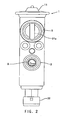
- Fig. 3 shows a conventional expansion valve provided with the pressure sensor 22.
- a valve element 8 for controlling the flow rate of refrigerant is urged in a valve-closing direction by a compression coil spring 9 which is arranged within an opening 2a formed in the body block 2 such that the opening 2a has one end open to the outside air.
- the compression coil spring 9 has a fixed end thereof received by an adjusting screw 10 screwed into an interior thread 2b formed in an inner wall of the opening 2a.
- the adjusting screw 10 and the thread 2b define a compression spring load adjustment device.
- a set value at which the valve element 8 of the expansion valve starts to open is adjusted by adjusting the amount of screwing of the adjusting screw 10 to change the urging force or preload of the compression coil spring 9.
- the pressure sensor 22 is fixed at an open end-side portion of the opening 2a by a securing ring, for detecting the pressure of refrigerant within a high-pressure refrigerant passage.
- a sealing O-ring 22e mounted between the pressure sensor 22 and the opening 2a.
- the adjusting screw 10 and the pressure sensor 22 are sequentially mounted in the opening 2a. Therefore, the assembly work of the expansion valve is troublesome and parts cost cannot be reduced.
- the structural length of the body block 2 is undesirably large, because the pressure sensor 22 and the adjustment screw 10 are positioned one behind the other.
- An object of the invention is to provide an expansion valve including a pressure sensor which enables reduction of parts cost and facilitates assembly work.
- the present invention provides an expansion valve, the integrated pressure sensor of which receives a fixed end of the compression coil spring on a side opposite to the valve element, for sensing pressure of the introduced high-pressure refrigerant, such that the compression coil spring load is adjusted by the amount of screwing the pressure sensor into the opening of the body back.
- the pressure sensor simultaneously serves as spring receiving means for the compression coil spring urging the valve element in a direction of seating the valve element.
- the load of the compression coil spring is changed according to the amount of screwing of the pressure sensor into the opening of the body block, so as to adjust the set value at which the valve element of the expansion valve starts to open. This makes it possible to dispense with a member for adjusting the load of the compression coil spring, which contributes to reduction of parts cost.
- the pressure sensor integrated into the expansion valve simultaneously serves as a spring load adjusting device and a spring end retainer, respectively.
- An expansion valve 1 serves for adiabatically expanding refrigerant while controlling the flow rate of the refrigerant delivered to an evaporator, not shown.
- the expansion valve 1 is part of a not shown refrigeration cycle also including a compressor, a condenser, a liquid receiver, the evaporator, and so forth.
- the refrigeration cycle is used as an automotive air conditioner, for instance.
- the expansion valve 1 in Figs. 1 and 2 has a body block 2 having a side portion formed with a connection hole 3 to which is connected a high-pressure refrigerant piping to receive a high-temperature and high-pressure refrigerant from a not shown liquid receiver through the piping, and a side portion formed with a connection hole 4 to which is connected a low-pressure refrigerant piping to supply a low-temperature and low-pressure refrigerant expanded by the expansion vale 1 to the evaporator.
- connection hole 5 to which is connected a refrigerant piping extending from an outlet port of the evaporator, and the connection hole 5 is communicated with a connection hole 6 connected to a refrigerant piping extending to the compressor.
- Holes 5, 6 define a second passage of the body block 2.
- a first passage is provided between holes 3, 4 for adiabatically expanding high-pressure refrigerant introduced therein to deliver the same to the evaporator.
- the second passage allows the refrigerant from the evaporator to pass therethrough.
- Both passages are formed in the same body block 2 in parallel with each other.
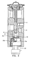
- the body block 2 has a through hole 19 formed therein in a manner such that the through hole 19 extends perpendicularly to the above passages.
- a valve seat 7 is formed in the shape of a constriction of the passage at a midpoint of the same in which the passage area is reduced.
- a ball valve element 9 is arranged in a manner opposed to the valve seat 7 from the upstream side.
- the narrowest portion of a gap between the valve element 8 and an inlet portion of the valve seat 7 forms a variable orifice for reducing the flow of the high-pressure liquid refrigerant, where the high-pressure liquid refrigerant is adiabatically expanded and flows into a downstream-side passage leading to the connection hole 4. Further, in an opening 2a extending downward from the first passage on the side of the connection hole 3, there is arranged a compression coil spring 9 urging the valve element 9 in a direction of seating the valve element 9 on the valve seat 7.
- the power element 11 comprises an upper housing 12 and a lower housing 13, made of metal, a diaphragm 14 formed by a flexible thin metal plate and arranged in a manner dividing a space surrounded by the upper and lower housings, and a diaphragm-receiving board 15.
- the temperature-sensing chamber 16 is sealed by a metal ball 17.
- the diaphragm-receiving board 15 arranged on an underside of the diaphragm 14 is in abutment with the upper end portion of a rod 19 such that displacement of the diaphragm 14 is transmitted to the valve element 8 via the rod 18.
- the rod 18 is inserted into the through hole 19 formed in the body block 2 and has the upper end portion thereof held by a holding member 21.
- the through hole 19 has a large-diameter portion 19a at an upper portion thereof, and a small-diameter portion 19b at a lower portion thereof,
- the large-diameter portion 19a receives an O-ring 20 arranged therein for sealing a gap between the rod 18 and the through hole 19.
- the holding member 21 includes a hollow cylindrical portion 21a extending downward in a manner crossing the second passage communicating between the connection holes 5, 6, and has a lower end portion thereof fitted in the large-diameter portion 19a of the through hole 19.
- the hollow cylindrical portion 21a restricts the upward movement of the O-ring 20 by an end surface of the lower end portion thereof, and the O-ring 20 prevents bypass leakage of the refrigerant from the high-pressure side to the low-pressure side, via the through hole 19.
- the holding member 21 contains a spring 21 b for giving a lateral load to the rod 18.
- the spring 21 b controls the movement of the rod 18 so as to inhibit occurrence of longitudinal vibration of the rod 18.
- the opening 2a arranged in a lower portion of the body block 2 has a pressure sensor 22 fitted therein.
- the pressure sensor 22 is comprised of a diaphragm member 22a forming a pressure-sensing portion, a connector member 22b for extracting a signal indicative of a pressure sensed by the pressure-sensing portion therefrom, and a holding member 22c for holding the diaphragm member 22a on the connector member 22b.
- the holding member 22c is shaped like a shell and has a central recessed portion 26 integrally formed around a protrusion 22d for positioning the centre of a fixed end of the compression coil spring 9.
- the holding member 22c is engaged by an exterior thread portion 24 with the body block 2 at a screw portion 23 formed in a lower portion of body block hole 2a.
- the holding member 22c has an exterior groove 25 receiving an O-ring 22e for sealing a space containing the valve element 8 and the atmosphere from each other.
- the groove 25 holds the O-ring 22e in sliding sealing contact with the smooth inner cylindrical wall of hole 2a.
- the load of the compression coil spring 9 is directly set by the pressure sensor 22 which is screwed into the opening 2a of the body block 2 from outside.
- the load of the compression coil spring 9 can be adjusted by adjusting the amount of screwing of the pressure sensor 22 into the opening 2a at the screw portion 23, i.e. by varying the thread-in depth of the pressure sensor 22.
- the pressure sensor 22 and the hole 2a with the interior threaded portion 23 are designed in axial direction and in relation to each other such that the thread-in depth of the pressure sensor 22 may be varied within a sufficiently large axial range in order to allow necessary, gradual variations of the spring load without jeopardising the sealed positioning of the pressure sensor 22 in the body block 2.
- the expansion valve 1 is configured such that the pressure sensor 22 is screwed into an opening communicating with a space into which high-pressure refrigerant is introduced. This configuration facilitates the assembly work of the pressure sensor and the expansion valve.
- the pressure sensor serves as a spring load adjusting screw, it is possible to dispense with the adjusting screw, which reduces parts cost.
- the length of the body block 2 can be markedly reduced, whereby the accuracy of cutting the valve in the longitudinal direction can be enhanced.
Landscapes
- Physics & Mathematics (AREA)
- Engineering & Computer Science (AREA)
- Fluid Mechanics (AREA)
- Mechanical Engineering (AREA)
- Thermal Sciences (AREA)
- General Engineering & Computer Science (AREA)
- Temperature-Responsive Valves (AREA)
- Safety Valves (AREA)
- Air-Conditioning For Vehicles (AREA)
Claims (7)
- Soupape de détente (1) qui comprend un premier passage (3, 4) destiné à détendre de manière adiabatique un fluide frigorifique sous haute pression introduit en elle, afin de fournir le fluide frigorifique à un évaporateur, et un second passage (5, 6) au travers duquel passe un fluide frigorifique en provenance de l'évaporateur, formés dans le même bloc de corps (2), comprenant :un élément de soupape (8) aménagé de manière à être opposé à un siège de soupape (7) formé dans une partie intermédiaire du premier passage (3, 4) ;un élément de puissance (11) destiné à pousser l'élément de soupape (8) dans des directions vers et hors du siège de soupape (7) en fonction d'une température et d'une pression du fluide frigorifique présent dans le second passage (5, 6) ;un ressort à boudin de compression (9) destiné à pousser l'élément de soupape (8) vers le siège de soupape (7) ;caractérisée par :un capteur de pression (22) qui est vissé à l'intérieur d'une ouverture (2a, 23) du bloc de corps (2) afin de détecter une pression du fluide frigorifique introduit sous haute pression, l'ouverture (2a, 23) étant formée de manière à communiquer avec un côté du premier passage (3, 4) dans lequel le fluide frigorifique sous haute pression est introduit, de telle sorte que le capteur de pression (22) reçoit une extrémité fixe du ressort à boudin de compression (9) sur un côté opposé à l'élément de soupape (8), dans lequel le ressort à boudin de compression (9) a une charge réglée par une valeur de vissage du capteur de pression (22) à l'intérieur de l'ouverture (2a, 23).
- Soupape de détente selon la revendication 1, caractérisée en ce que le ressort de compression (9) est pré-chargé vers l'élément de soupape (8) grâce à un dispositif de réglage de charge de ressort de compression, et en ce que le capteur de pression (22) définit le dispositif de réglage de charge de ressort de compression de la soupape de détente (1).
- Soupape de détente selon la revendication 1 ou la revendication 2, caractérisée en ce que le capteur de pression (22) comprend une section externe filetée (24), et en ce que la section externe filetée (24) est vissée à l'intérieur d'une partie interne filetée (23) du bloc de corps (2).
- Soupape de détente selon la revendication 1 ou la revendication 2 caractérisée en ce que l'ouverture (2a) et la partie interne filetée (23) sont toutes deux aménagées de manière coaxiale dans une partie inférieure de bloc de corps et sont conçues avec des extensions axiales respectives plus longues qu'une plage de réglage de charge de ressort de compression nécessaire au seul positionnement du capteur de pression (22) dans une condition fixe et étanche dans le bloc de corps (2).
- Soupape de détente selon au moins l'une des revendications précédentes, caractérisée en ce que l'ouverture de bloc de corps (2a) comprend une paroi interne de contact en douceur avec une bague d'étanchéité cylindrique, en ce que le capteur de pression (22) comprend un élément de maintien en forme de coque (22c) comportant une partie cylindrique ayant un diamètre externe qui s'adapte essentiellement avec le diamètre interne de la paroi interne de contact avec la bague d'étanchéité, et en ce que la partie cylindrique de l'élément de maintien (22c) est formé avec au moins une gorge de circonférence (25) destinée à recevoir un joint torique (22e).
- Soupape de détente selon au moins l'une des revendications précédentes, caractérisée en ce que le capteur de pression (22) comprend une saillie (22d) destinée à positionner le centre du ressort de compression (9) et une partie (26) destinée à recevoir l'extrémité fixe du ressort à boudin de compression (9).
- Soupape de détente selon la revendication 6, caractérisée en ce que la partie (26) destinée à recevoir l'extrémité fixe de ressort est formée en une partie en retrait qui entoure la saillie (22d).
Applications Claiming Priority (2)
| Application Number | Priority Date | Filing Date | Title |
|---|---|---|---|
| JP2001312450A JP3949417B2 (ja) | 2001-10-10 | 2001-10-10 | 膨張弁 |
| JP2001312450 | 2001-10-10 |
Publications (2)
| Publication Number | Publication Date |
|---|---|
| EP1302733A1 EP1302733A1 (fr) | 2003-04-16 |
| EP1302733B1 true EP1302733B1 (fr) | 2006-12-13 |
Family
ID=19131103
Family Applications (1)
| Application Number | Title | Priority Date | Filing Date |
|---|---|---|---|
| EP02022926A Expired - Lifetime EP1302733B1 (fr) | 2001-10-10 | 2002-10-10 | Soupape de détente |
Country Status (4)
| Country | Link |
|---|---|
| US (1) | US6612503B2 (fr) |
| EP (1) | EP1302733B1 (fr) |
| JP (1) | JP3949417B2 (fr) |
| DE (1) | DE60216695T2 (fr) |
Families Citing this family (14)
| Publication number | Priority date | Publication date | Assignee | Title |
|---|---|---|---|---|
| JP2004270975A (ja) * | 2003-03-06 | 2004-09-30 | Tgk Co Ltd | 流量制御弁 |
| FR2862745B1 (fr) * | 2003-11-25 | 2007-01-05 | Valeo Climatisation | Organe de detente a electronique integree pour boucle a fluide refrigerant, en particulier d'un appareil de climatisation pour habitacle de vehicule |
| DE102005050086A1 (de) * | 2004-11-08 | 2006-05-11 | Otto Egelhof Gmbh & Co. Kg | Expansionsventil, insbesondere für eine Kältemittelanlage |
| EP1666817A3 (fr) * | 2004-12-01 | 2007-01-17 | Fujikoki Corporation | Vanne de régulation de pression |
| JP2008533431A (ja) * | 2005-03-18 | 2008-08-21 | キャリア・コマーシャル・リフリージレーション・インコーポレーテッド | 増加圧力逃がし弁を備えた遷臨界冷凍 |
| JP2008076031A (ja) * | 2006-09-25 | 2008-04-03 | Denso Corp | 膨張弁 |
| EP2177847A1 (fr) * | 2008-10-16 | 2010-04-21 | Valeo Systemes Thermiques | Dispositif à vanne d'extension thermostatique pour circuit hydraulique réfrigérant |
| JP2010145027A (ja) * | 2008-12-19 | 2010-07-01 | Fuji Koki Corp | 膨張弁及び冷凍サイクル |
| JP5501670B2 (ja) * | 2009-06-23 | 2014-05-28 | 株式会社不二工機 | ダイアフラム式流体制御弁 |
| JP5743744B2 (ja) * | 2011-06-24 | 2015-07-01 | 株式会社不二工機 | ダイアフラム式流体制御弁 |
| JP6182363B2 (ja) * | 2013-06-07 | 2017-08-16 | 株式会社不二工機 | 膨張弁 |
| WO2016199610A1 (fr) * | 2015-06-09 | 2016-12-15 | 株式会社デンソー | Soupape de réduction de pression |
| CN111503344A (zh) * | 2019-01-30 | 2020-08-07 | 杭州三花研究院有限公司 | 阀组件 |
| EP4298387A1 (fr) | 2021-05-05 | 2024-01-03 | Parker-Hannifin Corporation | Détendeur thermique sans ampoule |
Family Cites Families (7)
| Publication number | Priority date | Publication date | Assignee | Title |
|---|---|---|---|---|
| US3667247A (en) | 1970-07-10 | 1972-06-06 | Controls Co Of America | Refrigeration system with evaporator outlet control valve |
| DE3823449A1 (de) | 1988-07-11 | 1990-01-18 | Bosch Gmbh Robert | Messeinrichtung zur erfassung des drucks und der temperatur |
| US5068503A (en) | 1989-04-11 | 1991-11-26 | Hans Sladky | High-pressure sensor for fluid conditions and method and apparatus using same |
| US6105379A (en) * | 1994-08-25 | 2000-08-22 | Altech Controls Corporation | Self-adjusting valve |
| JPH11325661A (ja) | 1998-05-21 | 1999-11-26 | Fujikoki Corp | 膨張弁 |
| JP2001050617A (ja) | 1999-05-28 | 2001-02-23 | Fuji Koki Corp | 膨張弁 |
| JP2001133081A (ja) | 1999-11-09 | 2001-05-18 | Tgk Co Ltd | 膨張弁 |
-
2001
- 2001-10-10 JP JP2001312450A patent/JP3949417B2/ja not_active Expired - Fee Related
-
2002
- 2002-10-03 US US10/263,915 patent/US6612503B2/en not_active Expired - Fee Related
- 2002-10-10 EP EP02022926A patent/EP1302733B1/fr not_active Expired - Lifetime
- 2002-10-10 DE DE60216695T patent/DE60216695T2/de not_active Expired - Fee Related
Also Published As
| Publication number | Publication date |
|---|---|
| EP1302733A1 (fr) | 2003-04-16 |
| US6612503B2 (en) | 2003-09-02 |
| DE60216695T2 (de) | 2007-04-12 |
| JP3949417B2 (ja) | 2007-07-25 |
| JP2003121030A (ja) | 2003-04-23 |
| US20030066303A1 (en) | 2003-04-10 |
| DE60216695D1 (de) | 2007-01-25 |
Similar Documents
| Publication | Publication Date | Title |
|---|---|---|
| EP1302733B1 (fr) | Soupape de détente | |
| US7624930B2 (en) | Temperature-type expansion valve | |
| EP1052463B1 (fr) | Robinet détendeur | |
| US20070283717A1 (en) | Expansion valve | |
| EP2573489B1 (fr) | Vanne d'expansion | |
| US5642858A (en) | Thermal expansion valve | |
| EP0829690B1 (fr) | Vanne de détente | |
| EP1052464B1 (fr) | Robinet détendeur thermique | |
| EP1308660B1 (fr) | Vanne de détente | |
| JPH10288424A (ja) | 温度式膨張弁 | |
| EP1209426B1 (fr) | Robinet détendeur | |
| US5238219A (en) | Thermostatic expansion valve | |
| KR19990082706A (ko) | 팽창밸브 | |
| JPH08152232A (ja) | 膨張弁 | |
| KR20050011715A (ko) | 팽창 밸브 | |
| CN111043798A (zh) | 温度式膨胀阀、以及具备温度式膨胀阀的冷冻循环系统 | |
| JP3920059B2 (ja) | 膨張弁 | |
| JP3996429B2 (ja) | 膨張弁 | |
| US6776351B2 (en) | Expansion valve | |
| JP4043195B2 (ja) | 膨張弁 | |
| US20030014989A1 (en) | Expansion valve unit | |
| JP4743926B2 (ja) | 膨張弁 | |
| CN214534664U (zh) | 阀装置 | |
| JP2002350015A (ja) | 膨張弁およびその取付構造 | |
| JP3920056B2 (ja) | 膨張弁 |
Legal Events
| Date | Code | Title | Description |
|---|---|---|---|
| PUAI | Public reference made under article 153(3) epc to a published international application that has entered the european phase |
Free format text: ORIGINAL CODE: 0009012 |
|
| 17P | Request for examination filed |
Effective date: 20030210 |
|
| AK | Designated contracting states |
Designated state(s): AT BE BG CH CY CZ DE DK EE ES FI FR GB GR IE IT LI LU MC NL PT SE SK TR |
|
| AX | Request for extension of the european patent |
Extension state: AL LT LV MK RO SI |
|
| AKX | Designation fees paid |
Designated state(s): DE ES FR GB IT |
|
| GRAP | Despatch of communication of intention to grant a patent |
Free format text: ORIGINAL CODE: EPIDOSNIGR1 |
|
| GRAS | Grant fee paid |
Free format text: ORIGINAL CODE: EPIDOSNIGR3 |
|
| GRAA | (expected) grant |
Free format text: ORIGINAL CODE: 0009210 |
|
| AK | Designated contracting states |
Kind code of ref document: B1 Designated state(s): DE ES FR GB IT |
|
| PG25 | Lapsed in a contracting state [announced via postgrant information from national office to epo] |
Ref country code: IT Free format text: LAPSE BECAUSE OF FAILURE TO SUBMIT A TRANSLATION OF THE DESCRIPTION OR TO PAY THE FEE WITHIN THE PRESCRIBED TIME-LIMIT;WARNING: LAPSES OF ITALIAN PATENTS WITH EFFECTIVE DATE BEFORE 2007 MAY HAVE OCCURRED AT ANY TIME BEFORE 2007. THE CORRECT EFFECTIVE DATE MAY BE DIFFERENT FROM THE ONE RECORDED. Effective date: 20061213 |
|
| REG | Reference to a national code |
Ref country code: GB Ref legal event code: FG4D |
|
| REF | Corresponds to: |
Ref document number: 60216695 Country of ref document: DE Date of ref document: 20070125 Kind code of ref document: P |
|
| PG25 | Lapsed in a contracting state [announced via postgrant information from national office to epo] |
Ref country code: ES Free format text: LAPSE BECAUSE OF FAILURE TO SUBMIT A TRANSLATION OF THE DESCRIPTION OR TO PAY THE FEE WITHIN THE PRESCRIBED TIME-LIMIT Effective date: 20070324 |
|
| ET | Fr: translation filed | ||
| PLBE | No opposition filed within time limit |
Free format text: ORIGINAL CODE: 0009261 |
|
| STAA | Information on the status of an ep patent application or granted ep patent |
Free format text: STATUS: NO OPPOSITION FILED WITHIN TIME LIMIT |
|
| 26N | No opposition filed |
Effective date: 20070914 |
|
| GBPC | Gb: european patent ceased through non-payment of renewal fee |
Effective date: 20071010 |
|
| PG25 | Lapsed in a contracting state [announced via postgrant information from national office to epo] |
Ref country code: GB Free format text: LAPSE BECAUSE OF NON-PAYMENT OF DUE FEES Effective date: 20071010 |
|
| PGFP | Annual fee paid to national office [announced via postgrant information from national office to epo] |
Ref country code: DE Payment date: 20081127 Year of fee payment: 7 |
|
| PGFP | Annual fee paid to national office [announced via postgrant information from national office to epo] |
Ref country code: FR Payment date: 20081024 Year of fee payment: 7 |
|
| REG | Reference to a national code |
Ref country code: FR Ref legal event code: ST Effective date: 20100630 |
|
| PG25 | Lapsed in a contracting state [announced via postgrant information from national office to epo] |
Ref country code: FR Free format text: LAPSE BECAUSE OF NON-PAYMENT OF DUE FEES Effective date: 20091102 Ref country code: DE Free format text: LAPSE BECAUSE OF NON-PAYMENT OF DUE FEES Effective date: 20100501 |