EP1302291A1 - Grinding device for resin composition - Google Patents
Grinding device for resin composition Download PDFInfo
- Publication number
- EP1302291A1 EP1302291A1 EP00940821A EP00940821A EP1302291A1 EP 1302291 A1 EP1302291 A1 EP 1302291A1 EP 00940821 A EP00940821 A EP 00940821A EP 00940821 A EP00940821 A EP 00940821A EP 1302291 A1 EP1302291 A1 EP 1302291A1
- Authority
- EP
- European Patent Office
- Prior art keywords
- powders
- granulated
- resin composition
- resin
- rotor
- Prior art date
- Legal status (The legal status is an assumption and is not a legal conclusion. Google has not performed a legal analysis and makes no representation as to the accuracy of the status listed.)
- Withdrawn
Links
Images


Classifications
-
- B—PERFORMING OPERATIONS; TRANSPORTING
- B01—PHYSICAL OR CHEMICAL PROCESSES OR APPARATUS IN GENERAL
- B01J—CHEMICAL OR PHYSICAL PROCESSES, e.g. CATALYSIS OR COLLOID CHEMISTRY; THEIR RELEVANT APPARATUS
- B01J2/00—Processes or devices for granulating materials, e.g. fertilisers in general; Rendering particulate materials free flowing in general, e.g. making them hydrophobic
- B01J2/20—Processes or devices for granulating materials, e.g. fertilisers in general; Rendering particulate materials free flowing in general, e.g. making them hydrophobic by expressing the material, e.g. through sieves and fragmenting the extruded length
-
- B—PERFORMING OPERATIONS; TRANSPORTING
- B29—WORKING OF PLASTICS; WORKING OF SUBSTANCES IN A PLASTIC STATE IN GENERAL
- B29B—PREPARATION OR PRETREATMENT OF THE MATERIAL TO BE SHAPED; MAKING GRANULES OR PREFORMS; RECOVERY OF PLASTICS OR OTHER CONSTITUENTS OF WASTE MATERIAL CONTAINING PLASTICS
- B29B9/00—Making granules
- B29B9/10—Making granules by moulding the material, i.e. treating it in the molten state
-
- B—PERFORMING OPERATIONS; TRANSPORTING
- B29—WORKING OF PLASTICS; WORKING OF SUBSTANCES IN A PLASTIC STATE IN GENERAL
- B29B—PREPARATION OR PRETREATMENT OF THE MATERIAL TO BE SHAPED; MAKING GRANULES OR PREFORMS; RECOVERY OF PLASTICS OR OTHER CONSTITUENTS OF WASTE MATERIAL CONTAINING PLASTICS
- B29B9/00—Making granules
- B29B9/12—Making granules characterised by structure or composition
- B29B2009/125—Micropellets, microgranules, microparticles
Definitions
- the present invention relates to a granulating apparatus of a resin composition, and more particularly to a granulating apparatus of a resin composition which has a reduced amount of fine powders generated at a time of a pulverizing step and can reduces a pulverizing time.
- an epoxy resin powder coating material is generally produced in accordance with a dry process by melting and mixing respective raw materials and cooling and pulverizing the raw materials.
- a cooling belt is mainly used for cooling.
- a pulverizing efficiency is reduced, and further in some cases, a target particle diameter can not be obtained.
- a pulverizer, a victory mill, a ball mill, a jet mill and the like are employed for pulverization, and these are selectively employed in accordance with a nature of the powder and a target particle diameter.
- the pulverization is separately performed in a coarse pulverizing step of pulverizing to a size of 5 to 15 mm and a pulverizing step of pulverizing to a target particle diameter.
- a producing method with respect to an improvement of a pulverizing efficiency is disclosed in Japanese Patent Unexamined Publication Nos. 8-218643 and 8-294916. By employing this method, it is possible to reduce an amount of generated fine powders more than the conventional fine pulverizing step using the coarse pulverizing step such as a hammer mill or the like.
- the resin is cooled and becomes a high viscosity during the granulating operation in some nature of the resin, so that a clogging is generated, whereby not only a deterioration of characteristic is generated but also a size of an obtained product is uneven and larger than the target particle diameter even in the case of being granulated.
- a pin type disc when the supplied resin has a low melting viscosity and is continuously supplied to a rotor linearly, the resin is extended between two adjacent pins due to a centrifugal force so as to become a fiber shape, so that a length of the fiber becomes longer than a distance between the pins.
- the resin is supplied to a local pin. Accordingly, the resin is excessively supplied in a local manner and the resin is extruded from a whole of a hollow portion of the pin, the resin forms an uneven shape and a significantly large shape. This can be applied to a vane type disc in the same manner. That is, this method is insufficient to stably obtain the granulating operation which can reduce the pulverizing time.
- a container for collecting the granulated powder is structured such that an outer tank is arranged in a vertical direction to a flying direction of granulated powders or a fiber-like resin composition.
- a wall surface receives an impact energy corresponding to a velocity energy of the granulated powders without being reduced, the granulated powders are easily attached to the wall surface.
- the granulated powders are attached to the wall surface, the granulated powders are further molten and attached to each other on the basis of those granulated powders, so that the granulated powders are hard to be cooled, thereby promoting a deterioration due to a heat.
- Japanese Patent Unexamined Publication No. 11-309713 As a structure of aiming to provide a granulating apparatus of a resin composition for solving the problems mentioned above, there is listed up Japanese Patent Unexamined Publication No. 11-309713. However, there is a case that the granulated powders immediately collected within an outer tank or in a container from the outer tank are cooled at a time of flying in an outer peripheral portion but keep heat in an inner portion. Then, there is a case that the granulated powders are molten and attached to each other and a characteristic is deteriorated in the case of accumulating the granulated powders mentioned above.
- An object of the present invention is to provide a granulating apparatus of a pulverized coating material which can reduce a pulverizing time by stably obtaining granulated powders having a particle diameter closer to a target product particle diameter with generating no deterioration of a characteristic, and can reduce a number of classifying steps and save labor and time by reducing a generating amount of fined powders and coarse powders in the pulverizing step.
- a granulating apparatus of a resin composition comprising:
- a molten and mixed resin composition in accordance with the present invention corresponds to a resin composition having a thermosetting resin such as an epoxy resin, an epoxy-polyester resin, a polyester resin, an acrylic-polyester resin, a polyimide resin or the like or a thermoplastic resin such as a polyvinyl chloride, a polyethylene resin, a polyamide resin, an ABS resin, a fluorocarbon resin or the like as a base resin, and containing various kinds of raw materials such as a curing agent, a filler, a pigment or the other additive mixed thereto in accordance with a usage, and the base resin may be a modified resin or a mixture in accordance with a usage.
- a thermosetting resin such as an epoxy resin, an epoxy-polyester resin, a polyester resin, an acrylic-polyester resin, a polyimide resin or the like or a thermoplastic resin such as a polyvinyl chloride, a polyethylene resin, a polyamide resin, an ABS resin, a fluor
- An apparatus in accordance with the present invention is structured such that in a granulating apparatus of a resin composition which can heat a punching metal net or a magnetic material contact therewith by electrically connecting an alternating current power source to a rotor provided with the punching metal net and a magnetizing coil placed near the magnetic material, thereby uniformly heating the punching metal net, the punching metal net made of a magnetic material on an outer periphery thereof or having small holes made of a nonmagnetic material and being contact with a magnetic material, fine powders or fiber-like materials can be easily obtained by supplying the molten and mixed resin composition from an opening portion through a double-pipe type cylinder body placed in an upper portion of a rotating rotor, bringing the resin composition into contact with the heated punching metal net and passing the resin composition through the small holes due to a centrifugal force without increasing a melting viscosity of the resin due to hardening.
- an outer tank for recovering the granulated powder is formed in a double cone shape provided with a cooling jacket, an incline in an upper cone portion prevents the granulated powders from being attached and the rotor rotates on the lower cone portion, whereby the granulated powders drop down along a generated air stream, it is possible to effectively cool the granulated powders.
- a discharge port for taking out the granulated powders is provided in the lower cone portion of the double-cone shaped outer tank and an air feeding apparatus having a rotary blade mounted in a middle of a pipe passage provided in front thereof is connected, the transferred granulated powders are brought into contact with the rotating rotary blade while being cooled by an air, thereby being crushed into powders having a particle size close to a particle size of a final product in comparison with the powders immediately after being granulated which are output from the metal net of the rotor at a time of collecting in the product recovery container.
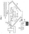
- Fig. 1 is a schematic view for realizing a milling method of a resin composition in accordance with the present invention
- Fig. 2 shows a rotor and a magnetizing coil
- Fig. 3 shows a cylinder body placed in an upper portion of the rotor.
- the resin molten and mixed in a twin screw extruder 9 is supplied to a rotor 1 through a cylinder body 5 cooled by passing a refrigerant between an inner wall and an outer wall.
- a material of the cylinder body is not particularly limited as far as the cylinder body can be cooled through the refrigerant, for example, an iron, an aluminum or the like can be listed up.
- the rotor 1 is connected to a motor 10 and can be rotated at an optional rotational speed.
- a punching metal net 2 placed on an outer periphery of the rotor 1, having a uniform hole diameter and made of a magnetic material is heated due to an eddy current loss and a hysteresis loss caused by a passage of an alternate magnetic flux generated by electrically supplying an alternating power source generated by an alternating power source generating apparatus 6 to a magnetizing coil 4 provided near the punching metal net 2.
- the magnetic material for example, an iron material, a silicone steel or the like can be listed up, and one kind or two or more kinds of magnetic material can be combined and used.
- the punching metal net is not limited to the magnetic material, and a nonmagnetic material can be employed.
- an upper portion and/or a lower portion of the punching metal net may be contact with the magnetic material, or may be coated with the magnetic material.
- the punching metal net is heated by the heated magnetic material 3 corresponding to a heat source in accordance with a heat conduction.
- the punching metal net 2 is made of the nonmagnetic material having a high heat conductivity, it is possible to significantly uniformly heat.
- the nonmagnetic material for example, a copper, an aluminum or the like can be listed up, and one or two or more nonmagnetic materials can be combined and used.
- the resin flies and moves to the punching metal net 2 heated due to the centrifugal force after being supplied to the rotor 1.
- the resin being contact with the heated punching metal net 2 easily passes through the holes in the punching metal net 2 and is discharged without a melting viscosity being increased due to hardening.
- the temperature for heating can be optionally set in accordance with the characteristic of the applied resin.
- the thermosetting resin when excessively increasing the heating temperature, there is a case that the hardening of the resin is promoted, the characteristic is deteriorated and the clogging is generated in the holes of the punching metal net 2.
- the contact time is short and a significantly little influence is given to the characteristic.
- the punching metal net 2 is uniformly heated, a significantly little change of the characteristic is locally given.
- the resin composition granulated in powders or in a fiber shape by passing through the holes in the punching metal net 2 is collected in the outer tank 8 placed in the periphery of the rotor 1.
- the outer tank 8 is formed in a double cone shape, and an upper cone portion is inclined at 10 to 80 degrees, preferably at 25 to 65 degrees with respect to the collision surface in order to prevent the granulated powders from being attached to the inner wall or the granulated powders from being molten and attached to each other. In the case that the incline is too small, it is not sufficiently disperse the collision energy of the granulated powders and an attachment to the wall surface is generated.
- An air stream is generated within the outer tank 8 due to the rotation of the rotor 1, however, in order to further strengthen the air stream, one or a plurality of air stream generating apparatuses 14 can be mounted and commonly used.
- the air stream generating apparatus 14 is not limited as far as the apparatus can forcibly generate the air stream such as a blower, a compressed air or the like.
- the size of the outer tank-8 is dependent upon an amount of resin to be treated, and for example, in the case that a diameter of the rotor is 20 cm, it is possible to prevent the granulated powders from being attached and being molten and attached when the inner diameter is 100 cm.
- a discharge port for taking out the granulated powders is provided in the lower cone portion of the double-cone shaped outer tank 8 and is connected to an air feeding apparatus 12 having a rotary blade 11 mounted in the middle of a pipe passage provided in front thereof.
- the transferred milled powders are brought into contact with the rotating rotary blade 11 while being air cooled, thereby being crushed into powders having a particle size closer to that of a final product than that of powders immediately after being granulated and flying out from the metal net of the rotor. Accordingly, a specific surface area is large, whereby a cooling operation is promoted, so that the granulated powders are transferred to a granulated powder recovery container 13 after being sufficiently cooled.
- the collision energy between the granulated powders and the rotary blade 11 is sufficiently smaller than a crushing energy of a normal pulverizer, no fine powders are generated by the collision with the rotary blade 11.
- the material and the number of vanes and the number of the rotary blade 11 are not limited as far as the rotary blade 11 generates the pulverization at a time of being brought into contact with the granulated powders.
- a fan or a blower of the air feeding apparatus can be mounted in front of the granulated powder recovery container 13 in place of the rotary blade.
- an average breadth of the collected powders or fiber-like granulated powders is adjusted to 0.5 ⁇ to 12.0 ⁇ , and. an average length is adjusted to 1.0 ⁇ to 20.0 ⁇ .
- the average breadth and the average length of granulated powder are adjusted in accordance with a supply speed of a molten resin composition, a melting viscosity, a rotational speed of the rotor, a hole diameter of the punching metal net, and a heating temperature.
- the average breadth of the granulated powders 1.0 ⁇ to 20.0 ⁇ and the average length thereof 1.0 ⁇ to 40.0 ⁇ which is obtained in the conventional art Japanese Patent Unexamined Publication No. 11-309713, the granulated powders having the particle diameter close to the particle diameter of the product powders can be obtained, so that an effect of reducing the fined powders and the coarse powders generated in the pulverizing step is increased.
- This epoxy resin composition is supplied to a rotor provided with a copper punching metal net having a hole diameter of 1.0 mm and heated to 120°C by a magnetizing coil, having a diameter of 24 cm and rotating at. 3000 r.p.m, whereby a fiber-like composition having an average breadth 90 ⁇ m and an average length 134 ⁇ m is obtained.
- a pulverizer at 4000 r.p.m, an epoxy resin composition of an average particle diameter 50 ⁇ m including no fine powders having a particle size equal to or less than 7 ⁇ m and no coarse powders having a particle size equal to or more than 170 ⁇ m is obtained.
- the same molten epoxy resin composition having a temperature of 120°C as that of the embodiment 1 is supplied to a rotor provided with a copper punching metal net having a hole diameter of 3.0 mm and heated to 120°C by a magnetizing coil, having a diameter of 24 cm and rotating at 3000 r.p.m, whereby a fiber-like composition having an average breadth 100 ⁇ m and an average length 150 ⁇ m is obtained.
- a pulverizer at 4000 r.p.m., an epoxy resin composition of an average particle diameter 60 ⁇ m including no fine powders having a particle size equal to or less than 10 ⁇ m and no coarse powders having a particle size equal to or more than 180 ⁇ m is obtained.
- an epoxy resin composition of an average particle diameter 70 ⁇ m including 11 wt% of fine powders having a particle size equal to or less than 10 ⁇ m and 8% of coarse powders having a particle size equal to or more-than 180 ⁇ m is obtained.
- the granulating apparatus of the resin composition of the present invention since it is possible to stably obtain the granulated fine powders having the small particle diameter close to the target particle diameter of the product and having the narrow particle size distribution, it is possible to reduce the pulverizing time, it is possible to reduce the generation of the fine powders and the coarse powders in the pulverizing step and it is possible to improve a productivity together with the omission and reduction of the classifying step or the saving of labor and time and improve an operation environment.
- the granulating apparatus it is possible to connect the granulating apparatus to a desired granulated powder processing apparatus so as to intend to obtain an automation and it is possible to completely seal the granulating apparatus so as to prevent the powders and dusts from giving a bad influence to a human body and an environment.
Landscapes
- Chemical & Material Sciences (AREA)
- Organic Chemistry (AREA)
- Chemical Kinetics & Catalysis (AREA)
- Engineering & Computer Science (AREA)
- Mechanical Engineering (AREA)
- Processing And Handling Of Plastics And Other Materials For Molding In General (AREA)
- Crushing And Grinding (AREA)
Abstract
Description
Claims (3)
- A granulating apparatus of a resin composition comprising:wherein a discharge port for taking out the granulated powders is provided in a lower portion of the outer tank, and the granulated powder is transferred from the outer tank while being air cooled by an air feeding apparatus provided in front of the discharge port.a cylinder body placed in an upper portion of a rotating rotor;an opening portion for supplying a resin composition molten and mixed through the cylinder body;a punching metal net having small holes on an outer periphery of the rotor;heating means;the small holes on the punching metal net being evenly heated passing the resin composition therethrough due to a centrifugal force so as to granulate the resin composition into fined powders or a fiber shape;an outer tank recovering the granulated resin and having a wall surface of a granulated powder collision portion inclined at a degree between 10 and 80 degrees; anda cooling jacket provided on an outer periphery of the outer tank,
- A granulating apparatus of a resin composition as claimed in claim 1, wherein the outer tank for recovering the granulated powder is formed in double cone shape, and the granulated powders drop down on a lower cone portion provided with a cooling jacket in an outer periphery thereof along an air stream generated by a rotation of the rotor after the granulated powders are brought into contact with an upper cone portion provided with a cooling jacket in an outer periphery thereof, whereby the granulated powders can be cooled.
- A granulating apparatus of a resin composition as claimed in claim 1 or 2, wherein a discharge port provided in a lower portion of the outer tank is connected to an air feeding apparatus having a rotary blade mounted in a pipe passage.
Applications Claiming Priority (1)
| Application Number | Priority Date | Filing Date | Title |
|---|---|---|---|
| PCT/JP2000/004134 WO2001098046A1 (en) | 2000-06-23 | 2000-06-23 | Grinding device for resin composition |
Publications (2)
| Publication Number | Publication Date |
|---|---|
| EP1302291A1 true EP1302291A1 (en) | 2003-04-16 |
| EP1302291A4 EP1302291A4 (en) | 2004-03-17 |
Family
ID=11736175
Family Applications (1)
| Application Number | Title | Priority Date | Filing Date |
|---|---|---|---|
| EP00940821A Withdrawn EP1302291A4 (en) | 2000-06-23 | 2000-06-23 | Grinding device for resin composition |
Country Status (6)
| Country | Link |
|---|---|
| US (1) | US6631861B1 (en) |
| EP (1) | EP1302291A4 (en) |
| KR (1) | KR20020025224A (en) |
| CN (1) | CN1317114C (en) |
| CA (1) | CA2381062A1 (en) |
| WO (1) | WO2001098046A1 (en) |
Cited By (1)
| Publication number | Priority date | Publication date | Assignee | Title |
|---|---|---|---|---|
| CN112295648A (en) * | 2020-10-30 | 2021-02-02 | 广东磊蒙重型机械制造有限公司 | A jaw crusher with a filtering and screening structure and a method of using the same |
Families Citing this family (7)
| Publication number | Priority date | Publication date | Assignee | Title |
|---|---|---|---|---|
| DE202007014782U1 (en) * | 2007-10-23 | 2009-03-05 | Rieter Automatik Gmbh | Stranggranulierungsvorrichtung |
| CN107617736A (en) * | 2017-09-08 | 2018-01-23 | 张家港创博金属科技有限公司 | Metal-resin composite pellets preparation method and device |
| ES2961981T3 (en) | 2017-09-18 | 2024-03-14 | Int Paper Co | Method and apparatus for controlling a fiber fractionation system |
| CN109731537A (en) * | 2018-12-31 | 2019-05-10 | 江苏麒祥高新材料有限公司 | A kind of complexes of binder resin processing |
| CN112354480B (en) * | 2020-11-23 | 2022-12-27 | 浙江省耕地质量与肥料管理总站 | Granulation equipment is used in soil fertilizer production |
| CN113426369B (en) * | 2021-07-28 | 2022-06-21 | 山东奇立伟肥业股份有限公司 | Novel spraying cup for chemical fertilizer maker |
| CN114768976B (en) * | 2022-05-22 | 2023-07-25 | 山东太岳建筑装饰材料有限公司 | Comprehensive production line and process of environmental protection wall covering |
Family Cites Families (15)
| Publication number | Priority date | Publication date | Assignee | Title |
|---|---|---|---|---|
| US3700177A (en) * | 1971-05-13 | 1972-10-24 | Cypro Inc | Comminuting apparatus |
| JPS50121529A (en) | 1974-03-15 | 1975-09-23 | ||
| JPS5722898B2 (en) | 1974-03-15 | 1982-05-15 | ||
| US3979073A (en) * | 1975-04-03 | 1976-09-07 | Wheelabrator-Frye, Inc. | Method and apparatus for conditioning granular material |
| JPS59203448A (en) | 1983-04-08 | 1984-11-17 | Meiji Seika Kaisha Ltd | Production unit for spun sugar |
| JP2840642B2 (en) * | 1991-08-02 | 1998-12-24 | ダイセル・ヒュルス株式会社 | Resin granulation method and apparatus |
| JPH08218643A (en) | 1995-02-17 | 1996-08-27 | Sadao Yamamoto | Method of placing mortar and cover sheet used therefor |
| JP3274311B2 (en) * | 1995-04-11 | 2002-04-15 | 住友ベークライト株式会社 | Powder coating manufacturing method |
| JP3337861B2 (en) * | 1995-04-27 | 2002-10-28 | 住友ベークライト株式会社 | Method for producing fine-particle thermosetting resin |
| JPH1032581A (en) | 1996-07-16 | 1998-02-03 | Matsushita Electric Ind Co Ltd | ATM cell switch |
| JP3056076B2 (en) | 1996-07-16 | 2000-06-26 | 日本電気株式会社 | ATM cell switching equipment |
| JPH1032582A (en) | 1996-07-16 | 1998-02-03 | Fujitsu Ltd | Line switching unit for cell switch |
| JP3695683B2 (en) * | 1998-02-16 | 2005-09-14 | 住友ベークライト株式会社 | Resin composition milling equipment |
| JP3625256B2 (en) * | 1998-02-16 | 2005-03-02 | 住友ベークライト株式会社 | Resin composition milling equipment |
| JP3695689B2 (en) * | 2000-03-17 | 2005-09-14 | 住友ベークライト株式会社 | Resin composition milling equipment |
-
2000
- 2000-06-23 US US10/069,230 patent/US6631861B1/en not_active Expired - Fee Related
- 2000-06-23 WO PCT/JP2000/004134 patent/WO2001098046A1/en not_active Ceased
- 2000-06-23 CN CNB008119252A patent/CN1317114C/en not_active Expired - Lifetime
- 2000-06-23 CA CA002381062A patent/CA2381062A1/en not_active Abandoned
- 2000-06-23 EP EP00940821A patent/EP1302291A4/en not_active Withdrawn
- 2000-06-23 KR KR1020027002049A patent/KR20020025224A/en not_active Withdrawn
Cited By (2)
| Publication number | Priority date | Publication date | Assignee | Title |
|---|---|---|---|---|
| CN112295648A (en) * | 2020-10-30 | 2021-02-02 | 广东磊蒙重型机械制造有限公司 | A jaw crusher with a filtering and screening structure and a method of using the same |
| CN112295648B (en) * | 2020-10-30 | 2022-06-10 | 广东磊蒙重型机械制造有限公司 | Jaw crusher with filtering and screening structure and using method |
Also Published As
| Publication number | Publication date |
|---|---|
| CA2381062A1 (en) | 2001-12-27 |
| CN1317114C (en) | 2007-05-23 |
| EP1302291A4 (en) | 2004-03-17 |
| US6631861B1 (en) | 2003-10-14 |
| WO2001098046A1 (en) | 2001-12-27 |
| CN1370106A (en) | 2002-09-18 |
| KR20020025224A (en) | 2002-04-03 |
Similar Documents
| Publication | Publication Date | Title |
|---|---|---|
| JP3139721B2 (en) | Fluidized bed jet mill | |
| US6631861B1 (en) | Grinding device for resin composition | |
| JP4205888B2 (en) | Powder processing apparatus and powder processing method | |
| JP4891574B2 (en) | Crusher and powder manufacturing method using the crusher | |
| CN1042013C (en) | Method for manufacturing thermoplastic synthetic resin impalpabale powder and apparatus for the same | |
| JP4805473B2 (en) | Fine grinding device and powder product manufacturing system | |
| JP3625256B2 (en) | Resin composition milling equipment | |
| JP3695689B2 (en) | Resin composition milling equipment | |
| JP4291685B2 (en) | Toner production method | |
| JPH0816795B2 (en) | Toner manufacturing method and apparatus | |
| JP3695683B2 (en) | Resin composition milling equipment | |
| CN107722799B (en) | Production process for improving production yield of powder coating | |
| JP3556075B2 (en) | Powder coating manufacturing method | |
| JP2967859B2 (en) | Manufacturing method of composite powder | |
| JP3695686B2 (en) | Granulator for thermosetting resin composition | |
| JP4579671B2 (en) | Production method of finely crushed rubber | |
| JP3337861B2 (en) | Method for producing fine-particle thermosetting resin | |
| JPH10338518A (en) | Production of calcium carbonate | |
| JPH08281643A (en) | Preparation of powder paint | |
| JPH06262096A (en) | Preparation of toner for static charge image development and grinding device | |
| JP2002326038A (en) | Crusher for toner production | |
| JPS59196754A (en) | Finely crushing apparatus | |
| JP2002273250A (en) | Toner production system | |
| CN121178278A (en) | A grinder for making squid ink powder and its grinding method | |
| JP2003285319A (en) | Milling apparatus for resin composition and milling method using the same |
Legal Events
| Date | Code | Title | Description |
|---|---|---|---|
| PUAI | Public reference made under article 153(3) epc to a published international application that has entered the european phase |
Free format text: ORIGINAL CODE: 0009012 |
|
| 17P | Request for examination filed |
Effective date: 20020221 |
|
| AK | Designated contracting states |
Designated state(s): AT BE CH CY DE DK ES FI FR GB GR IE IT LI LU MC NL PT SE |
|
| A4 | Supplementary search report drawn up and despatched |
Effective date: 20040204 |
|
| RIC1 | Information provided on ipc code assigned before grant |
Ipc: 7B 29B 9/06 B Ipc: 7B 01J 2/20 B Ipc: 7B 02C 19/12 A |
|
| RBV | Designated contracting states (corrected) |
Designated state(s): AT BE DE IT |
|
| 17Q | First examination report despatched |
Effective date: 20050311 |
|
| STAA | Information on the status of an ep patent application or granted ep patent |
Free format text: STATUS: THE APPLICATION IS DEEMED TO BE WITHDRAWN |
|
| 18D | Application deemed to be withdrawn |
Effective date: 20050722 |