EP1302272A1 - An ultrasonic welding tip and apparatus with this tip - Google Patents
An ultrasonic welding tip and apparatus with this tip Download PDFInfo
- Publication number
- EP1302272A1 EP1302272A1 EP02102336A EP02102336A EP1302272A1 EP 1302272 A1 EP1302272 A1 EP 1302272A1 EP 02102336 A EP02102336 A EP 02102336A EP 02102336 A EP02102336 A EP 02102336A EP 1302272 A1 EP1302272 A1 EP 1302272A1
- Authority
- EP
- European Patent Office
- Prior art keywords
- tip
- sonotrode
- grooves
- anvil
- workpiece
- Prior art date
- Legal status (The legal status is an assumption and is not a legal conclusion. Google has not performed a legal analysis and makes no representation as to the accuracy of the status listed.)
- Granted
Links
- 238000003466 welding Methods 0.000 title claims abstract description 40
- 230000007423 decrease Effects 0.000 claims abstract description 7
- 239000000463 material Substances 0.000 claims description 22
- 238000000576 coating method Methods 0.000 claims description 12
- WFKWXMTUELFFGS-UHFFFAOYSA-N tungsten Chemical compound [W] WFKWXMTUELFFGS-UHFFFAOYSA-N 0.000 claims description 11
- 229910052721 tungsten Inorganic materials 0.000 claims description 11
- 239000010937 tungsten Substances 0.000 claims description 11
- 239000011248 coating agent Substances 0.000 claims description 8
- 238000000034 method Methods 0.000 abstract description 12
- 229910052782 aluminium Inorganic materials 0.000 description 7
- XAGFODPZIPBFFR-UHFFFAOYSA-N aluminium Chemical compound [Al] XAGFODPZIPBFFR-UHFFFAOYSA-N 0.000 description 7
- 235000014676 Phragmites communis Nutrition 0.000 description 5
- XLYOFNOQVPJJNP-UHFFFAOYSA-N water Substances O XLYOFNOQVPJJNP-UHFFFAOYSA-N 0.000 description 5
- VYZAMTAEIAYCRO-UHFFFAOYSA-N Chromium Chemical compound [Cr] VYZAMTAEIAYCRO-UHFFFAOYSA-N 0.000 description 4
- 229910052804 chromium Inorganic materials 0.000 description 4
- 239000011651 chromium Substances 0.000 description 4
- ATJFFYVFTNAWJD-UHFFFAOYSA-N Tin Chemical compound [Sn] ATJFFYVFTNAWJD-UHFFFAOYSA-N 0.000 description 3
- 230000002093 peripheral effect Effects 0.000 description 3
- 238000004381 surface treatment Methods 0.000 description 3
- PXHVJJICTQNCMI-UHFFFAOYSA-N Nickel Chemical compound [Ni] PXHVJJICTQNCMI-UHFFFAOYSA-N 0.000 description 2
- WUPRCGRRQUZFAB-DEGKJRJSSA-N corrin Chemical compound N1C2CC\C1=C\C(CC/1)=N\C\1=C/C(CC\1)=N/C/1=C\C1=NC2CC1 WUPRCGRRQUZFAB-DEGKJRJSSA-N 0.000 description 2
- 229910052751 metal Inorganic materials 0.000 description 2
- 239000002184 metal Substances 0.000 description 2
- 230000004048 modification Effects 0.000 description 2
- 238000012986 modification Methods 0.000 description 2
- 229910001311 M2 high speed steel Inorganic materials 0.000 description 1
- 229910000725 T1 high speed steel Inorganic materials 0.000 description 1
- 238000010521 absorption reaction Methods 0.000 description 1
- PNEYBMLMFCGWSK-UHFFFAOYSA-N aluminium oxide Inorganic materials [O-2].[O-2].[O-2].[Al+3].[Al+3] PNEYBMLMFCGWSK-UHFFFAOYSA-N 0.000 description 1
- 229910052593 corundum Inorganic materials 0.000 description 1
- 238000005336 cracking Methods 0.000 description 1
- 230000003247 decreasing effect Effects 0.000 description 1
- 229910003460 diamond Inorganic materials 0.000 description 1
- 239000010432 diamond Substances 0.000 description 1
- 238000009792 diffusion process Methods 0.000 description 1
- 238000007654 immersion Methods 0.000 description 1
- 239000007943 implant Substances 0.000 description 1
- 150000002500 ions Chemical class 0.000 description 1
- 239000007788 liquid Substances 0.000 description 1
- 230000007246 mechanism Effects 0.000 description 1
- 150000002739 metals Chemical class 0.000 description 1
- 229910052759 nickel Inorganic materials 0.000 description 1
- 238000005121 nitriding Methods 0.000 description 1
- TWNQGVIAIRXVLR-UHFFFAOYSA-N oxo(oxoalumanyloxy)alumane Chemical compound O=[Al]O[Al]=O TWNQGVIAIRXVLR-UHFFFAOYSA-N 0.000 description 1
- 239000002245 particle Substances 0.000 description 1
- 230000000704 physical effect Effects 0.000 description 1
- 239000000126 substance Substances 0.000 description 1
- 239000002344 surface layer Substances 0.000 description 1
- 229910001845 yogo sapphire Inorganic materials 0.000 description 1
Images



Classifications
-
- B—PERFORMING OPERATIONS; TRANSPORTING
- B23—MACHINE TOOLS; METAL-WORKING NOT OTHERWISE PROVIDED FOR
- B23K—SOLDERING OR UNSOLDERING; WELDING; CLADDING OR PLATING BY SOLDERING OR WELDING; CUTTING BY APPLYING HEAT LOCALLY, e.g. FLAME CUTTING; WORKING BY LASER BEAM
- B23K20/00—Non-electric welding by applying impact or other pressure, with or without the application of heat, e.g. cladding or plating
- B23K20/10—Non-electric welding by applying impact or other pressure, with or without the application of heat, e.g. cladding or plating making use of vibrations, e.g. ultrasonic welding
- B23K20/106—Features related to sonotrodes
-
- B—PERFORMING OPERATIONS; TRANSPORTING
- B29—WORKING OF PLASTICS; WORKING OF SUBSTANCES IN A PLASTIC STATE IN GENERAL
- B29C—SHAPING OR JOINING OF PLASTICS; SHAPING OF MATERIAL IN A PLASTIC STATE, NOT OTHERWISE PROVIDED FOR; AFTER-TREATMENT OF THE SHAPED PRODUCTS, e.g. REPAIRING
- B29C65/00—Joining or sealing of preformed parts, e.g. welding of plastics materials; Apparatus therefor
- B29C65/02—Joining or sealing of preformed parts, e.g. welding of plastics materials; Apparatus therefor by heating, with or without pressure
- B29C65/08—Joining or sealing of preformed parts, e.g. welding of plastics materials; Apparatus therefor by heating, with or without pressure using ultrasonic vibrations
-
- B—PERFORMING OPERATIONS; TRANSPORTING
- B29—WORKING OF PLASTICS; WORKING OF SUBSTANCES IN A PLASTIC STATE IN GENERAL
- B29C—SHAPING OR JOINING OF PLASTICS; SHAPING OF MATERIAL IN A PLASTIC STATE, NOT OTHERWISE PROVIDED FOR; AFTER-TREATMENT OF THE SHAPED PRODUCTS, e.g. REPAIRING
- B29C66/00—General aspects of processes or apparatus for joining preformed parts
- B29C66/01—General aspects dealing with the joint area or with the area to be joined
- B29C66/05—Particular design of joint configurations
- B29C66/10—Particular design of joint configurations particular design of the joint cross-sections
- B29C66/11—Joint cross-sections comprising a single joint-segment, i.e. one of the parts to be joined comprising a single joint-segment in the joint cross-section
- B29C66/112—Single lapped joints
- B29C66/1122—Single lap to lap joints, i.e. overlap joints
-
- B—PERFORMING OPERATIONS; TRANSPORTING
- B29—WORKING OF PLASTICS; WORKING OF SUBSTANCES IN A PLASTIC STATE IN GENERAL
- B29C—SHAPING OR JOINING OF PLASTICS; SHAPING OF MATERIAL IN A PLASTIC STATE, NOT OTHERWISE PROVIDED FOR; AFTER-TREATMENT OF THE SHAPED PRODUCTS, e.g. REPAIRING
- B29C66/00—General aspects of processes or apparatus for joining preformed parts
- B29C66/01—General aspects dealing with the joint area or with the area to be joined
- B29C66/05—Particular design of joint configurations
- B29C66/306—Applying a mark during joining
-
- B—PERFORMING OPERATIONS; TRANSPORTING
- B29—WORKING OF PLASTICS; WORKING OF SUBSTANCES IN A PLASTIC STATE IN GENERAL
- B29C—SHAPING OR JOINING OF PLASTICS; SHAPING OF MATERIAL IN A PLASTIC STATE, NOT OTHERWISE PROVIDED FOR; AFTER-TREATMENT OF THE SHAPED PRODUCTS, e.g. REPAIRING
- B29C66/00—General aspects of processes or apparatus for joining preformed parts
- B29C66/01—General aspects dealing with the joint area or with the area to be joined
- B29C66/05—Particular design of joint configurations
- B29C66/306—Applying a mark during joining
- B29C66/3062—Applying a mark during joining in the form of letters or numbers
- B29C66/30621—Applying a mark during joining in the form of letters or numbers in the form of letters
-
- B—PERFORMING OPERATIONS; TRANSPORTING
- B29—WORKING OF PLASTICS; WORKING OF SUBSTANCES IN A PLASTIC STATE IN GENERAL
- B29C—SHAPING OR JOINING OF PLASTICS; SHAPING OF MATERIAL IN A PLASTIC STATE, NOT OTHERWISE PROVIDED FOR; AFTER-TREATMENT OF THE SHAPED PRODUCTS, e.g. REPAIRING
- B29C66/00—General aspects of processes or apparatus for joining preformed parts
- B29C66/40—General aspects of joining substantially flat articles, e.g. plates, sheets or web-like materials; Making flat seams in tubular or hollow articles; Joining single elements to substantially flat surfaces
- B29C66/41—Joining substantially flat articles ; Making flat seams in tubular or hollow articles
- B29C66/43—Joining a relatively small portion of the surface of said articles
-
- B—PERFORMING OPERATIONS; TRANSPORTING
- B29—WORKING OF PLASTICS; WORKING OF SUBSTANCES IN A PLASTIC STATE IN GENERAL
- B29C—SHAPING OR JOINING OF PLASTICS; SHAPING OF MATERIAL IN A PLASTIC STATE, NOT OTHERWISE PROVIDED FOR; AFTER-TREATMENT OF THE SHAPED PRODUCTS, e.g. REPAIRING
- B29C66/00—General aspects of processes or apparatus for joining preformed parts
- B29C66/80—General aspects of machine operations or constructions and parts thereof
- B29C66/81—General aspects of the pressing elements, i.e. the elements applying pressure on the parts to be joined in the area to be joined, e.g. the welding jaws or clamps
- B29C66/814—General aspects of the pressing elements, i.e. the elements applying pressure on the parts to be joined in the area to be joined, e.g. the welding jaws or clamps characterised by the design of the pressing elements, e.g. of the welding jaws or clamps
- B29C66/8141—General aspects of the pressing elements, i.e. the elements applying pressure on the parts to be joined in the area to be joined, e.g. the welding jaws or clamps characterised by the design of the pressing elements, e.g. of the welding jaws or clamps characterised by the surface geometry of the part of the pressing elements, e.g. welding jaws or clamps, coming into contact with the parts to be joined
- B29C66/81411—General aspects of the pressing elements, i.e. the elements applying pressure on the parts to be joined in the area to be joined, e.g. the welding jaws or clamps characterised by the design of the pressing elements, e.g. of the welding jaws or clamps characterised by the surface geometry of the part of the pressing elements, e.g. welding jaws or clamps, coming into contact with the parts to be joined characterised by its cross-section, e.g. transversal or longitudinal, being non-flat
- B29C66/81415—General aspects of the pressing elements, i.e. the elements applying pressure on the parts to be joined in the area to be joined, e.g. the welding jaws or clamps characterised by the design of the pressing elements, e.g. of the welding jaws or clamps characterised by the surface geometry of the part of the pressing elements, e.g. welding jaws or clamps, coming into contact with the parts to be joined characterised by its cross-section, e.g. transversal or longitudinal, being non-flat being bevelled
- B29C66/81419—General aspects of the pressing elements, i.e. the elements applying pressure on the parts to be joined in the area to be joined, e.g. the welding jaws or clamps characterised by the design of the pressing elements, e.g. of the welding jaws or clamps characterised by the surface geometry of the part of the pressing elements, e.g. welding jaws or clamps, coming into contact with the parts to be joined characterised by its cross-section, e.g. transversal or longitudinal, being non-flat being bevelled and flat
-
- B—PERFORMING OPERATIONS; TRANSPORTING
- B29—WORKING OF PLASTICS; WORKING OF SUBSTANCES IN A PLASTIC STATE IN GENERAL
- B29C—SHAPING OR JOINING OF PLASTICS; SHAPING OF MATERIAL IN A PLASTIC STATE, NOT OTHERWISE PROVIDED FOR; AFTER-TREATMENT OF THE SHAPED PRODUCTS, e.g. REPAIRING
- B29C66/00—General aspects of processes or apparatus for joining preformed parts
- B29C66/80—General aspects of machine operations or constructions and parts thereof
- B29C66/81—General aspects of the pressing elements, i.e. the elements applying pressure on the parts to be joined in the area to be joined, e.g. the welding jaws or clamps
- B29C66/814—General aspects of the pressing elements, i.e. the elements applying pressure on the parts to be joined in the area to be joined, e.g. the welding jaws or clamps characterised by the design of the pressing elements, e.g. of the welding jaws or clamps
- B29C66/8141—General aspects of the pressing elements, i.e. the elements applying pressure on the parts to be joined in the area to be joined, e.g. the welding jaws or clamps characterised by the design of the pressing elements, e.g. of the welding jaws or clamps characterised by the surface geometry of the part of the pressing elements, e.g. welding jaws or clamps, coming into contact with the parts to be joined
- B29C66/81411—General aspects of the pressing elements, i.e. the elements applying pressure on the parts to be joined in the area to be joined, e.g. the welding jaws or clamps characterised by the design of the pressing elements, e.g. of the welding jaws or clamps characterised by the surface geometry of the part of the pressing elements, e.g. welding jaws or clamps, coming into contact with the parts to be joined characterised by its cross-section, e.g. transversal or longitudinal, being non-flat
- B29C66/81421—General aspects of the pressing elements, i.e. the elements applying pressure on the parts to be joined in the area to be joined, e.g. the welding jaws or clamps characterised by the design of the pressing elements, e.g. of the welding jaws or clamps characterised by the surface geometry of the part of the pressing elements, e.g. welding jaws or clamps, coming into contact with the parts to be joined characterised by its cross-section, e.g. transversal or longitudinal, being non-flat being convex or concave
- B29C66/81422—General aspects of the pressing elements, i.e. the elements applying pressure on the parts to be joined in the area to be joined, e.g. the welding jaws or clamps characterised by the design of the pressing elements, e.g. of the welding jaws or clamps characterised by the surface geometry of the part of the pressing elements, e.g. welding jaws or clamps, coming into contact with the parts to be joined characterised by its cross-section, e.g. transversal or longitudinal, being non-flat being convex or concave being convex
-
- B—PERFORMING OPERATIONS; TRANSPORTING
- B29—WORKING OF PLASTICS; WORKING OF SUBSTANCES IN A PLASTIC STATE IN GENERAL
- B29C—SHAPING OR JOINING OF PLASTICS; SHAPING OF MATERIAL IN A PLASTIC STATE, NOT OTHERWISE PROVIDED FOR; AFTER-TREATMENT OF THE SHAPED PRODUCTS, e.g. REPAIRING
- B29C66/00—General aspects of processes or apparatus for joining preformed parts
- B29C66/80—General aspects of machine operations or constructions and parts thereof
- B29C66/81—General aspects of the pressing elements, i.e. the elements applying pressure on the parts to be joined in the area to be joined, e.g. the welding jaws or clamps
- B29C66/814—General aspects of the pressing elements, i.e. the elements applying pressure on the parts to be joined in the area to be joined, e.g. the welding jaws or clamps characterised by the design of the pressing elements, e.g. of the welding jaws or clamps
- B29C66/8141—General aspects of the pressing elements, i.e. the elements applying pressure on the parts to be joined in the area to be joined, e.g. the welding jaws or clamps characterised by the design of the pressing elements, e.g. of the welding jaws or clamps characterised by the surface geometry of the part of the pressing elements, e.g. welding jaws or clamps, coming into contact with the parts to be joined
- B29C66/81433—General aspects of the pressing elements, i.e. the elements applying pressure on the parts to be joined in the area to be joined, e.g. the welding jaws or clamps characterised by the design of the pressing elements, e.g. of the welding jaws or clamps characterised by the surface geometry of the part of the pressing elements, e.g. welding jaws or clamps, coming into contact with the parts to be joined being toothed, i.e. comprising several teeth or pins, or being patterned
- B29C66/81435—General aspects of the pressing elements, i.e. the elements applying pressure on the parts to be joined in the area to be joined, e.g. the welding jaws or clamps characterised by the design of the pressing elements, e.g. of the welding jaws or clamps characterised by the surface geometry of the part of the pressing elements, e.g. welding jaws or clamps, coming into contact with the parts to be joined being toothed, i.e. comprising several teeth or pins, or being patterned comprising several parallel ridges, e.g. for crimping
-
- B—PERFORMING OPERATIONS; TRANSPORTING
- B29—WORKING OF PLASTICS; WORKING OF SUBSTANCES IN A PLASTIC STATE IN GENERAL
- B29C—SHAPING OR JOINING OF PLASTICS; SHAPING OF MATERIAL IN A PLASTIC STATE, NOT OTHERWISE PROVIDED FOR; AFTER-TREATMENT OF THE SHAPED PRODUCTS, e.g. REPAIRING
- B29C66/00—General aspects of processes or apparatus for joining preformed parts
- B29C66/80—General aspects of machine operations or constructions and parts thereof
- B29C66/83—General aspects of machine operations or constructions and parts thereof characterised by the movement of the joining or pressing tools
- B29C66/832—Reciprocating joining or pressing tools
- B29C66/8322—Joining or pressing tools reciprocating along one axis
Definitions
- the present invention relates generally to ultrasonic welding and specifically to an ultrasonic welding apparatus that reduces sonotrode adhesion during the ultrasonic welding process.
- Ultrasonic welding of various materials is well known. The process involves vibrating adjacent workpieces clamped between a sonotrode and an anvil so that the frictional forces occurring between the vibrating workpieces create a bond or weld that occurs at the interface of the adjacent workpieces.
- various sonotrode and anvil surface configurations i.e., the surface that contacts the workpieces, are known and used to transfer energy from the sonotrode to the interface of adjacent workpieces.
- Such configurations attempt to reduce the energy loss at the sonotrode/workpiece interface or the anvil/workpiece interface thereby increasing the energy to the workpiece/workpiece interface and increasing the overall efficiency of the ultrasonic welding apparatus.
- the sonotrode or more specifically, the sonotrode tip may stick to the workpiece being welded.
- the adhesion can be so severe as to damage the weld when detaching the sonotrode from the joined workpieces. Sticking or adhering to the workpiece generally results from the sonotrode sliding on the workpiece. When the sonotrode slides, it causes galling or a buildup of material on the sonotrode tip.
- a sonotrode tip for attachment to a sonotrode of an ultrasonic welding apparatus for bonding workpieces together using the sonotrode and an anvil characterised in that the tip has a plurality of grooves formed in a curvilinear shaped outer surface thereof, the outer surface cooperating with the grooves to define a contact surface for abutment against a workpiece.
- the tip may have a convex outer surface.
- the depth of the grooves formed in the outer surface may gradually decrease as they near the periphery of the contact surface.
- the grooves may vary in length in a direction perpendicular to a direction of vibration of the sonotrode.
- At least one of the length and the width of the grooves may vary depending upon the location of the grooves on the outer surface.
- the grooves may have a semicircular shaped cross-section.
- the grooves may be oriented perpendicular to a direction of vibration of the sonotrode.
- Lands may be positioned adjacent the grooves, the lands being narrower than the grooves.
- the grooves and the lands adjacent thereto intersect at a sharp and angular corner.
- the tip may include a coating on the outer surface thereof that reduces the propensity of the tip to stick to the workpiece.
- the coating may be a material selected from the group comprising of TiN, TiCN, TiAIN, WC/C, CrC, CRN, chromium, tungsten or any combination thereof.
- the tip may include an insert formed of one of a tungsten material that reduces sticking of the tip to the workpieces and a hydrate material that releases moisture.
- the grooves may be oriented such that they form a logo or design.
- an ultrasonic welding apparatus for bonding workpieces together using a sonotrode and an anvil characterised in that the apparatus includes a sonotrode tip in accordance with the first aspect of the invention attached to the sonotrode.
- the anvil may include a pattern of grooves similar to that of the tip wherein the pattern on the anvil is offset from the pattern of the tip by an angle of between 15 and 20 degrees.
- the anvil may be rotatably mounted on a support member and is driveably connected to a motor, the motor being selectively operable to rotate the anvil about an axis perpendicular to a contact surface of the anvil
- the tip may have a convex outer surface.
- the depth of the grooves formed in the outer surface may gradually decrease as they near the periphery of the contact surface.
- the grooves may vary in length in a direction perpendicular to a direction of vibration of the sonotrode.
- the grooves may vary in length depending upon the location of the grooves on the outer surface.
- the width of the grooves may vary depending upon the location of the grooves on the outer surface.
- the grooves may have a semicircular shaped cross-section.
- the grooves may be oriented perpendicular to a direction of vibration of the sonotrode.
- Lands may be positioned adjacent the grooves, the lands being narrower than the grooves.
- the grooves and the lands adjacent thereto may intersect at a sharp and angular corner.
- Both the tip and the anvil may have a coating on the outer surface thereof.
- the coating may be a material selected from the group comprising of TiN, TiCN, TiAIN, WC/C, CrC, CRN, chromium, tungsten or any combination thereof.
- the anvil may include a knurled surface for engagement with the workpiece.
- the tip may include an insert formed of one of a tungsten material that reduces sticking of the tip to the workpieces and a hydrate material that releases moisture.
- the grooves may be oriented such that they form a logo or design.
- an ultrasonic welding apparatus for bonding metal workpieces using a sonotrode and an anvil comprising a tip fixed to one end of the sonotrode, the tip having a contact surface, the contact surface operative to contact one of the workpieces; the contact surface including a plurality of grooves located thereon, such grooves extending perpendicular to a direction of vibration of the sonotrode; the grooves defining a plurality of lands adjacent the grooves; the grooves further including opposite sidewalls, the sidewalls extending from a bottom of the grooves, the sidewalls intersecting with the adjacent land located on the outer surface of the sonotrode tip and forming a sharp edge.
- the width of the groove is greater than the width of the adjacent land.
- each groove is located in a common plane and the contact surface is a curvilinear surface such that the curvature of the contact surface of the sonotrode tip varies the depth of each groove.
- FIG. 1 shows an ultrasonic welding apparatus, seen generally at 10, according to the present invention.
- the ultrasonic welding apparatus 10 includes a reed 11 and a sonotrode 12 mounted for movement in a side-to-side or horizontal direction of vibration, shown by the arrow 16.
- the reed 11 and sonotrode 12 also moves in a vertical manner, shown by the arrow 18, and in cooperation with an anvil 20 clamps the first 22 and second 24 workpieces in position.
- a transducer 15 operates through a wedge 17 to transfer high frequency vibrations from the transducer to the reed 11 to impart energy to the first 22 and second 24 workpieces at a location between the sonotrode 12 and the anvil 20 to create a bond or weld at the interface or adjacent surfaces 26 of the workpieces 22, 24 in accordance with known ultrasonic welding processes.
- the term sonotrode 12 used herein refers generally to the reed 11 and sonotrode 12 combination as the sonotrode 12 is typically the gripping tool attached to the reed 11.
- the sonotrode 12 includes a sonotrode tip 14. As shown in FIG. 2, the sonotrode tip 14 has a spherical outer surface 28 on the distal end 30 thereof. A plurality of grooves 32 are formed in the spherical outer surface 28 and cooperate with a portion of the spherical outer surface 28 to form a contact surface 31. The size or area of the contact surface 31 may vary to pending upon the particular material to be welded. The contact surface 31 may be as large as the entire spherical outer surface 28 or it may be limited to the area encompassing the grooves 32.
- the grooves 32 extend inward from the spherical outer surface 28 to a common reference plane 46. Accordingly, the deepest groove 32 is that one coincident with the high point or apex 36 of the spherical outer surface 28.
- the high point or apex 36 is located on the longitudinal axis 38 of the sonotrode 12.
- the spherical outer surface 28 drops off or away the greater the distance from the center point or apex 36.
- the grooves 32 each extend to a common reference plane 46 they fade out on the spherical outer surface 28 the farther they are from the high point or apex 36.
- the point at which the grooves 32 fade out defines the peripheral edge 40 of the contact surface 31. Since the grooves 32 gradually fade out at the peripheral edge 40, the welding stresses at the peripheral edge 40 are less and, therefore, the weld is less likely to crack at the edges.
- the grooves 32 are shown arranged in a row pattern and the bottom or lower portion 35 of the grooves 32 extends to a reference plane 46. It is the position of the reference plane 46 that establishes the bottom of the grooves 32 irrespective of their location on the outer surface 28.
- the groove 32 includes sidewalls 33 extending at an angle 41 of approximately 60 degrees. Accordingly, the sidewalls 33 extend from the bottom or lower portion 35 of the grooves 32, which are rounded to a land area 42.
- the depth of the reference plane 46 is 0.279mm (0.011 inches) when taken from the apex 36.
- the groove depth is a function of the thickness of the material to be welded. For instance, the ratio of the depth of the groove 32 to the thickness of the material is roughly 0.01 to 0.04.
- the depth of the grooves 32 will vary along the outer surface 28 as the radius of the outer surface 28 varies.
- the invention contemplates the use of a spherical radius 29 of 12.7 to 102mm (0.5 inches to 4 inches).
- the area of the outer spherical surface 28 having grooves 32 is determined by the depth of the reference plane 46 at the apex 36 and the radius of curvature 29 of the spherical outer surface 28.
- FIG. 2a further shows an embodiment of the invention wherein the grooves 32, at the apex 36, have a width (y) of 0.636mm (0.025 inches) and a space or area between the grooves 32, defined as a land 42, having a width (x) of 0.279mm (0.011 inches).
- the width (x) of the land 42 is less than the width (y) of the grooves 32.
- the respective widths may be expressed as a ratio, wherein the ratio of the width (x) of the land 42 to the width (y) of the groove is roughly 0.4 to 0.8. Having a land 42 width (x) less than the width (y) of the groove 32 allows to the land 42 to press into the workpiece 22.
- the land/groove intersection defines a sharp and discrete edge or corner 44 that aids in gripping the workpiece 22.
- the above dimensions are intended as an example only and depending upon the various parameters such as workpiece type their dimensions may change.
- the sonotrode tip 14 sits on and slides back and forth on the surface of the workpiece 22.
- the respective widths can be varied along the contact surface 31.
- each groove 32 is cut or ground to the reference plane 46, see FIGS. 2 and 2a. Specifically, the rounded bottom 35 of each groove 32 lies in or adjacent the same plane 46. Accordingly, while the centermost groove 32 has the maximum depth with respect to the outer surface 28, corresponding adjacent grooves 32 decrease in depth as the spherical outer surface 28 of the sonotrode tip 14 falls inward toward the plane defined by the bottom of the grooves 32.
- the depth of the groove 32 farthest from the apex 36 is less, when measured from the spherical outer surface 28 than the groove 32 located at the apex 36.
- the groove depth 34 fades out or decreases the closer to the periphery 40 of the contact surface 31 wherein the contact surface 31 is that portion of the spherical outer surface 28 that falls or extends underneath the plane 46 shown in FIG. 2.
- grooves 32 are also suitable for use with the present invention.
- the grooves 32 may be formed with a semi-circular cross-section 50.
- Each groove 32 is situated immediately adjacent the next groove 32.
- the grooves 32 are all cut in the same plane 46 wherein the bottom 52 of each groove 32 lies in the same plane 46.
- the depth 53 of the groove 32 varies depending on the distance from the apex 36, with the depth decreasing the greater the distance from the apex 36 of the curved or spherical outer surface 28.
- the thickness of the lands 42 at the very center of the sonotrode tip 14, i.e., near, the apex 36 is small.
- the thickness of the lands 42 increases the further the location from the apex 36.
- a word or term 70, a logo or specific design 72 or a part or vehicle identification number may be formed in the sonotrode tip 14 such that the sonotrode tip 14 imprints the logo or design as part of the weld on the workpiece surface.
- the logo or design is engraved on the sonotrode tip 14. Depending upon the specific logo design, it may be necessary to form the sonotrode tip with different curvatures other than one having a spherical surface as set forth above.
- the logo 70 is formed by a combination of the grooves 32 and the lands 42.
- the sonotrode tip 14 is oriented in a direction such that the majority of the lands 42 and grooves 32 or, ridges and relief portions of the logo 70 are placed in a direction transverse the direction of vibration of the sonotrode 12.
- the corner or edge defined by the intersection of the lands 42 and grooves 32 or the ridges and relief portion forming the logo 70 should be relatively sharp or angular to ensure proper engagement between the sonotrode tip 14 and workpiece 22 and correspondingly reduce sliding on the workpiece 22 which, as set forth above, increases the likelihood of the sonotrode tip 14 sticking to the workpiece 22.
- the sonotrode tip 14 may include a coating or be formed of a material that has physical properties that reduce its propensity to stick to the workpiece.
- the sonotrode tip 14, typically formed of M2 tool steel, may instead be formed of T1 tool steel, which has a high concentration of tungsten.
- the increased tungsten content in the sonotrode tip 14 results in a tip that is less likely to adhere to an aluminum workpiece.
- a tungsten coating may also be applied to the sonotrode tip 14.
- the coating should have good adherence properties along with an ability to withstand the applied pressure and ultrasonic vibrations without cracking and peeling.
- Various types of surface treatments or coatings that could be used include, but are not limited to, physical vapor deposited (PVD) coatings of TiN, TiCN, Ti AIN, WC/C CrC, CRN or combinations thereof.
- PVD physical vapor deposited
- CVD chemical vapor deposited
- electroplated or electroless coatings like chromium or nickel can be used.
- a surface modification or diffusion process like a plasma nitriding process, a tungsten implanting process or plasma immersion ion process can be used to implant various materials such as tungsten or chromium.
- the sonotrode tip 14 may also utilize an insert 60, such as shown in FIG. 7.
- a notch 62 is cut in the sonotrode tip 14 and an insert 60, typically formed of a tungsten material as set forth above, is secured within the notch 62.
- the insert may also a formed of a hydrate material, i.e., one that has water contained therein such as bohemite, or aluminum oxide, Al 2 O 3 ⁇ n H2O that, when heated, loses or emits the water or moisture contained therein.
- a hydrated material may also be applied as a surface layer, e.g., a hydrated oxide. It should be understood that applying water or some other liquid between the sonotrode tip 14 and the workpiece 22 decreases the likelihood that the sonotrode tip 14 will stick to the workpiece 22.
- the insert 60 shown in the preferred embodiment includes grooves, the insert 60 may also utilize a standard knurled pattern or any other pattern found to suitably grip the workpiece during the ultrasonic welding procedure.
- an alternative embodiment includes a rotatable anvil feature that, in the preferred embodiment, operates in connection with a non-stick sonotrode tip 14. As shown in FIG. 8, the anvil 20 is rotatably supported in a base or support member 78.
- a motor 80 drives a shaft member 82 having one end 84 thereof connected the anvil 20.
- a control member and 86 sends a signal through a control line 87 to energize the motor 80 and rotate the anvil 20 in the direction 88 about an axis 90 perpendicular to the plane of the lower workpiece 24.
- the main thrust being the use of a rotational motion to dislodge the anvil 20 from the workpiece 24 rather than an axial or pulling motion.
- the anvil 20 may include a groove or pattern configuration similar to that of the sonotrode tip 14 set forth above or it may utilize a traditional knurl pattern. If the anvil 20 utilizes a groove 32 and land 42 pattern such as that used on the sonotrode tip 14 then it is advisable to linearly offset the respective groove 32 and land 42 pattern of the sonotrode tip 14 and anvil 20 by 15 to 20 degrees.
- Using the sonotrode tip 14 reduces the likelihood that the workpiece 22 will stick to the sonotrode tip 14.
- the anvil 20 sticks to the workpiece, rotation of the anvil 20 in the plane of the workpiece 24 will free the workpiece 24 from the anvil.
- the knurled or diamond shape surface of the anvil 20 acts as a cam surface that, when rotated, operates to drive or lift the workpiece 24 from the knurled surface.
- the anvil 20 may also be coated with a material to reduce sticking as for the sonotrode tip 14.
- the present invention provides an ultrasonic welding apparatus configured such that it reduces adhesion between the welding apparatus and the workpiece during the ultrasonic welding process and a sonotrode tip for use in such an apparatus.
- the apparatus includes an arcuate shaped sonotrode tip having a plurality of grooves formed therein.
- the grooves extend perpendicular to the direction of sonotrode vibration. The length and depth of each groove depends in part upon the curvature of the sonotrode tip surface.
- the sonotrode tip also includes a plurality of lands formed adjacent to the grooves.
- a surface treatment is provided on the sonotrode tip to reduce adhesion of the tip to the workpiece.
- the surface treatment may include an insert formed of a stick-resistant material placed on the sonotrode tip.
- Rotation of the anvil of the ultrasonic welding apparatus after the weld is completed may used to release the workpiece from the ultrasonic welding apparatus.
- Rotation of the anvil may be combined with the use of a sonotrode tip having reduced adhesion properties such that any sticking occurs at the anvil/workpiece interface rather than the sonotrode/workpiece interface.
- the ultrasonic welding apparatus operates to reduce or control sticking of the sonotrode to the material or workpiece while having suitable gripping ability to transfer energy from the sonotrode to the workpiece to perform the ultrasonic welding process.
Landscapes
- Engineering & Computer Science (AREA)
- Mechanical Engineering (AREA)
- Pressure Welding/Diffusion-Bonding (AREA)
Abstract
Description
- The present invention relates generally to ultrasonic welding and specifically to an ultrasonic welding apparatus that reduces sonotrode adhesion during the ultrasonic welding process.
- Ultrasonic welding of various materials is well known. The process involves vibrating adjacent workpieces clamped between a sonotrode and an anvil so that the frictional forces occurring between the vibrating workpieces create a bond or weld that occurs at the interface of the adjacent workpieces.
- Accordingly, various sonotrode and anvil surface configurations, i.e., the surface that contacts the workpieces, are known and used to transfer energy from the sonotrode to the interface of adjacent workpieces. Such configurations attempt to reduce the energy loss at the sonotrode/workpiece interface or the anvil/workpiece interface thereby increasing the energy to the workpiece/workpiece interface and increasing the overall efficiency of the ultrasonic welding apparatus.
- Further, it is known that when using an ultrasonic welding apparatus to weld metals, specifically aluminum, the sonotrode or more specifically, the sonotrode tip may stick to the workpiece being welded. The adhesion can be so severe as to damage the weld when detaching the sonotrode from the joined workpieces. Sticking or adhering to the workpiece generally results from the sonotrode sliding on the workpiece. When the sonotrode slides, it causes galling or a buildup of material on the sonotrode tip.
- Thus, each time the sonotrode performs a weld, a small amount of aluminum adheres to the sonotrode tip. Continued welding operations result in aluminum build up on the tip. The built up aluminum on the tip bonds with the material of the workpiece. When this occurs, the tip sticks to, or in short, becomes welded to the workpiece. Additionally, as aluminum builds up on the tip, it clogs the gripping surface of the tip and reduces the efficiency of the ultrasonic welding apparatus as energy normally transferred to the workpiece to perform the weld remains at the tip/workpiece interface.
- It is an object of the invention to provide an improved ultrasonic welding apparatus that reduces adhesion during the ultrasonic welding process.
- According to a first aspect of the invention there is provided a sonotrode tip for attachment to a sonotrode of an ultrasonic welding apparatus for bonding workpieces together using the sonotrode and an anvil characterised in that the tip has a plurality of grooves formed in a curvilinear shaped outer surface thereof, the outer surface cooperating with the grooves to define a contact surface for abutment against a workpiece.
- The tip may have a convex outer surface.
- The depth of the grooves formed in the outer surface may gradually decrease as they near the periphery of the contact surface.
- The grooves may vary in length in a direction perpendicular to a direction of vibration of the sonotrode.
- At least one of the length and the width of the grooves may vary depending upon the location of the grooves on the outer surface.
- The grooves may have a semicircular shaped cross-section.
- The grooves may be oriented perpendicular to a direction of vibration of the sonotrode.
- Lands may be positioned adjacent the grooves, the lands being narrower than the grooves.
- The grooves and the lands adjacent thereto intersect at a sharp and angular corner.
- The tip may include a coating on the outer surface thereof that reduces the propensity of the tip to stick to the workpiece.
- The coating may be a material selected from the group comprising of TiN, TiCN, TiAIN, WC/C, CrC, CRN, chromium, tungsten or any combination thereof.
- The tip may include an insert formed of one of a tungsten material that reduces sticking of the tip to the workpieces and a hydrate material that releases moisture.
- The grooves may be oriented such that they form a logo or design.
- According to a first embodiment of a second aspect of the invention there is provided an ultrasonic welding apparatus for bonding workpieces together using a sonotrode and an anvil characterised in that the apparatus includes a sonotrode tip in accordance with the first aspect of the invention attached to the sonotrode.
- The anvil may include a pattern of grooves similar to that of the tip wherein the pattern on the anvil is offset from the pattern of the tip by an angle of between 15 and 20 degrees.
- The anvil may be rotatably mounted on a support member and is driveably connected to a motor, the motor being selectively operable to rotate the anvil about an axis perpendicular to a contact surface of the anvil
- The tip may have a convex outer surface.
- The depth of the grooves formed in the outer surface may gradually decrease as they near the periphery of the contact surface.
- The grooves may vary in length in a direction perpendicular to a direction of vibration of the sonotrode.
- The grooves may vary in length depending upon the location of the grooves on the outer surface.
- The width of the grooves may vary depending upon the location of the grooves on the outer surface.
- The grooves may have a semicircular shaped cross-section.
- The grooves may be oriented perpendicular to a direction of vibration of the sonotrode.
- Lands may be positioned adjacent the grooves, the lands being narrower than the grooves.
- Preferably, the grooves and the lands adjacent thereto may intersect at a sharp and angular corner.
- Both the tip and the anvil may have a coating on the outer surface thereof.
- The coating may be a material selected from the group comprising of TiN, TiCN, TiAIN, WC/C, CrC, CRN, chromium, tungsten or any combination thereof.
- The anvil may include a knurled surface for engagement with the workpiece.
- The tip may include an insert formed of one of a tungsten material that reduces sticking of the tip to the workpieces and a hydrate material that releases moisture.
- The grooves may be oriented such that they form a logo or design.
- According to a second embodiment of the second aspect of the invention there is provided an ultrasonic welding apparatus for bonding metal workpieces using a sonotrode and an anvil comprising a tip fixed to one end of the sonotrode, the tip having a contact surface, the contact surface operative to contact one of the workpieces; the contact surface including a plurality of grooves located thereon, such grooves extending perpendicular to a direction of vibration of the sonotrode; the grooves defining a plurality of lands adjacent the grooves; the grooves further including opposite sidewalls, the sidewalls extending from a bottom of the grooves, the sidewalls intersecting with the adjacent land located on the outer surface of the sonotrode tip and forming a sharp edge.
- Preferably, the width of the groove is greater than the width of the adjacent land.
- The bottom of each groove is located in a common plane and the contact surface is a curvilinear surface such that the curvature of the contact surface of the sonotrode tip varies the depth of each groove.
- The invention will now be described by way of example with reference to the accompanying drawing of which:-
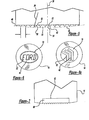
- Figure 1 is a schematic view of an ultrasonic welding apparatus according to a second aspect of the invention;
- Figure 2 is a side view of a sonotrode tip according to the a first aspect of the invention for use with an ultrasonic welding apparatus;
- Figure 2a is an enlarged view of the sonotrode tip according to the first aspect of the invention for use with an ultrasonic welding apparatus according to a second aspect of the invention;
- Figure 3 is a bottom view of the sonotrode tip shown in Figure 2;
- Figure 4 is a perspective view of the end of the sonotrode tip;
- Figure 5 is a side view of an alternative embodiment of a sonotrode tip used with an ultrasonic welding apparatus according to the second aspect of the invention;
- Figure 6 is a bottom view of a second alternative embodiment of a sonotrode tip used with an ultrasonic welding apparatus according to the second aspect of the invention;
- Figure 6a is a bottom view of a third alternative embodiment of a sonotrode tip used with an ultrasonic welding apparatus according to the second aspect of the invention;
- Figure 7 is a side view of a third alternative embodiment of a sonotrode tip used with an ultrasonic welding apparatus according to the second aspect of the invention; and
- Figure 8 is a side view of an apparatus for rotating an anvil for use with an ultrasonic welding apparatus according to the second aspect of the invention.
-
- FIG. 1 shows an ultrasonic welding apparatus, seen generally at 10, according to the present invention. The
ultrasonic welding apparatus 10 includes a reed 11 and asonotrode 12 mounted for movement in a side-to-side or horizontal direction of vibration, shown by thearrow 16. The reed 11 andsonotrode 12 also moves in a vertical manner, shown by thearrow 18, and in cooperation with ananvil 20 clamps the first 22 and second 24 workpieces in position. Once theworkpieces transducer 15 operates through awedge 17 to transfer high frequency vibrations from the transducer to the reed 11 to impart energy to the first 22 and second 24 workpieces at a location between thesonotrode 12 and theanvil 20 to create a bond or weld at the interface oradjacent surfaces 26 of theworkpieces term sonotrode 12 used herein refers generally to the reed 11 andsonotrode 12 combination as thesonotrode 12 is typically the gripping tool attached to the reed 11. - The
sonotrode 12 includes asonotrode tip 14. As shown in FIG. 2, thesonotrode tip 14 has a sphericalouter surface 28 on thedistal end 30 thereof. A plurality ofgrooves 32 are formed in the sphericalouter surface 28 and cooperate with a portion of the sphericalouter surface 28 to form acontact surface 31. The size or area of thecontact surface 31 may vary to pending upon the particular material to be welded. Thecontact surface 31 may be as large as the entire sphericalouter surface 28 or it may be limited to the area encompassing thegrooves 32. - The
grooves 32 extend inward from the sphericalouter surface 28 to acommon reference plane 46. Accordingly, thedeepest groove 32 is that one coincident with the high point or apex 36 of the sphericalouter surface 28. The high point or apex 36 is located on thelongitudinal axis 38 of thesonotrode 12. The sphericalouter surface 28 drops off or away the greater the distance from the center point or apex 36. - As the
grooves 32 each extend to acommon reference plane 46 they fade out on the sphericalouter surface 28 the farther they are from the high point or apex 36. In the preferred embodiment, the point at which thegrooves 32 fade out defines theperipheral edge 40 of thecontact surface 31. Since thegrooves 32 gradually fade out at theperipheral edge 40, the welding stresses at theperipheral edge 40 are less and, therefore, the weld is less likely to crack at the edges. - Turning to FIG. 2a, the
grooves 32 are shown arranged in a row pattern and the bottom orlower portion 35 of thegrooves 32 extends to areference plane 46. It is the position of thereference plane 46 that establishes the bottom of thegrooves 32 irrespective of their location on theouter surface 28. As shown, thegroove 32 includes sidewalls 33 extending at an angle 41 of approximately 60 degrees. Accordingly, thesidewalls 33 extend from the bottom orlower portion 35 of thegrooves 32, which are rounded to aland area 42. In the specific embodiment, for use in ultrasonically welding an aluminum workpiece, the depth of thereference plane 46 is 0.279mm (0.011 inches) when taken from the apex 36. The groove depth is a function of the thickness of the material to be welded. For instance, the ratio of the depth of thegroove 32 to the thickness of the material is roughly 0.01 to 0.04. - In addition, the depth of the
grooves 32 will vary along theouter surface 28 as the radius of theouter surface 28 varies. For instance, the invention contemplates the use of aspherical radius 29 of 12.7 to 102mm (0.5 inches to 4 inches). Accordingly, the area of the outerspherical surface 28 havinggrooves 32 is determined by the depth of thereference plane 46 at the apex 36 and the radius ofcurvature 29 of the sphericalouter surface 28. - FIG. 2a further shows an embodiment of the invention wherein the
grooves 32, at the apex 36, have a width (y) of 0.636mm (0.025 inches) and a space or area between thegrooves 32, defined as aland 42, having a width (x) of 0.279mm (0.011 inches). The width (x) of theland 42 is less than the width (y) of thegrooves 32. The respective widths may be expressed as a ratio, wherein the ratio of the width (x) of theland 42 to the width (y) of the groove is roughly 0.4 to 0.8. Having aland 42 width (x) less than the width (y) of thegroove 32 allows to theland 42 to press into theworkpiece 22. - As shown, the land/groove intersection defines a sharp and discrete edge or
corner 44 that aids in gripping theworkpiece 22. It should be understood the above dimensions are intended as an example only and depending upon the various parameters such as workpiece type their dimensions may change. Further, as the size or width of theland 42 increases, thesonotrode tip 14 sits on and slides back and forth on the surface of theworkpiece 22. Thus, in most instances, it is advisable to keep the width of theland 42 less than that of thegrooves 32. Although, in some instances, the respective widths can be varied along thecontact surface 31. - It should be understood all of the
grooves 32 are cut or ground to thereference plane 46, see FIGS. 2 and 2a. Specifically, therounded bottom 35 of eachgroove 32 lies in or adjacent thesame plane 46. Accordingly, while thecentermost groove 32 has the maximum depth with respect to theouter surface 28, correspondingadjacent grooves 32 decrease in depth as the sphericalouter surface 28 of thesonotrode tip 14 falls inward toward the plane defined by the bottom of thegrooves 32. - As shown in FIGS. 2 and 2a, the depth of the
groove 32 farthest from the apex 36 is less, when measured from the sphericalouter surface 28 than thegroove 32 located at the apex 36. Thus, the groove depth 34 fades out or decreases the closer to theperiphery 40 of thecontact surface 31 wherein thecontact surface 31 is that portion of the sphericalouter surface 28 that falls or extends underneath theplane 46 shown in FIG. 2. - Other configurations of
grooves 32 are also suitable for use with the present invention. As shown in FIG. 5, thegrooves 32 may be formed with asemi-circular cross-section 50. Eachgroove 32 is situated immediately adjacent thenext groove 32. Again, thegrooves 32 are all cut in thesame plane 46 wherein the bottom 52 of eachgroove 32 lies in thesame plane 46. Once again, due to the arcuate or convex curved surface of thesonotrode tip 14, thedepth 53 of thegroove 32 varies depending on the distance from the apex 36, with the depth decreasing the greater the distance from the apex 36 of the curved or sphericalouter surface 28. - Further, as the
grooves 32 are positioned adjacent one another, the thickness of thelands 42 at the very center of thesonotrode tip 14, i.e., near, the apex 36 is small. Correspondingly, the thickness of thelands 42 increases the further the location from the apex 36. - Additionally, as shown in FIGS. 6 and 6a, it is contemplated that a word or
term 70, a logo or specific design 72 or a part or vehicle identification number may be formed in thesonotrode tip 14 such that thesonotrode tip 14 imprints the logo or design as part of the weld on the workpiece surface. - In the case of the vehicle identification number, printing the number on various parts of the vehicle may aid in identification of the vehicle if the vehicle is ever lost or stolen. With such embodiments, the logo or design is engraved on the
sonotrode tip 14. Depending upon the specific logo design, it may be necessary to form the sonotrode tip with different curvatures other than one having a spherical surface as set forth above. Thelogo 70 is formed by a combination of thegrooves 32 and thelands 42. - It should be understood that the
sonotrode tip 14 is oriented in a direction such that the majority of thelands 42 andgrooves 32 or, ridges and relief portions of thelogo 70 are placed in a direction transverse the direction of vibration of thesonotrode 12. Once again, the corner or edge defined by the intersection of thelands 42 andgrooves 32 or the ridges and relief portion forming thelogo 70 should be relatively sharp or angular to ensure proper engagement between thesonotrode tip 14 andworkpiece 22 and correspondingly reduce sliding on theworkpiece 22 which, as set forth above, increases the likelihood of thesonotrode tip 14 sticking to theworkpiece 22. - In a further embodiment, the
sonotrode tip 14 may include a coating or be formed of a material that has physical properties that reduce its propensity to stick to the workpiece. For instance, thesonotrode tip 14, typically formed of M2 tool steel, may instead be formed of T1 tool steel, which has a high concentration of tungsten. - The increased tungsten content in the
sonotrode tip 14 results in a tip that is less likely to adhere to an aluminum workpiece. - Further, a tungsten coating may also be applied to the
sonotrode tip 14. The coating should have good adherence properties along with an ability to withstand the applied pressure and ultrasonic vibrations without cracking and peeling. Various types of surface treatments or coatings that could be used include, but are not limited to, physical vapor deposited (PVD) coatings of TiN, TiCN, Ti AIN, WC/C CrC, CRN or combinations thereof. In addition, chemical vapor deposited (CVD) coatings of similar types may be used. In addition, electroplated or electroless coatings like chromium or nickel can be used. Finally a surface modification or diffusion process like a plasma nitriding process, a tungsten implanting process or plasma immersion ion process can be used to implant various materials such as tungsten or chromium. - The
sonotrode tip 14 may also utilize aninsert 60, such as shown in FIG. 7. In such an embodiment, anotch 62 is cut in thesonotrode tip 14 and aninsert 60, typically formed of a tungsten material as set forth above, is secured within thenotch 62. The insert may also a formed of a hydrate material, i.e., one that has water contained therein such as bohemite, or aluminum oxide, Al2O3·nH2O that, when heated, loses or emits the water or moisture contained therein. - Accordingly, since the temperature of the
sonotrode tip 14 rises during the ultrasonic welding process, some of the water or moisture contained in the insert is released. Absorption from the atmosphere replenishes the consumed or applied water between welds. Such a hydrated material may also be applied as a surface layer, e.g., a hydrated oxide. It should be understood that applying water or some other liquid between thesonotrode tip 14 and theworkpiece 22 decreases the likelihood that thesonotrode tip 14 will stick to theworkpiece 22. - While the
insert 60 shown in the preferred embodiment includes grooves, theinsert 60 may also utilize a standard knurled pattern or any other pattern found to suitably grip the workpiece during the ultrasonic welding procedure. - Finally, an alternative embodiment includes a rotatable anvil feature that, in the preferred embodiment, operates in connection with a
non-stick sonotrode tip 14. As shown in FIG. 8, theanvil 20 is rotatably supported in a base orsupport member 78. - A
motor 80 drives ashaft member 82 having oneend 84 thereof connected theanvil 20. As shown, a control member and 86 sends a signal through acontrol line 87 to energize themotor 80 and rotate theanvil 20 in thedirection 88 about anaxis 90 perpendicular to the plane of thelower workpiece 24. It should be understood that other mechanisms capable of rotating theanvil 20 might also be used. The main thrust being the use of a rotational motion to dislodge theanvil 20 from theworkpiece 24 rather than an axial or pulling motion. - As set forth above, the
anvil 20 may include a groove or pattern configuration similar to that of thesonotrode tip 14 set forth above or it may utilize a traditional knurl pattern. If theanvil 20 utilizes agroove 32 andland 42 pattern such as that used on thesonotrode tip 14 then it is advisable to linearly offset therespective groove 32 andland 42 pattern of thesonotrode tip 14 andanvil 20 by 15 to 20 degrees. - For instance, while the grooves of the
respective sonotrode tip 14 andanvil 20 remain perpendicular to the direction of vibration and parallel to one another, they are offset such that the corresponding grooves and lands are not immediately opposite one another. - Using the
sonotrode tip 14 reduces the likelihood that theworkpiece 22 will stick to thesonotrode tip 14. - Accordingly, by manipulating the surfaces of the
respective sonotrode tip 14 andanvil 20, it is possible to control any sticking. - Accordingly, if the
anvil 20 sticks to the workpiece, rotation of theanvil 20 in the plane of theworkpiece 24 will free the workpiece 24 from the anvil. If used, the knurled or diamond shape surface of theanvil 20 acts as a cam surface that, when rotated, operates to drive or lift the workpiece 24 from the knurled surface. - The
anvil 20 may also be coated with a material to reduce sticking as for thesonotrode tip 14. - Therefore in summary, the present invention provides an ultrasonic welding apparatus configured such that it reduces adhesion between the welding apparatus and the workpiece during the ultrasonic welding process and a sonotrode tip for use in such an apparatus. In one embodiment thereof, the apparatus includes an arcuate shaped sonotrode tip having a plurality of grooves formed therein. The grooves extend perpendicular to the direction of sonotrode vibration. The length and depth of each groove depends in part upon the curvature of the sonotrode tip surface. The sonotrode tip also includes a plurality of lands formed adjacent to the grooves.
- A surface treatment is provided on the sonotrode tip to reduce adhesion of the tip to the workpiece. The surface treatment may include an insert formed of a stick-resistant material placed on the sonotrode tip.
- Rotation of the anvil of the ultrasonic welding apparatus after the weld is completed may used to release the workpiece from the ultrasonic welding apparatus.
- Rotation of the anvil may be combined with the use of a sonotrode tip having reduced adhesion properties such that any sticking occurs at the anvil/workpiece interface rather than the sonotrode/workpiece interface.
- Accordingly, the ultrasonic welding apparatus operates to reduce or control sticking of the sonotrode to the material or workpiece while having suitable gripping ability to transfer energy from the sonotrode to the workpiece to perform the ultrasonic welding process.
- It will be appreciated that modifications and variations of the embodiments disclosed without departing from the scope of the present invention as defined by the appended claims.
Claims (10)
- A sonotrode tip (14) for attachment to a sonotrode (12) of an ultrasonic welding apparatus (10)for bonding workpieces together using the sonotrode (12) and an anvil (20) characterised in that the tip (14) has a plurality of grooves (32) formed in a curvilinear shaped outer surface thereof, the outer surface (28) cooperating with the grooves to define a contact surface (31) for abutment against a workpiece.
- A sonotrode tip as claimed in claim 1 wherein the depth of the grooves (32) formed in the outer surface gradually decreases as they near the periphery of the contact surface (31).
- A sonotrode tip as claimed in claim 1 or in claim 2 wherein at least one of the length and the width of the grooves (32) varies depending upon the location of the grooves on the outer surface (28).
- A sonotrode tip as claimed in any of claims 1 to 3 wherein the grooves (32) have a semicircular shaped cross-section (50).
- A sonotrode tip as claimed in any of claims 1 to 4 wherein lands (42) are positioned adjacent the grooves (32), the lands (42) being narrower than the grooves (32).
- A sonotrode tip as claimed in any of claims 1 to 5 wherein the tip (14) includes a coating on the outer surface (28) thereof that reduces the propensity of the tip (14) to stick to the workpiece (22).
- A sonotrode tip as claimed in any of claims 1 to 6 wherein the tip (14) includes an insert (60) formed of one of a tungsten material that reduces sticking of the tip (14) to the workpieces (22, 24) and a hydrate material that releases moisture.
- An ultrasonic welding apparatus for bonding workpieces (22, 24) together using a sonotrode (12) and an anvil (20)characterised in that the apparatus includes a sonotrode tip (14) as claimed in any of claims 1 to 7 attached to the sonotrode (12).
- An apparatus as claimed in claim 8 wherein the anvil (20) includes a pattern of grooves similar to that of the tip wherein the pattern on the anvil (20)is offset from the pattern of the tip (14) by an angle of between 15 and 20 degrees.
- An apparatus as claimed in claim 8 or in claim 9 wherein the anvil (20) is rotatably mounted on a support member (78) and is driveably connected to a motor (80), the motor (80) being selectively operable to rotate the anvil (20) about an axis (90) perpendicular to a contact surface of the anvil (20).
Applications Claiming Priority (2)
| Application Number | Priority Date | Filing Date | Title |
|---|---|---|---|
| US09/682,729 US6523732B1 (en) | 2001-10-10 | 2001-10-10 | Ultrasonic welding apparatus |
| US682729 | 2001-10-10 |
Publications (2)
| Publication Number | Publication Date |
|---|---|
| EP1302272A1 true EP1302272A1 (en) | 2003-04-16 |
| EP1302272B1 EP1302272B1 (en) | 2005-04-06 |
Family
ID=24740891
Family Applications (1)
| Application Number | Title | Priority Date | Filing Date |
|---|---|---|---|
| EP02102336A Expired - Lifetime EP1302272B1 (en) | 2001-10-10 | 2002-09-09 | An ultrasonic welding tip and apparatus with this tip |
Country Status (4)
| Country | Link |
|---|---|
| US (1) | US6523732B1 (en) |
| EP (1) | EP1302272B1 (en) |
| JP (1) | JP2003117663A (en) |
| DE (1) | DE60203579T2 (en) |
Cited By (1)
| Publication number | Priority date | Publication date | Assignee | Title |
|---|---|---|---|---|
| US5440280A (en) * | 1993-09-17 | 1995-08-08 | Mpr Teltech Ltd. | Digital microwave multi-bit attenuator |
Families Citing this family (62)
| Publication number | Priority date | Publication date | Assignee | Title |
|---|---|---|---|---|
| US6732901B2 (en) * | 2001-06-12 | 2004-05-11 | Brigham Young University Technology Transfer Office | Anvil for friction stir welding high temperature materials |
| JP3742332B2 (en) * | 2001-11-12 | 2006-02-01 | 株式会社新川 | Wire bonding equipment |
| US20040024843A1 (en) * | 2002-07-31 | 2004-02-05 | Smith Christopher T. | Method for provisioning distributed web applications |
| DE10330431B3 (en) * | 2003-07-04 | 2005-01-05 | Schunk Ultraschalltechnik Gmbh | welder |
| JP4274885B2 (en) * | 2003-09-19 | 2009-06-10 | 三菱電機株式会社 | Ultrasonic bonding apparatus and ultrasonic bonding method |
| WO2005044542A1 (en) * | 2003-11-05 | 2005-05-19 | Daniel Suhm | Method and device for print embossing surfaces |
| JP2005159061A (en) * | 2003-11-27 | 2005-06-16 | Fujitsu Ltd | Ultrasonic tool and ultrasonic bonding apparatus |
| US20060163315A1 (en) | 2005-01-27 | 2006-07-27 | Delsman Mark A | Ribbon bonding tool and process |
| CN100522449C (en) * | 2005-01-28 | 2009-08-05 | 日产自动车株式会社 | Ultrasonic bonding equipment and resulting bonding structure |
| JP4792945B2 (en) * | 2005-01-28 | 2011-10-12 | 日産自動車株式会社 | Ultrasonic bonding apparatus and bonded structure |
| DE102005004899A1 (en) * | 2005-02-02 | 2006-08-03 | Schunk Ultraschalltechnik Gmbh | Compression space of an ultrasonic welding device for welding metal conductors together has structured lateral surfaces |
| US7698797B2 (en) * | 2005-02-02 | 2010-04-20 | Ford Global Technologies | Apparatus and method for forming a joint between adjacent members |
| US7229523B2 (en) * | 2005-03-31 | 2007-06-12 | Xerox Corporation | Treatment for ultrasonic welding |
| JP4609169B2 (en) * | 2005-04-15 | 2011-01-12 | 日産自動車株式会社 | Ultrasonic bonding method |
| US7748590B2 (en) * | 2005-05-16 | 2010-07-06 | Ford Global Technologies, Llc | Ultrasonic welding apparatus |
| US8196797B2 (en) * | 2006-05-23 | 2012-06-12 | Federal-Mogul Corporation | Powder metal ultrasonic welding tool and method of manufacture thereof |
| US20080023529A1 (en) * | 2006-07-25 | 2008-01-31 | Larry Van Reatherford | Ultrasonic welding apparatus |
| JP4977441B2 (en) * | 2006-10-31 | 2012-07-18 | 矢崎総業株式会社 | Ultrasonic bonding equipment |
| US7666541B2 (en) * | 2006-11-03 | 2010-02-23 | The Gillette Company | Ultrasonic metal welding techniques and batteries manufactured using such techniques |
| KR20100014316A (en) * | 2007-04-27 | 2010-02-10 | 파나소닉 주식회사 | Electronic part mounting apparatus and method of mounting electronic part |
| DE102008014320A1 (en) * | 2008-03-14 | 2009-09-17 | Fraunhofer-Gesellschaft zur Förderung der angewandten Forschung e.V. | Ultrasonic assisted friction stir welding |
| WO2010091222A2 (en) * | 2009-02-06 | 2010-08-12 | Orthodyne Electronics Corporation | Ribbon bonding tools and methods of using the same |
| US10847491B2 (en) | 2009-02-06 | 2020-11-24 | Kulicke And Soffa Industries, Inc. | Ribbon bonding tools and methods of using the same |
| US20120125520A1 (en) * | 2009-06-23 | 2012-05-24 | Toshiba Mitsubishi-Electric Industrial. Sys. Corp. | Ultrasonic bonding tool, method for manufacturing ultrasonic bonding tool, ultrasonic bonding method, and ultrasonic bonding apparatus |
| US8129220B2 (en) * | 2009-08-24 | 2012-03-06 | Hong Kong Polytechnic University | Method and system for bonding electrical devices using an electrically conductive adhesive |
| US8011559B2 (en) * | 2009-11-09 | 2011-09-06 | GM Global Technology Operations LLC | Active material-augmented vibration welding system and method of use |
| US8730656B2 (en) | 2010-11-12 | 2014-05-20 | Apple Inc. | Unitary housing for electronic device |
| US9040120B2 (en) | 2011-08-05 | 2015-05-26 | Frito-Lay North America, Inc. | Inorganic nanocoating primed organic film |
| KR101251114B1 (en) * | 2011-08-17 | 2013-04-04 | 오종필 | A sewing machine using ultrasonic wave |
| WO2013112205A2 (en) * | 2011-09-20 | 2013-08-01 | Orthodyne Electronics Corporation | Wire bonding tool |
| DE102011084503A1 (en) * | 2011-10-14 | 2013-04-18 | Robert Bosch Gmbh | Welding element for welding a contact element with a connection element |
| US9162421B2 (en) | 2012-04-25 | 2015-10-20 | Frito-Lay North America, Inc. | Film with compostable heat seal layer |
| JP2013226580A (en) * | 2012-04-26 | 2013-11-07 | Mitsubishi Electric Corp | Ultrasonic vibration joining apparatus |
| US9284104B2 (en) | 2012-06-23 | 2016-03-15 | Frito-Lay North America, Inc. | Deposition of ultra-thin inorganic oxide coatings on packaging |
| US9149980B2 (en) | 2012-08-02 | 2015-10-06 | Frito-Lay North America, Inc. | Ultrasonic sealing of packages |
| US9090021B2 (en) * | 2012-08-02 | 2015-07-28 | Frito-Lay North America, Inc. | Ultrasonic sealing of packages |
| DE102012112413A1 (en) * | 2012-12-17 | 2014-06-18 | Hesse Gmbh | Tool for producing a friction-welded connection |
| KR20140110353A (en) * | 2013-03-07 | 2014-09-17 | 삼성에스디아이 주식회사 | Ultrasound horn and secondary battery manufactured using the same |
| CN103219255A (en) * | 2013-03-15 | 2013-07-24 | 李尚哲 | An ultrasonic welding chopper with multiple welding wire slots |
| EP2873517B1 (en) * | 2013-11-14 | 2019-04-24 | Airbus Defence and Space GmbH | Stabilising device, stabilising process and method for producing fibre compound components |
| JP6493782B2 (en) * | 2014-12-04 | 2019-04-03 | 株式会社Gsユアサ | Ultrasonic bonding apparatus and method for manufacturing power storage element using ultrasonic bonding apparatus |
| US9981336B2 (en) * | 2015-11-04 | 2018-05-29 | Kulicke And Soffa Industries, Inc. | Ribbon bonding tools, and methods of designing ribbon bonding tools |
| JP6646872B2 (en) * | 2016-03-09 | 2020-02-14 | 株式会社オートネットワーク技術研究所 | Manufacturing method of electric wire with terminal and electric wire with terminal |
| CN109526212B (en) * | 2016-08-04 | 2021-03-23 | 东芝三菱电机产业系统株式会社 | Ultrasonic bonding tool and ultrasonic bonding device |
| US10570501B2 (en) | 2017-05-31 | 2020-02-25 | Kennametal Inc. | Multilayer nitride hard coatings |
| JP2019005776A (en) * | 2017-06-22 | 2019-01-17 | イーグル工業株式会社 | Ultrasonic joining method, ultrasonic joining jig, and joint structure |
| JP2019013959A (en) * | 2017-07-06 | 2019-01-31 | イーグル工業株式会社 | Ultrasonic joining jig, joining structure and joining method |
| DE102017126533B3 (en) * | 2017-11-13 | 2018-11-29 | Auto-Kabel Management Gmbh | Method and device for embossing components |
| CN108389806B (en) * | 2018-01-22 | 2019-04-23 | 潮州三环(集团)股份有限公司 | A rivet for improving wire bond strength |
| US11697172B2 (en) * | 2019-09-05 | 2023-07-11 | Ohio State Innovation Foundation | Systems and methods for joining and repair using ultrasonic additive manufacturing with a contoured sonotrode |
| US10981245B2 (en) * | 2019-09-24 | 2021-04-20 | GM Global Technology Operations LLC | Apparatus for ultrasonic welding of polymers and polymeric composites |
| US11141925B2 (en) | 2019-10-31 | 2021-10-12 | GM Global Technology Operations LLC | Ultrasonic welding and welding horn having indenter |
| CN112222596A (en) * | 2020-10-20 | 2021-01-15 | 天津市捷威动力工业有限公司 | Ultrasonic welding method for soft package lithium battery tab |
| US11772187B2 (en) * | 2021-04-30 | 2023-10-03 | Infineon Technologies Ag | Ultrasonic welding device |
| CN114178670A (en) * | 2021-11-27 | 2022-03-15 | 万向一二三股份公司 | Ultrasonic welding horn structure |
| US12617037B2 (en) * | 2021-12-16 | 2026-05-05 | Schunk Sonosystems Gmbh | Ultrasonic welding device comprising a sonotrode carrier and a sonotrode fastened thereto |
| JP7595559B2 (en) * | 2021-12-21 | 2024-12-06 | 三菱電機株式会社 | Semiconductor manufacturing apparatus and method for manufacturing semiconductor device |
| EP4261017A1 (en) * | 2022-04-13 | 2023-10-18 | Telsonic Holding AG | Tool, method for welding and welded workpiece |
| CN218694876U (en) * | 2022-11-30 | 2023-03-24 | 宁德时代新能源科技股份有限公司 | Processing mechanism and ultrasonic welding device |
| DE102023102293A1 (en) * | 2023-01-31 | 2024-08-01 | Herrmann Ultraschalltechnik Gmbh & Co. Kg | Reduced voltage sonotrode |
| DE102023119422A1 (en) * | 2023-07-21 | 2025-01-23 | Herrmann Ultraschalltechnik Gmbh & Co. Kg | machining element with engraving section |
| WO2025080465A1 (en) * | 2023-10-12 | 2025-04-17 | Kulicke And Soffa Industries, Inc. | Wedge bonding tools and methods of forming wire bonds |
Citations (8)
| Publication number | Priority date | Publication date | Assignee | Title |
|---|---|---|---|---|
| GB884306A (en) * | 1958-08-13 | 1961-12-13 | Darchem Engineering Ltd | Improvements in or relating to the welding of metals |
| GB1248892A (en) * | 1969-01-22 | 1971-10-06 | Siemens Ag | Improvements in or relating to ultrasonic welding heads and their manufacture |
| US3750926A (en) * | 1971-03-02 | 1973-08-07 | Hitachi Ltd | Vibration element for supersonic bonding |
| DE2726137A1 (en) * | 1977-06-10 | 1978-12-21 | Otto Siebeck Gmbh | Vibrator for supersonic welding of plastics components - has sonotrode with fluted or ribbed welding surface |
| JPS60201928A (en) * | 1984-03-27 | 1985-10-12 | Yoshino Kogyosho Co Ltd | Horn for ultrasonic sealing |
| JPH01249281A (en) * | 1988-03-28 | 1989-10-04 | American Technol Inc | Ultrasonic welder and ultrasonic welding nose section used for said device and ultrasonic welding method |
| GB2285943A (en) * | 1994-01-28 | 1995-08-02 | Hewlett Packard Co | Bonding tool for electronic device |
| DE19749682A1 (en) * | 1997-11-10 | 1999-05-12 | Draexlmaier Lisa Gmbh | Nondestructive testing of a welded connector |
Family Cites Families (31)
| Publication number | Priority date | Publication date | Assignee | Title |
|---|---|---|---|---|
| US3438428A (en) | 1965-03-04 | 1969-04-15 | Cavitron Corp | Method for maintaining a vibratory tool at a controlled temperature |
| US3291957A (en) | 1965-10-12 | 1966-12-13 | Albert G Bodine | Method and apparatus for removal of insulation coating of parts in spot welding |
| US3529660A (en) | 1968-11-20 | 1970-09-22 | Branson Instr | Solid horn with cooling means |
| US3765589A (en) * | 1970-06-01 | 1973-10-16 | T Walraven | Welding apparatus |
| DE2312724C2 (en) * | 1973-03-14 | 1974-06-06 | Siemens Ag, 1000 Berlin Und 8000 Muenchen | Method and device for ultrasonic welding of a component made of metal with a component made of a non-metal with the insertion of a metallic intermediate layer |
| US4194937A (en) | 1978-10-16 | 1980-03-25 | L. M. Rabinowitz & Co., Inc. | Apparatus for processing hook and eye fasteners |
| CH654247A5 (en) * | 1981-11-02 | 1986-02-14 | Sig Schweiz Industrieges | ULTRASONIC WELDING DEVICE AND USE THEREOF. |
| US4527727A (en) | 1983-04-12 | 1985-07-09 | Fairchild Industries, Inc. | Stabilized ultrasonic welding apparatus |
| US4545519A (en) | 1983-04-12 | 1985-10-08 | Fairchild Industries, Inc. | Method and apparatus for preventing tip sticking during welding operation |
| US4529115A (en) | 1983-04-12 | 1985-07-16 | Fairchild Industries, Inc. | Thermally assisted ultrasonic welding apparatus and process |
| US4647325A (en) | 1984-07-12 | 1987-03-03 | Presto Products, Incorporated | Ultrasonic spot welding tip assembly and method for using the same |
| US4572753A (en) | 1984-07-12 | 1986-02-25 | The Coca-Cola Company | Method of ultrasonic welding and apparatus therefor |
| JPH0613193B2 (en) | 1987-03-16 | 1994-02-23 | 富士写真フイルム株式会社 | Method for laminating thermoplastic resin member |
| US5147082A (en) | 1987-08-17 | 1992-09-15 | Siemens Aktiengesellschaft | Tool configuration for ultrasonic welding |
| DE8902562U1 (en) * | 1989-03-03 | 1990-07-05 | Robert Bosch Gmbh, 7000 Stuttgart | Ultrasonic welding device |
| DE4128858C1 (en) * | 1991-08-30 | 1993-01-21 | Stapla Ultraschall-Technik Gmbh, 6092 Kelsterbach, De | |
| CH687739A5 (en) | 1992-12-12 | 1997-02-14 | Thera Ges Fuer Patente | Method and apparatus for the production of horns for the ultrasonic machining as ceramic workpieces, particularly for oral surgery. |
| US5540808A (en) | 1993-02-24 | 1996-07-30 | Deka Products Limited Partnership | Energy director for ultrasonic welding and joint produced thereby |
| US5800672A (en) | 1994-06-07 | 1998-09-01 | Aztex, Inc. | Ultrasonic fastening system and method |
| US5575884A (en) | 1994-09-28 | 1996-11-19 | Tetra Laval Holdings & Finance S.A. | Ultrasonic piston converter |
| JP3456293B2 (en) | 1995-03-17 | 2003-10-14 | 株式会社デンソー | Ultrasonic welding method for dissimilar metals |
| JPH0952185A (en) | 1995-08-14 | 1997-02-25 | Yazaki Corp | Ultrasonic welding machine |
| JPH09206963A (en) | 1996-01-29 | 1997-08-12 | Yazaki Corp | Ultrasonic bonding method |
| EP0787557A3 (en) | 1996-01-30 | 1998-07-22 | Suzuki Motor Corporation | Method of bonding aluminum members |
| US5772100A (en) | 1996-03-22 | 1998-06-30 | American Technology, Inc. | Ultrasonic welder with dynamic nodal horn support |
| JP3295328B2 (en) | 1997-01-09 | 2002-06-24 | 矢崎総業株式会社 | Ultrasonic connection terminal |
| JP3229238B2 (en) | 1997-03-03 | 2001-11-19 | 本田技研工業株式会社 | Ultrasonic bonding method for metal foil |
| WO2000000344A1 (en) * | 1998-06-30 | 2000-01-06 | Trustees Of Tufts College | Multiple-material prototyping by ultrasonic adhesion |
| US6176953B1 (en) | 1998-09-22 | 2001-01-23 | Motorola, Inc. | Ultrasonic welding process |
| JP2000141489A (en) | 1998-11-12 | 2000-05-23 | Pop Rivet Fastener Kk | Ultrasonic welding apparatus and method |
| EP1010492B1 (en) | 1998-12-10 | 2004-09-01 | Ultex Corporation | Ultrasonic vibration bonding method |
-
2001
- 2001-10-10 US US09/682,729 patent/US6523732B1/en not_active Expired - Lifetime
-
2002
- 2002-09-09 DE DE60203579T patent/DE60203579T2/en not_active Expired - Lifetime
- 2002-09-09 EP EP02102336A patent/EP1302272B1/en not_active Expired - Lifetime
- 2002-10-09 JP JP2002296405A patent/JP2003117663A/en active Pending
Patent Citations (8)
| Publication number | Priority date | Publication date | Assignee | Title |
|---|---|---|---|---|
| GB884306A (en) * | 1958-08-13 | 1961-12-13 | Darchem Engineering Ltd | Improvements in or relating to the welding of metals |
| GB1248892A (en) * | 1969-01-22 | 1971-10-06 | Siemens Ag | Improvements in or relating to ultrasonic welding heads and their manufacture |
| US3750926A (en) * | 1971-03-02 | 1973-08-07 | Hitachi Ltd | Vibration element for supersonic bonding |
| DE2726137A1 (en) * | 1977-06-10 | 1978-12-21 | Otto Siebeck Gmbh | Vibrator for supersonic welding of plastics components - has sonotrode with fluted or ribbed welding surface |
| JPS60201928A (en) * | 1984-03-27 | 1985-10-12 | Yoshino Kogyosho Co Ltd | Horn for ultrasonic sealing |
| JPH01249281A (en) * | 1988-03-28 | 1989-10-04 | American Technol Inc | Ultrasonic welder and ultrasonic welding nose section used for said device and ultrasonic welding method |
| GB2285943A (en) * | 1994-01-28 | 1995-08-02 | Hewlett Packard Co | Bonding tool for electronic device |
| DE19749682A1 (en) * | 1997-11-10 | 1999-05-12 | Draexlmaier Lisa Gmbh | Nondestructive testing of a welded connector |
Non-Patent Citations (2)
| Title |
|---|
| PATENT ABSTRACTS OF JAPAN vol. 010, no. 051 (M - 457) 28 February 1986 (1986-02-28) * |
| PATENT ABSTRACTS OF JAPAN vol. 2000, no. 17 5 June 2001 (2001-06-05) * |
Cited By (1)
| Publication number | Priority date | Publication date | Assignee | Title |
|---|---|---|---|---|
| US5440280A (en) * | 1993-09-17 | 1995-08-08 | Mpr Teltech Ltd. | Digital microwave multi-bit attenuator |
Also Published As
| Publication number | Publication date |
|---|---|
| EP1302272B1 (en) | 2005-04-06 |
| DE60203579D1 (en) | 2005-05-12 |
| DE60203579T2 (en) | 2006-05-04 |
| JP2003117663A (en) | 2003-04-23 |
| US6523732B1 (en) | 2003-02-25 |
Similar Documents
| Publication | Publication Date | Title |
|---|---|---|
| EP1302272B1 (en) | An ultrasonic welding tip and apparatus with this tip | |
| JP4164116B2 (en) | Insert tip | |
| JP6297047B2 (en) | Coated cutting tool with patterned surface area | |
| US7905690B2 (en) | Spade bit | |
| JP2007152477A (en) | Manufacturing method of surface coated cutting insert | |
| JP6618896B2 (en) | Screw with screw head, drive tool and drive system | |
| JP2004237410A (en) | Cutting device | |
| EP0739697B2 (en) | Rotary cutting tool for working of wood or wood composite material | |
| JP4897829B2 (en) | Manufacturing method of arc-type nail-cutting blade body, nail-cutting blade body by this, and nail-cutting device | |
| KR102089858B1 (en) | End mill | |
| JP6602804B2 (en) | Cutting tools | |
| JP3637815B2 (en) | Metal tin coating equipment and seam welding machine for copper wire for seam welding | |
| JP3680737B2 (en) | Seam welding method for thin chrome plated steel sheet | |
| JP3191238B2 (en) | Finger cutter | |
| JP2013111179A (en) | Single-edged cutting tool and method for finishing edge body | |
| JP2011206897A (en) | Drill, and insert for drill | |
| US5839402A (en) | Wear resistant tappet | |
| CN101605629A (en) | Surface treatment method of coated cutting inserts | |
| CN116690366B (en) | Dental needle and manufacturing method thereof | |
| CN217070775U (en) | Coating for machining stainless steel turning tool | |
| US20080250722A1 (en) | Electroplated abrasive tools, methods, and molds | |
| US20070137020A1 (en) | Method and apparatus for forming a metallic container | |
| JPS6312927Y2 (en) | ||
| JPH09239562A (en) | Cutter for electrode tip dresser | |
| JPS6312926Y2 (en) |
Legal Events
| Date | Code | Title | Description |
|---|---|---|---|
| PUAI | Public reference made under article 153(3) epc to a published international application that has entered the european phase |
Free format text: ORIGINAL CODE: 0009012 |
|
| AK | Designated contracting states |
Designated state(s): AT BE BG CH CY CZ DE DK EE ES FI FR GB GR IE IT LI LU MC NL PT SE SK TR |
|
| AX | Request for extension of the european patent |
Extension state: AL LT LV MK RO SI |
|
| 17P | Request for examination filed |
Effective date: 20030911 |
|
| AKX | Designation fees paid |
Designated state(s): DE GB SE |
|
| 17Q | First examination report despatched |
Effective date: 20040116 |
|
| GRAP | Despatch of communication of intention to grant a patent |
Free format text: ORIGINAL CODE: EPIDOSNIGR1 |
|
| GRAS | Grant fee paid |
Free format text: ORIGINAL CODE: EPIDOSNIGR3 |
|
| GRAA | (expected) grant |
Free format text: ORIGINAL CODE: 0009210 |
|
| RAP1 | Party data changed (applicant data changed or rights of an application transferred) |
Owner name: FORD GLOBAL TECHNOLOGIES, LLC |
|
| AK | Designated contracting states |
Kind code of ref document: B1 Designated state(s): DE GB SE |
|
| REG | Reference to a national code |
Ref country code: GB Ref legal event code: FG4D |
|
| REG | Reference to a national code |
Ref country code: IE Ref legal event code: FG4D |
|
| REF | Corresponds to: |
Ref document number: 60203579 Country of ref document: DE Date of ref document: 20050512 Kind code of ref document: P |
|
| REG | Reference to a national code |
Ref country code: SE Ref legal event code: TRGR |
|
| PLBE | No opposition filed within time limit |
Free format text: ORIGINAL CODE: 0009261 |
|
| STAA | Information on the status of an ep patent application or granted ep patent |
Free format text: STATUS: NO OPPOSITION FILED WITHIN TIME LIMIT |
|
| 26N | No opposition filed |
Effective date: 20060110 |
|
| REG | Reference to a national code |
Ref country code: GB Ref legal event code: 746 Effective date: 20061102 |
|
| REG | Reference to a national code |
Ref country code: GB Ref legal event code: 732E |
|
| PGFP | Annual fee paid to national office [announced via postgrant information from national office to epo] |
Ref country code: AT Payment date: 20180810 Year of fee payment: 17 |
|
| PGFP | Annual fee paid to national office [announced via postgrant information from national office to epo] |
Ref country code: GB Payment date: 20190827 Year of fee payment: 18 |
|
| PG25 | Lapsed in a contracting state [announced via postgrant information from national office to epo] |
Ref country code: SE Free format text: LAPSE BECAUSE OF NON-PAYMENT OF DUE FEES Effective date: 20190910 |
|
| REG | Reference to a national code |
Ref country code: SE Ref legal event code: EUG |
|
| PGFP | Annual fee paid to national office [announced via postgrant information from national office to epo] |
Ref country code: DE Payment date: 20200819 Year of fee payment: 19 |
|
| GBPC | Gb: european patent ceased through non-payment of renewal fee |
Effective date: 20200909 |
|
| PG25 | Lapsed in a contracting state [announced via postgrant information from national office to epo] |
Ref country code: GB Free format text: LAPSE BECAUSE OF NON-PAYMENT OF DUE FEES Effective date: 20200909 |
|
| REG | Reference to a national code |
Ref country code: DE Ref legal event code: R119 Ref document number: 60203579 Country of ref document: DE |
|
| PG25 | Lapsed in a contracting state [announced via postgrant information from national office to epo] |
Ref country code: DE Free format text: LAPSE BECAUSE OF NON-PAYMENT OF DUE FEES Effective date: 20220401 |