EP1301784B1 - Vorrichtung zur messung der konzentration eines analyts in einer flüssigkeit - Google Patents
Vorrichtung zur messung der konzentration eines analyts in einer flüssigkeit Download PDFInfo
- Publication number
- EP1301784B1 EP1301784B1 EP01949722A EP01949722A EP1301784B1 EP 1301784 B1 EP1301784 B1 EP 1301784B1 EP 01949722 A EP01949722 A EP 01949722A EP 01949722 A EP01949722 A EP 01949722A EP 1301784 B1 EP1301784 B1 EP 1301784B1
- Authority
- EP
- European Patent Office
- Prior art keywords
- test
- pusher
- magazine
- working area
- seal
- Prior art date
- Legal status (The legal status is an assumption and is not a legal conclusion. Google has not performed a legal analysis and makes no representation as to the accuracy of the status listed.)
- Expired - Lifetime
Links
- 239000012530 fluid Substances 0.000 title claims abstract description 13
- 239000012491 analyte Substances 0.000 title claims abstract description 8
- 238000012360 testing method Methods 0.000 claims abstract description 128
- 239000008280 blood Substances 0.000 claims description 11
- 210000004369 blood Anatomy 0.000 claims description 11
- 239000003153 chemical reaction reagent Substances 0.000 claims description 8
- WQZGKKKJIJFFOK-GASJEMHNSA-N Glucose Natural products OC[C@H]1OC(O)[C@H](O)[C@@H](O)[C@@H]1O WQZGKKKJIJFFOK-GASJEMHNSA-N 0.000 claims description 6
- 238000005520 cutting process Methods 0.000 claims description 6
- 239000008103 glucose Substances 0.000 claims description 6
- 230000001419 dependent effect Effects 0.000 claims description 2
- 125000002791 glucosyl group Chemical group C1([C@H](O)[C@@H](O)[C@H](O)[C@H](O1)CO)* 0.000 claims 1
- 230000000977 initiatory effect Effects 0.000 claims 1
- 230000007246 mechanism Effects 0.000 description 10
- 239000000976 ink Substances 0.000 description 9
- 239000011888 foil Substances 0.000 description 6
- 230000009471 action Effects 0.000 description 4
- 238000005299 abrasion Methods 0.000 description 2
- 230000008901 benefit Effects 0.000 description 2
- 238000004049 embossing Methods 0.000 description 2
- 238000005259 measurement Methods 0.000 description 2
- 238000000034 method Methods 0.000 description 2
- -1 poly(butylene terephthalate) Polymers 0.000 description 2
- 229920001707 polybutylene terephthalate Polymers 0.000 description 2
- 230000008569 process Effects 0.000 description 2
- 238000007650 screen-printing Methods 0.000 description 2
- 238000003892 spreading Methods 0.000 description 2
- 230000007480 spreading Effects 0.000 description 2
- SYJPAKDNFZLSMV-HYXAFXHYSA-N (Z)-2-methylpropanal oxime Chemical compound CC(C)\C=N/O SYJPAKDNFZLSMV-HYXAFXHYSA-N 0.000 description 1
- PXAGFNRKXSYIHU-UHFFFAOYSA-N 1,3-dichloro-2-(2,6-dichlorophenyl)benzene Chemical compound ClC1=CC=CC(Cl)=C1C1=C(Cl)C=CC=C1Cl PXAGFNRKXSYIHU-UHFFFAOYSA-N 0.000 description 1
- OKTJSMMVPCPJKN-UHFFFAOYSA-N Carbon Chemical compound [C] OKTJSMMVPCPJKN-UHFFFAOYSA-N 0.000 description 1
- 230000002457 bidirectional effect Effects 0.000 description 1
- 210000001124 body fluid Anatomy 0.000 description 1
- 229910052799 carbon Inorganic materials 0.000 description 1
- 238000010276 construction Methods 0.000 description 1
- 230000001351 cycling effect Effects 0.000 description 1
- 230000000881 depressing effect Effects 0.000 description 1
- 230000000994 depressogenic effect Effects 0.000 description 1
- 206010012601 diabetes mellitus Diseases 0.000 description 1
- 229940079593 drug Drugs 0.000 description 1
- 239000003814 drug Substances 0.000 description 1
- 238000001035 drying Methods 0.000 description 1
- 238000000840 electrochemical analysis Methods 0.000 description 1
- 238000004519 manufacturing process Methods 0.000 description 1
- 239000000463 material Substances 0.000 description 1
- 229920003023 plastic Polymers 0.000 description 1
- 239000004033 plastic Substances 0.000 description 1
- 230000002028 premature Effects 0.000 description 1
- 238000003825 pressing Methods 0.000 description 1
- 230000000750 progressive effect Effects 0.000 description 1
- 230000001681 protective effect Effects 0.000 description 1
- 239000007787 solid Substances 0.000 description 1
Images




Classifications
-
- G—PHYSICS
- G01—MEASURING; TESTING
- G01N—INVESTIGATING OR ANALYSING MATERIALS BY DETERMINING THEIR CHEMICAL OR PHYSICAL PROPERTIES
- G01N33/00—Investigating or analysing materials by specific methods not covered by groups G01N1/00 - G01N31/00
- G01N33/48—Biological material, e.g. blood, urine; Haemocytometers
- G01N33/483—Physical analysis of biological material
- G01N33/487—Physical analysis of biological material of liquid biological material
- G01N33/4875—Details of handling test elements, e.g. dispensing or storage, not specific to a particular test method
- G01N33/48757—Test elements dispensed from a stack
Definitions
- the present invention relates to a test device for measuring the concentration of an analyte in a fluid sample, notably to a test device for analysing blood glucose or other analytes in bodily fluids.
- Diabetics regularly need to test samples of their blood to determine the level of blood glucose. The results of such tests may be used to determine levels of medication needed to treat the diabetes at the time.
- disposable sensors are used to test the blood.
- the sensors typically take the form of test strips which are provided with a reagent material that will react with blood glucose to produce an electrical signal.
- Conductive tracks on the test strip relay the electrical signal to a meter which displays the result.
- the test strip is disposed of. In order to couple the conductive tracks on a test strip with the meter, the test strip needs to be inserted into a sensor holder prior to the start of testing.
- the sensor holder has corresponding electrodes which are brought into electrical contact with the conductive tracks of the test strip.
- Test devices are known in which a plurality of test strip are provided on a cartridge disc. Each strip is housed in its own sensor slot, and means are provided to eject a test strip from its slot when required, and to automatically locate it in a sensor holder. Examples of test devices with test strip dispensers are described in US Patent No. 5,660,791, European Patent Application No. 0 732 590, and European Patent Application No. 0 738 666.
- test strips have only a limited shelf life, and exposure of test strips to the atmosphere reduces the shelf life further.
- Test strips open to the atmosphere will typically have a shelf life of about two to three months, whereas test strips which are sealed from the atmosphere will have a shelf life of about six to 12 months.
- Article 54(3) document EP 1 271 136 A1 discloses a test device in which a moving cutter pierces the protective seal prior to the pusher pushing a test strip from the cartridge.
- test device for testing of analyte concentration in a fluid to be applied thereto, as specified in claim 1.
- Preferred features are specified in the dependent claims.
- the device may be disposable and may be pre-loaded with all the test members. At the point of final assembly, test member and meter calibration constants, expiry date information and units of measurement may be downloaded into the meter by suitable means, for example via a bidirectional RS232 bus.
- test member and meter calibration constants, expiry date information and units of measurement may be downloaded into the meter by suitable means, for example via a bidirectional RS232 bus.
- suitable means for example via a bidirectional RS232 bus.
- the software may also prevent the device from being used outside the overall product expiry date and may be programmed to prevent test members from an opened magazine from being used beyond its specific expiry period.
- test members will typically be elongate test strips, and the invention will be described herein with reference to such test strips. However it will be understood that the test members may be of any desired shape and profile.
- a plurality of magazines are provided in a movable cartridge.
- Each magazine is sealed until a test strip therein is required for use, whereupon the cartridge moves to bring the magazine into a position for use, and the seal is broken.
- This process is preferably automated and requires no user input.
- Any number of magazines may be employed, each containing any desired number of test strips. For example, each magazine may have 20 test strips and there may be 5 magazines, so that the device is usable for 100 readings before being discarded.
- the actuation member may be mechanically linked to the pusher, directly or indirectly, or it may be linked electronically, for example by actuating an electric motor which drives the pusher.
- the actuation member comprises a plunger which the user presses.
- the plunger may act on the pusher via another member, notably a sliding member which has a cam surface. It will be appreciated that many other suitable arrangements may also be employed.
- the seal may be broken on one side by a blade past which the magazine is moved, to permit a test strip to be pushed out.
- the seal may be broken at the other side and along the top by one or more cutting surfaces at the leading edge of the pusher, so that the pusher initially both cuts the seal and pushes the top test strip to the engagement location.
- the pusher it would also be possible for the pusher to cause the test strip to break through the seal without the need for a separate blade.
- the region of the seal through which the test strip will pass may be provided with a frangible line of weakness.
- each test strip comprises a base member having a working area to which the fluid is to be applied, containing the reagent means, and a non-working area adjacent to the working area, wherein the total thickness of the test member in at least a portion of the non-working area is at least as great as the total thickness of the test member in the working area.
- the non-working area By making the non-working area at least as thick as the working area, scuffing or abrasion of the working area in a stack can be reduced. Moreover, if a compressive load is applied to a stack of the test members, this may be spread out over a greater area, thereby reducing the possibility of compressive damage to the working area.
- At least a part of the non-working area is of greater total thickness than the thickness of the working area. This further reduces the likelihood of damage to the working area by scuffing or abrasion when in a stack.
- the difference in thickness is preferably from 1 to 20 ⁇ m, notably from 5 to 10 ⁇ m.
- a plurality of layers are sequentially applied to the base layer, for example by screen printing, typically with curing or drying steps between the application steps.
- the layers which are printed typically comprise electrode patterns, a reagent layer, and a mesh layer (for spreading out an applied fluid).
- the working area of a conventional electrochemical test strip is typically about 100 ⁇ m thicker than the non-working area, which contains the electrode tracks and, typically, a dielectric layer.
- a stack of 100 test strips will therefore be about 10 mm thicker in the working area than in the non-working area.
- at least a part of the non-working area may be made thicker by any suitable means. Suitable means include, for example: a printed relief ink; an applied pad or tape; embossing of the base layer or an intermediate layer; or an extension of the mesh layer from the working area.
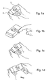
- the test device shown in Figure 1 comprises a housing 2 which houses a meter with a visible display 4, in this example, an LCD.
- a plunger 6 is released for use by the user pressing a release button which operates a catch.
- Figure 1a shows the device after a user has depressed the release button with his right index finger.
- the user partially depresses the plunger 6 to an intermediate position, causing a test strip to be presented for receiving a sample of blood ( Figure 1b).
- a reading is displayed on the display 4 ( Figure 1c).
- the user then fully depresses the plunger 6 so that it is again engaged by the catch, causing the test strip to be ejected.
- the device is then ready for another reading to be taken.
- Figure 1d illustrates the device after the test strip has been ejected and after the user has again pressed the release button to free the plunger 6. The various mechanisms involved in this process will be described below.
- a stack of test strips 8 is loaded in a magazine 10, which is in turn located in cavity 74 in a cartridge 12.
- spring means 14 in this example a helical spring.
- Each cavity has an opening 18 through which a test strip 8 will be pushed by a pusher 16.
- the spring urges the stack of test strips 8 upwards so that the top strip is engageable by the pusher 16.
- a foil seal 20 seals the cavities 74 containing the magazines 10. The slitting of the foil seal 20 will be described below, with reference to Figure 3, which shows progressive movement of the pusher 16.
- Advancement of the cartridge 12 moves it past a blade 22 which is mounted in the housing 2 of the test device.
- the blade 22 makes a slit in the foil seal 20 at one end, through which a test strip 8 is to be pushed.
- the pusher 16 is moved from one end of the cavity 74 to the other, as illustrated by positions (1) through (5) of Figure 3.
- cutting surfaces 24 on its leading edge cut the foil seal 20 and push the uppermost test strip 8 out through the opening 18 to the testing position (4) (corresponding to that shown in Figure 1b), where a test reading can be taken.
- Fully depressing the plunger 6 moves the pusher 16 further towards the opening 18 and ejects the test strip 8.
- the seal 20 is omitted for clarity.
- FIG 4 a mechanism is illustrated whereby movement of the pusher 16 from the position in Figure 4a initially pushes the test strip 8 out of the housing and then the head 28 of the pusher 16 bears down on the electrodes 26 of the meter so as to bring them into engagement with electrode tracks on the test strip 8 ( Figure 4b). After a reading has been taken, further advance of the pusher 16 ( Figure 4c) takes the head 28 beyond the electrodes 26, which disengage from the test strip 8 and permit the pusher 16 to eject the test strip.
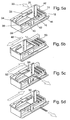
- the mechanism for advancing the pusher 16 is illustrated in Figure 5.
- the assembly shown in Figure 5 comprises a slider 32 which is operatively connected to the plunger 6.
- the slider 32 is slidably mounted on a chassis top 36 which receives a groove plate 34.
- the groove plate 34 has a groove therein which receives a sprung detent member 52 of the slider 32, the function of which will be described later.
- Also provided on the slider 32 is a ratchet driver 44 which engages with a ratchet wheel 40, the operation of which will be described later.
- a ratchet driver guide 38 is provided on the housing base 42.
- the back housing member 46 (and front housing member 64 - Figure 6) have cartridge tracks therein, along which the cartridge 12 can move.
- the ratchet driver 44 indexes the ratchet wheel by one position, and advances the cartridge 12 so that the foil 20 on the first magazine 10 is slit at one end.
- the user then pushes the slider 32 to an intermediate position ( Figure 5c) and in so doing, causes the pusher 16 to move back, with its cutting surfaces cutting the foil as previously described, and pushing the uppermost test strip out of the housing 2.
- the slider 32 is held in the intermediate position by engagement of the sprung detent member 52 in the groove of the groove plate 34.
- the detent member 52 and groove plate 34 operate in the manner of a ballpoint pen advancing and retracting mechanism, with the detent member 52 cycling around the groove in the course of one test cycle.
- Figure 6 shows some of the components more clearly, including the chassis cartridge end 70 which has a cartridge drive spring 68.
- a pusher "parking slot"plug 56 is mounted in the back housing member 46, where the pusher 16 is kept away from the cartridge 12 to permit movement of the cartridge.
- An optional sensor exit slot plug 66 is provided in the front housing member 64.
- a PCB 54 provides the meter electronics.
- a microprocessor on the PCB starts a timer counting down whereby the display 4 indicates when a particular magazine has exceeded its recommended life, or in the event that all magazines have exceeded their shelf life.
- FIG. 7 shows the cartridge advance mechanism as an exploded schematic, with the cartridge in half-section.
- the cartridge 12 is urged by the spring 68 in the direction of the arrow 72.
- Underneath the cartridge 12 there is provided a plurality of cartridge location pegs 76, which are spaced apart by the width of the magazines, ie the distance between the centre lines of the magazines 10.
- the ratchet wheel 40 has a keyway 78 thereon for the cartridge location pegs 76 to pass through as the cartridge 12 advances.
- the ratchet wheel is driven by the ratchet driver 44 which, cooperating with a pawl 62, drives the ratchet wheel 40 in a clockwise direction as viewed in Figure 7.
- the ratchet driver 44 reciprocates in both directions (80), but is sprung only in the direction indicated by the arrow 82.
- a cartridge final stop member 84 is provided at the proximal end of the housing base 42.
- Figures 8d through 8h shows the cartridge advancement sequence.
- the ratchet wheel 40 advances from the position shown in Figure 8e to that of Figure 8f, the two foremost location pegs 76 of cartridge 12 are freed to advance through the keyway 78.
- the location peg 76 furthest to the left in Figure 8f acts against the inclined surface of the keyway 78 while exiting the keyway.
- the rotation of the ratchet wheel 40 presents a solid stop wall at the point 88 to the oncoming location peg.
- the cartridge has advanced by one magazine width, and the location peg 76 of the magazine behind the new active magazine comes to rest against the ratchet wheel stop wall, aligning the next magazine ready for use.
- the front location peg 76 is located in the keyway 78 and the ratchet wheel 40 is located so that the first time the ratchet wheel is indexed, the foremost magazine 10 is advanced as describe above, and the seal is cut by the blade 22.
- the ratchet wheel is constructed to permit cartridge advance only once during a complete (360°) rotation.
- Figures 8i and 9a show how, with the ratchet wheel at position 10 (180° rotation), the cartridge 12 is prevented from premature advancement.
- the cartridge location peg 76 is prevented from entering the ratchet wheel keyway 78 through incorrect orientation and misalignment.
- the cartridge base 90 and location peg 76 are shown separated from the ratchet wheel in Figures 9a and 9b for clarity. With the ratchet wheel at position 11 ( Figures 8j and 9b) the location peg 76 is also misaligned with the ratchet keyway 78 and the cartridge does not advance.
- FIG. 10 An alternative embodiment is illustrated with respect to Figure 10.
- the magazines are releasably connected together, in this example by a dovetail joint (Figure 10b).
- Used magazines 10 project through an opening in the housing and can be removed by the user.
- Figure 10a shows plan views before (top) and after (bottom) a used magazine has been slid off from its neighbour.
- the housing can be made smaller because it need not accommodate used magazines.
- the test strip 8 shown in Figure 11 comprises a planar base member 92, in this example of poly(butylene terephthalate) (PBT) (Valox® FR-1 from GE Plastics).
- the strip is 30 mm x 5.5 mm, and 0.5 mm thick.
- a working area 94 is of conventional construction, comprising a plurality of electrodes, a reagent layer in intimate contact with the electrodes, and a mesh layer for spreading out a drop of fluid to be received on the working area.
- Electrode tracks 102, for example of carbon, in the non-working area 98 of the test strip are connected to the electrodes in the working area 94 in known manner.
- a dielectric layer 96 is printed around the working area 94 so as to overlie a portion of the electrode tracks 102, leaving just the ends of the tracks exposed for connection to corresponding 26 electrodes on the meter.
- the layers are applied to the base member as inks, by screen printing. Each ink layer is about 10 to 20 ⁇ m thick, and the mesh is about 59 to 67 ⁇ m thick.
- the working area 94 has a total thickness which is about 100 ⁇ m thicker than the non-working area 98 up to the dielectric layer 96.
- a high relief ink 100 has been printed in four strips.
- the high relief ink has a dried thickness such that the total thickness of the non-working area to which the high relief ink 100 has been applied is slightly greater than the total thickness of the test strip in the working area 94.
- the working area 94 will not bear all the compressive load. Scuffing of the test area will be reduced compared to a conventional test strip in which the working area stands proud of the non-working area.
- the ink could be printed as a continuous block, and it could entirely surround the working area if desired.
- other means could also be provided to increase the thickness of the non-working area, for example: an applied pad or tape; embossing of the base layer or an intermediate layer; or an extension of the mesh layer from the working area into the non-working area.
- test device for measuring blood glucose concentration
- the invention is not limited to this application.
- the invention may be used in the determination of any analyte in a fluid by the use of suitable reagents in the test strip.
- suitable reagents are well known to those skilled in the art.
Landscapes
- Health & Medical Sciences (AREA)
- Engineering & Computer Science (AREA)
- Biomedical Technology (AREA)
- Life Sciences & Earth Sciences (AREA)
- Physics & Mathematics (AREA)
- Chemical & Material Sciences (AREA)
- Medicinal Chemistry (AREA)
- General Health & Medical Sciences (AREA)
- Molecular Biology (AREA)
- Urology & Nephrology (AREA)
- Biophysics (AREA)
- Food Science & Technology (AREA)
- Optics & Photonics (AREA)
- Analytical Chemistry (AREA)
- Biochemistry (AREA)
- Hematology (AREA)
- General Physics & Mathematics (AREA)
- Immunology (AREA)
- Pathology (AREA)
- Investigating Or Analysing Biological Materials (AREA)
- Automatic Analysis And Handling Materials Therefor (AREA)
- Transition And Organic Metals Composition Catalysts For Addition Polymerization (AREA)
- Undergarments, Swaddling Clothes, Handkerchiefs Or Underwear Materials (AREA)
- Glass Compositions (AREA)
- Measurement Of The Respiration, Hearing Ability, Form, And Blood Characteristics Of Living Organisms (AREA)
- Investigating, Analyzing Materials By Fluorescence Or Luminescence (AREA)
Claims (15)
- Testvorrichtung zur Bestimmung der Analytkonzentration in einem darauf aufgetragenen Fluid, wobei die Vorrichtung aufweist:a) eine Vielzahl von Testgliedern (8), die in mindestens einem Stapel angeordnet sind, wobei jedes dieser Testglieder (8) Reagenzmittel zur Herstellung eines elektrischen Signals In Ansprechen auf die Analytkonzentration in einem aufgetragenen Fluid trägt und jedes dieser Testglieder (8) über eine Vielzahl von Elektrodenbahnen (102) zur Übermittlung dieses elektrischen Signals verfügt,b) ein Gehäuse (2) mit darin angeordneten Elektroden (26) zum in Eingriffkommen mit den Elektrodenbahnen auf einem Testglied (8) an einer Eingriffsposition,c) einen Zähler, der mit diesen Elektroden (26) verbunden und mindestens teilweise in dem Gehäuse (2) angeordnet ist sowie über elektronische Mittel (4) zur Herstellung eines Signaloutputs in Abhängigkeit von dem elektrischen Signal von einem Testglied (8), wenn das Testglied (8) mit den Elektroden (26) im Eingriff ist, verfügt,d) einen Ausstoßer (16), der ein einzelnes Testglied (8) aus einem Stapel zu der Eingriffsposition schieben kann, in der es mit den Elektroden (26) in Eingriff kommen kann und in der das Testglied (8) zum Auftragen eines Fluids darauf zugänglich ist,e) ein Betätigungsglied (6), das mit dem Ausstoßer (16) in Wirkverbindung steht, wobei das Betätigungsglied (6) von einem Benutzer zum Bewegen des Ausstoßers (16) betätigt werden kann,f) der oder jeder Stapel von Testgliedern (8) in einem Magazin (10) eingeschlossen ist, das ursprünglich durch ein feuchtigkeitsimpermeables Siegel (20) versiegelt ist,
gekennzeichnet durch,g) Schneidemittel (22), die in dem Gehäuse (2) zum Schlitzen des Siegels (20) befestigt sind undh) mindestens eine Schneidfläche (24) auf dem Ausstoßer (16) zum Schneiden des Siegels (20),i) wobei die Bewegung des oder jedes Magazins (10) von einer anfänglichen Position, in der das Siegel (20) unversehrt ist, zu einer Position, in der der Ausstoßer (16) ein Testglied (8) aus dem Stapel stoßen kann, das Schneidemittel (22) dazu bringt, das Siegel (20) unter Bildung eines Schlitzes zu schneiden, durch den ein Testglied (8) passieren kann, wenn es von dem Ausstoßer (16) gestoßen wird. - Vorrichtung nach Anspruch 1,
bei der die Testglieder (8) in einer Vielzahl von Stapeln angeordnet sind, jeden in einem Magazin (10) eingeschlossen ist, das anfänglich durch ein feuchtigkeitsimpermeables Siegel (20) versiegelt ist, die Magazine (10) derart bewegt werden können, dass sie das Schneidemittel (22) in die Lage versetzen, das Siegel (20) von jedem zu schlitzen, wenn das Magazin (10) eine Position erreicht, in der der Ausstoß (16) ein Testglied (8) daraus ausstoßen kann. - Vorrichtung nach Anspruch 1 oder 2,
bei der die Betätigung des Betätigungsgliedes (6) den Ausstoßer (16) dazu veranlasst, mit den Elektroden (26) in Eingriff zu kommen und sie in Kontakt mit den Elektrodenbahnen (102) auf dem Testglied (8) zu bringen, wenn das Testglied (8) in der Eingriffsposition ist. - Vorrichtung nach einem der vorhergehenden Ansprüche,
bei der die weitere Betätigung des Betätigungsgliedes (6) den Ausstoßer (16) dazu veranlasst, ein Testglied (8) aus der Eingriffsposition zu schieben und das Testglied (8) aus dem Gehäuse (2) herauszuschieben. - Vorrichtung nach Anspruch 2,
bei der das oder jedes Magazin (10) in einer Kartusche (12) untergebracht ist. - Vorrichtung nach Anspruch 5,
bei der die Kartusche (12) durch Federmittel (68) in Richtung eines Klinkenrades (40) bewegt wird, das eine darin angebrachte Keilnut (78) besitzt, die Kartusche (12) mit einer Vielzahl von voneinander beabstandeten Einrastzapfen (76) zum Einrasten in der Keilnut (78) ausgestattet ist und das Klinkenrad (40) nur dann den Eintritt des Einrastzapfens (76) erlaubt, wenn sich das Klinkenrad (40) in einer definierten Orientierung befindet. - Vorrichtung nach Anspruch 6,
bei der die Betätigung des Betätigungsgliedes (6) eine Schaltung des Klinkenrades (40) bewirkt. - Vorrichtung nach einem der vorhergehenden Ansprüche,
die außerdem ein Gleitelement (32) aufweist, das einen gewinkelten Schlitz (31) darin aufweist, der eine Mitnehmerfläche besitzt, welche gegen den Ausstoßer (16) anliegt, wobei eine Bewegung des Gleitelementes (32) in eine erste Richtung eine Bewegung des Ausstoßers (16) in eine zweite Richtung hervorruft. - Vorrichtung nach einem der vorhergehenden Ansprüche,
die außerdem Federmittel (14) aufweist, welche den Stapel von Testgliedern in Richtung des Siegels (20) zwingen. - Vorrichtung nach einem der vorhergehenden Ansprüche,
die außerdem Mittel (34, 52) aufweist, welche den Ausstoßer (16) lösbar zurückhalten, wenn sich das Testglied (18) in der Eingriffsposition befindet. - Vorrichtung nach einem der vorhergehenden Ansprüche,
die außerdem einen Prozessor und Mittel zum Starten eines Zeitmessers zu einem vorher bestimmten Zeitpunkt oder sobald ein Magazin zum ersten Mal geöffnet wird, aufweist, wobei der Prozessor derart programmiert ist, dass er eine sichtbare Warnung oder Nachricht bereitstellt, falls ein in Benutzung befindliches Magazin (10) seine Haltbarkeitszeit überschritten hat oder falls nicht geöffnete Magazine (10) ihre Haltbarkeitszeit überschritten haben. - Testvorrichtung nach einem der vorhergehenden Ansprüche,
bei der der zu testende Analyt Glukose ist und das aufzutragende Fluid Blut ist. - Testvorrichtung nach Anspruch 2,
bei der die Magazine (10) lösbar miteinander verbunden sind und bei der das Gehäuse (2) eine Öffnung besitzt, aus der verbrauchte Magazine (10) ausgestoßen werden. - Testvorrichtung nach einem der vorhergehenden Ansprüche,
bei der jedes Testglied (8) in dem oder jedem Stapel ein Basisglied (32) mit einer Arbeitszone (94), auf das das Fluid aufgetragen wird, welches die Reagenzmittel enthält, und eine Nicht-Arbeitszone (98) benachbart zu der Arbeitszone (94) aufweist und In der die Gesamtdicke der Testglieder (8) in mindestens einem Abschnitt der Nicht-Arbeitszone (98) mindestens so groß ist wie die Gesamtdicke des Testglieds (8) in der Arbeitszone (94). - Testvorrichtung nach Anspruch 14,
bei der die Gesamtdicke des Testglieds (8) in mindestens einem Teil der Nicht-Arbeitszone (98) größer ist als die Gesamtdicke des Testglieds (8) in der Arbeitszone (94).
Applications Claiming Priority (3)
| Application Number | Priority Date | Filing Date | Title |
|---|---|---|---|
| GBGB0017737.8A GB0017737D0 (en) | 2000-07-20 | 2000-07-20 | Test device |
| GB0017737 | 2000-07-20 | ||
| PCT/GB2001/003195 WO2002008753A2 (en) | 2000-07-20 | 2001-07-17 | Device for measuring analyte concentration in a fluid |
Publications (3)
| Publication Number | Publication Date |
|---|---|
| EP1301784A2 EP1301784A2 (de) | 2003-04-16 |
| EP1301784B1 true EP1301784B1 (de) | 2005-10-05 |
| EP1301784B8 EP1301784B8 (de) | 2006-03-15 |
Family
ID=9895963
Family Applications (1)
| Application Number | Title | Priority Date | Filing Date |
|---|---|---|---|
| EP01949722A Expired - Lifetime EP1301784B8 (de) | 2000-07-20 | 2001-07-17 | Vorrichtung zur messung der konzentration eines analyts in einer flüssigkeit |
Country Status (7)
| Country | Link |
|---|---|
| EP (1) | EP1301784B8 (de) |
| JP (1) | JP2004505244A (de) |
| AT (1) | ATE306081T1 (de) |
| AU (1) | AU2001270841A1 (de) |
| DE (1) | DE60113846T2 (de) |
| GB (1) | GB0017737D0 (de) |
| WO (1) | WO2002008753A2 (de) |
Families Citing this family (116)
| Publication number | Priority date | Publication date | Assignee | Title |
|---|---|---|---|---|
| US7235056B2 (en) | 1996-05-17 | 2007-06-26 | Amira Medical | Body fluid sampling device and methods of use |
| US7828749B2 (en) | 1996-05-17 | 2010-11-09 | Roche Diagnostics Operations, Inc. | Blood and interstitial fluid sampling device |
| US20020010406A1 (en) | 1996-05-17 | 2002-01-24 | Douglas Joel S. | Methods and apparatus for expressing body fluid from an incision |
| EP1579814A3 (de) | 1996-05-17 | 2006-06-14 | Roche Diagnostics Operations, Inc. | Verfahren und Vorrichtung zur Probenahme und Analyse von Körperflüssigkeit |
| US20050103624A1 (en) | 1999-10-04 | 2005-05-19 | Bhullar Raghbir S. | Biosensor and method of making |
| US8641644B2 (en) | 2000-11-21 | 2014-02-04 | Sanofi-Aventis Deutschland Gmbh | Blood testing apparatus having a rotatable cartridge with multiple lancing elements and testing means |
| US7537571B2 (en) | 2001-06-12 | 2009-05-26 | Pelikan Technologies, Inc. | Integrated blood sampling analysis system with multi-use sampling module |
| US9226699B2 (en) | 2002-04-19 | 2016-01-05 | Sanofi-Aventis Deutschland Gmbh | Body fluid sampling module with a continuous compression tissue interface surface |
| CA2448902C (en) | 2001-06-12 | 2010-09-07 | Pelikan Technologies, Inc. | Self optimizing lancing device with adaptation means to temporal variations in cutaneous properties |
| US7344507B2 (en) | 2002-04-19 | 2008-03-18 | Pelikan Technologies, Inc. | Method and apparatus for lancet actuation |
| US9427532B2 (en) | 2001-06-12 | 2016-08-30 | Sanofi-Aventis Deutschland Gmbh | Tissue penetration device |
| US9795747B2 (en) | 2010-06-02 | 2017-10-24 | Sanofi-Aventis Deutschland Gmbh | Methods and apparatus for lancet actuation |
| US7041068B2 (en) | 2001-06-12 | 2006-05-09 | Pelikan Technologies, Inc. | Sampling module device and method |
| US7279130B2 (en) * | 2001-08-13 | 2007-10-09 | Bayer Healthcare Llc | Sensor dispensing instrument having an activation mechanism and methods of using the same |
| US7344894B2 (en) | 2001-10-16 | 2008-03-18 | Agilent Technologies, Inc. | Thermal regulation of fluidic samples within a diagnostic cartridge |
| US6997343B2 (en) | 2001-11-14 | 2006-02-14 | Hypoguard Limited | Sensor dispensing device |
| CN101303346B (zh) | 2002-02-28 | 2012-10-03 | 爱科来株式会社 | 测量装置和动作机构 |
| CA2419905C (en) * | 2002-03-18 | 2016-01-05 | Bayer Healthcare, Llc | Storage cartridge for biosensors |
| GB2388898B (en) * | 2002-04-02 | 2005-10-05 | Inverness Medical Ltd | Integrated sample testing meter |
| US6881578B2 (en) | 2002-04-02 | 2005-04-19 | Lifescan, Inc. | Analyte concentration determination meters and methods of using the same |
| GB2390602A (en) * | 2002-04-02 | 2004-01-14 | Inverness Medical Ltd | Test strip dispenser vial and cassette |
| US7172728B2 (en) | 2002-04-02 | 2007-02-06 | Lifescan, Inc. | Test strip containers and methods of using the same |
| JP4143753B2 (ja) * | 2002-04-05 | 2008-09-03 | アークレイ株式会社 | 取り出し機構を備えた分析用具カートリッジ、およびこれと分析装置のセット |
| US8702624B2 (en) | 2006-09-29 | 2014-04-22 | Sanofi-Aventis Deutschland Gmbh | Analyte measurement device with a single shot actuator |
| US7901362B2 (en) | 2002-04-19 | 2011-03-08 | Pelikan Technologies, Inc. | Method and apparatus for penetrating tissue |
| US7244265B2 (en) | 2002-04-19 | 2007-07-17 | Pelikan Technologies, Inc. | Method and apparatus for penetrating tissue |
| US7648468B2 (en) | 2002-04-19 | 2010-01-19 | Pelikon Technologies, Inc. | Method and apparatus for penetrating tissue |
| US8784335B2 (en) | 2002-04-19 | 2014-07-22 | Sanofi-Aventis Deutschland Gmbh | Body fluid sampling device with a capacitive sensor |
| US7563232B2 (en) | 2002-04-19 | 2009-07-21 | Pelikan Technologies, Inc. | Method and apparatus for penetrating tissue |
| US8579831B2 (en) | 2002-04-19 | 2013-11-12 | Sanofi-Aventis Deutschland Gmbh | Method and apparatus for penetrating tissue |
| US7297122B2 (en) | 2002-04-19 | 2007-11-20 | Pelikan Technologies, Inc. | Method and apparatus for penetrating tissue |
| US7717863B2 (en) | 2002-04-19 | 2010-05-18 | Pelikan Technologies, Inc. | Method and apparatus for penetrating tissue |
| AU2003231749A1 (en) | 2002-04-19 | 2003-11-03 | Pelikan Technologies, Inc. | Device and method for variable speed lancet |
| US8267870B2 (en) | 2002-04-19 | 2012-09-18 | Sanofi-Aventis Deutschland Gmbh | Method and apparatus for body fluid sampling with hybrid actuation |
| US7371247B2 (en) | 2002-04-19 | 2008-05-13 | Pelikan Technologies, Inc | Method and apparatus for penetrating tissue |
| US7410468B2 (en) | 2002-04-19 | 2008-08-12 | Pelikan Technologies, Inc. | Method and apparatus for penetrating tissue |
| US9248267B2 (en) | 2002-04-19 | 2016-02-02 | Sanofi-Aventis Deustchland Gmbh | Tissue penetration device |
| US7524293B2 (en) | 2002-04-19 | 2009-04-28 | Pelikan Technologies, Inc. | Method and apparatus for penetrating tissue |
| US7485128B2 (en) | 2002-04-19 | 2009-02-03 | Pelikan Technologies, Inc. | Method and apparatus for penetrating tissue |
| US7226461B2 (en) | 2002-04-19 | 2007-06-05 | Pelikan Technologies, Inc. | Method and apparatus for a multi-use body fluid sampling device with sterility barrier release |
| US7491178B2 (en) | 2002-04-19 | 2009-02-17 | Pelikan Technologies, Inc. | Method and apparatus for penetrating tissue |
| US9314194B2 (en) | 2002-04-19 | 2016-04-19 | Sanofi-Aventis Deutschland Gmbh | Tissue penetration device |
| US9795334B2 (en) | 2002-04-19 | 2017-10-24 | Sanofi-Aventis Deutschland Gmbh | Method and apparatus for penetrating tissue |
| US7229458B2 (en) | 2002-04-19 | 2007-06-12 | Pelikan Technologies, Inc. | Method and apparatus for penetrating tissue |
| CN101173920B (zh) * | 2002-04-19 | 2012-04-18 | 松下电器产业株式会社 | 生物传感器盒及生物传感器分给装置 |
| US7291117B2 (en) | 2002-04-19 | 2007-11-06 | Pelikan Technologies, Inc. | Method and apparatus for penetrating tissue |
| US7374544B2 (en) | 2002-04-19 | 2008-05-20 | Pelikan Technologies, Inc. | Method and apparatus for penetrating tissue |
| US7547287B2 (en) | 2002-04-19 | 2009-06-16 | Pelikan Technologies, Inc. | Method and apparatus for penetrating tissue |
| US7232451B2 (en) | 2002-04-19 | 2007-06-19 | Pelikan Technologies, Inc. | Method and apparatus for penetrating tissue |
| US7331931B2 (en) | 2002-04-19 | 2008-02-19 | Pelikan Technologies, Inc. | Method and apparatus for penetrating tissue |
| US7141058B2 (en) | 2002-04-19 | 2006-11-28 | Pelikan Technologies, Inc. | Method and apparatus for a body fluid sampling device using illumination |
| US7674232B2 (en) | 2002-04-19 | 2010-03-09 | Pelikan Technologies, Inc. | Method and apparatus for penetrating tissue |
| US6945943B2 (en) | 2002-05-01 | 2005-09-20 | Lifescan, Inc. | Analyte concentration determination devices and methods of using the same |
| US7303726B2 (en) * | 2002-05-09 | 2007-12-04 | Lifescan, Inc. | Minimal procedure analyte test system |
| US7250095B2 (en) | 2002-07-11 | 2007-07-31 | Hypoguard Limited | Enzyme electrodes and method of manufacture |
| US8574895B2 (en) | 2002-12-30 | 2013-11-05 | Sanofi-Aventis Deutschland Gmbh | Method and apparatus using optical techniques to measure analyte levels |
| GB0300765D0 (en) * | 2003-01-14 | 2003-02-12 | Hypoguard Ltd | Sensor dispensing device |
| US7264139B2 (en) | 2003-01-14 | 2007-09-04 | Hypoguard Limited | Sensor dispensing device |
| WO2006001797A1 (en) | 2004-06-14 | 2006-01-05 | Pelikan Technologies, Inc. | Low pain penetrating |
| US7604592B2 (en) | 2003-06-13 | 2009-10-20 | Pelikan Technologies, Inc. | Method and apparatus for a point of care device |
| US7452457B2 (en) | 2003-06-20 | 2008-11-18 | Roche Diagnostics Operations, Inc. | System and method for analyte measurement using dose sufficiency electrodes |
| HUE039852T2 (hu) | 2003-06-20 | 2019-02-28 | Hoffmann La Roche | Eljárás és reagens keskeny, homogén reagenscsíkok elõállítására |
| US8206565B2 (en) | 2003-06-20 | 2012-06-26 | Roche Diagnostics Operation, Inc. | System and method for coding information on a biosensor test strip |
| US7645421B2 (en) | 2003-06-20 | 2010-01-12 | Roche Diagnostics Operations, Inc. | System and method for coding information on a biosensor test strip |
| US7645373B2 (en) | 2003-06-20 | 2010-01-12 | Roche Diagnostic Operations, Inc. | System and method for coding information on a biosensor test strip |
| US7597793B2 (en) | 2003-06-20 | 2009-10-06 | Roche Operations Ltd. | System and method for analyte measurement employing maximum dosing time delay |
| US7604721B2 (en) | 2003-06-20 | 2009-10-20 | Roche Diagnostics Operations, Inc. | System and method for coding information on a biosensor test strip |
| US8058077B2 (en) | 2003-06-20 | 2011-11-15 | Roche Diagnostics Operations, Inc. | Method for coding information on a biosensor test strip |
| US7718439B2 (en) | 2003-06-20 | 2010-05-18 | Roche Diagnostics Operations, Inc. | System and method for coding information on a biosensor test strip |
| US8148164B2 (en) | 2003-06-20 | 2012-04-03 | Roche Diagnostics Operations, Inc. | System and method for determining the concentration of an analyte in a sample fluid |
| US8071030B2 (en) | 2003-06-20 | 2011-12-06 | Roche Diagnostics Operations, Inc. | Test strip with flared sample receiving chamber |
| EP1671096A4 (de) | 2003-09-29 | 2009-09-16 | Pelikan Technologies Inc | Verfahren und apparatur für eine verbesserte probeneinfangvorrichtung |
| EP1680014A4 (de) | 2003-10-14 | 2009-01-21 | Pelikan Technologies Inc | Verfahren und gerät für eine variable anwenderschnittstelle |
| WO2005065414A2 (en) | 2003-12-31 | 2005-07-21 | Pelikan Technologies, Inc. | Method and apparatus for improving fluidic flow and sample capture |
| TWI440453B (zh) * | 2004-02-18 | 2014-06-11 | Universal Biosensors Pty Ltd | 試片排出系統 |
| WO2005109008A1 (ja) * | 2004-05-10 | 2005-11-17 | Arkray, Inc. | 分析装置 |
| US8828203B2 (en) | 2004-05-20 | 2014-09-09 | Sanofi-Aventis Deutschland Gmbh | Printable hydrogels for biosensors |
| US9775553B2 (en) | 2004-06-03 | 2017-10-03 | Sanofi-Aventis Deutschland Gmbh | Method and apparatus for a fluid sampling device |
| EP1765194A4 (de) | 2004-06-03 | 2010-09-29 | Pelikan Technologies Inc | Verfahren und gerät für eine flüssigkeitsentnahmenvorrichtung |
| US7582262B2 (en) | 2004-06-18 | 2009-09-01 | Roche Diagnostics Operations, Inc. | Dispenser for flattened articles |
| US7556723B2 (en) | 2004-06-18 | 2009-07-07 | Roche Diagnostics Operations, Inc. | Electrode design for biosensor |
| US7569126B2 (en) | 2004-06-18 | 2009-08-04 | Roche Diagnostics Operations, Inc. | System and method for quality assurance of a biosensor test strip |
| DE102004033317A1 (de) | 2004-07-09 | 2006-02-09 | Roche Diagnostics Gmbh | Analytisches Testelement |
| WO2006066123A1 (en) * | 2004-12-17 | 2006-06-22 | Bayer Healthcare Llc | Disposable test sensor cartridge |
| DE502005005709D1 (de) * | 2005-10-25 | 2008-11-27 | Roche Diagnostics Gmbh | Analysegerät zur Analyse einer Probe auf einem Testelement |
| DE102005062024B4 (de) * | 2005-12-22 | 2022-12-08 | Innovative Sensor Technology Ist Ag | Vorrichtung zur Ausgabe eines Sensorelements und Verfahren zur Herstellung eines Messgeräts |
| US7708702B2 (en) | 2006-01-26 | 2010-05-04 | Roche Diagnostics Operations, Inc. | Stack magazine system |
| US7638095B2 (en) * | 2006-02-10 | 2009-12-29 | Roche Diagnostics Operations, Inc. | Personal portable blood glucose meter with replaceable cartridge of test strips |
| US11559810B2 (en) | 2006-03-13 | 2023-01-24 | Trividia Health, Inc. | Method and apparatus for coding diagnostic meters |
| US8388906B2 (en) | 2006-03-13 | 2013-03-05 | Nipro Diagnostics, Inc. | Apparatus for dispensing test strips |
| US8388905B2 (en) | 2006-03-13 | 2013-03-05 | Nipro Diagnostics, Inc. | Method and apparatus for coding diagnostic meters |
| US8940246B2 (en) | 2006-03-13 | 2015-01-27 | Nipro Diagnostics, Inc. | Method and apparatus for coding diagnostic meters |
| US9052305B2 (en) * | 2007-03-06 | 2015-06-09 | Lifescan, Inc. | Test strip dispenser |
| EP2028488B1 (de) | 2007-08-02 | 2015-02-25 | F. Hoffmann-La Roche AG | Transfereinheit für Testelemente |
| US20090108013A1 (en) * | 2007-10-26 | 2009-04-30 | Martijn Nisse Van Der Velde | Test strip ejection mechanism |
| EP2265324B1 (de) | 2008-04-11 | 2015-01-28 | Sanofi-Aventis Deutschland GmbH | Integriertes System zur Messung von Analyten |
| US9375169B2 (en) | 2009-01-30 | 2016-06-28 | Sanofi-Aventis Deutschland Gmbh | Cam drive for managing disposable penetrating member actions with a single motor and motor and control system |
| KR101689890B1 (ko) | 2009-10-26 | 2016-12-26 | 아크레이 인코퍼레이티드 | 센서 카트리지 및 계측 장치 |
| TWM379061U (en) * | 2009-12-18 | 2010-04-21 | Ming-Hsiao Lai | Rejection structure of bio-sensing devices |
| DE102010016102B4 (de) * | 2010-03-23 | 2016-11-03 | Andreas Hettich Gmbh & Co. Kg | Messvorrichtung umfassend einen Resonator |
| US8965476B2 (en) | 2010-04-16 | 2015-02-24 | Sanofi-Aventis Deutschland Gmbh | Tissue penetration device |
| US9933409B2 (en) | 2011-11-15 | 2018-04-03 | Roche Diabetes Care, Inc. | Strip connector with reliable insertion and ejection |
| WO2013096268A1 (en) | 2011-12-20 | 2013-06-27 | Bayer Heal Thcare Llc | Linear, cartridge-based glucose measurement system |
| US9097700B2 (en) | 2011-12-29 | 2015-08-04 | Bayer Healthcare Llc | Glucose measurement system with high-capacity cartridge and capability of more frequent replenishment |
| GB2499838A (en) * | 2012-03-02 | 2013-09-04 | Smartsensor Telemed Ltd | Biological test device |
| SE536545C2 (sv) * | 2012-05-28 | 2014-02-11 | Melodia Medical Ab | Anordning vid en apparat för att mäta ämnen i kroppsvätskor |
| US9204829B2 (en) | 2012-05-31 | 2015-12-08 | Bayer Healthcare Llc | Multistrip cartridge |
| US9383333B2 (en) | 2012-05-31 | 2016-07-05 | Ascensia Diabetes Care Holdings Ag | Replaceable multistrip cartridge and biosensor meter |
| US8715571B2 (en) | 2012-06-29 | 2014-05-06 | Roche Diagnostics Operations, Inc. | Test strip ejector for medical device |
| US9039876B2 (en) | 2012-06-29 | 2015-05-26 | Roche Diagnostics Operations, Inc. | Test strip ejector for medical device |
| JP6136679B2 (ja) | 2012-08-09 | 2017-05-31 | 株式会社Gsユアサ | 蓄電装置及び電力経路開閉装置 |
| US9494569B2 (en) | 2013-02-07 | 2016-11-15 | Roche Diabetes Care, Inc. | Test strip ejector for medical device |
| US10533949B2 (en) | 2013-03-12 | 2020-01-14 | Ascensia Diabetes Care Holdings Ag | Test strip meter with a mechanism for pushing the test strip against an optical reader |
| EP3158329B1 (de) | 2014-06-19 | 2020-02-12 | Ascensia Diabetes Care Holdings AG | Sensorclip für sensorausgabesystem für gestapelte sensoren und zugehöriges system |
| CN105800126B (zh) * | 2016-05-10 | 2018-08-21 | 北京峰誉科技有限公司 | 一种应用于智能马桶的试纸盒及含有该试纸盒的智能马桶 |
| KR101993681B1 (ko) * | 2017-06-02 | 2019-06-28 | 주식회사 아이센스 | 일체형 혈당 측정기용 스트립 카트리지 |
Citations (1)
| Publication number | Priority date | Publication date | Assignee | Title |
|---|---|---|---|---|
| EP1271136A1 (de) * | 2000-02-23 | 2003-01-02 | ARKRAY, Inc. | Sensorkassette, sensor-zuführungseinrichtung und messinstrument |
Family Cites Families (3)
| Publication number | Priority date | Publication date | Assignee | Title |
|---|---|---|---|---|
| GB9223016D0 (en) * | 1992-11-03 | 1992-12-16 | Environmental And Medical Prod | Electrochemical sensor |
| US5630986A (en) * | 1995-01-13 | 1997-05-20 | Bayer Corporation | Dispensing instrument for fluid monitoring sensors |
| DE19639226B4 (de) * | 1996-09-24 | 2009-05-07 | Lre Technology Partner Gmbh | Tragbares Meßgerät zur Auswertung von Teststreifen |
-
2000
- 2000-07-20 GB GBGB0017737.8A patent/GB0017737D0/en not_active Ceased
-
2001
- 2001-07-17 DE DE60113846T patent/DE60113846T2/de not_active Expired - Fee Related
- 2001-07-17 AU AU2001270841A patent/AU2001270841A1/en not_active Abandoned
- 2001-07-17 EP EP01949722A patent/EP1301784B8/de not_active Expired - Lifetime
- 2001-07-17 WO PCT/GB2001/003195 patent/WO2002008753A2/en not_active Ceased
- 2001-07-17 JP JP2002514396A patent/JP2004505244A/ja active Pending
- 2001-07-17 AT AT01949722T patent/ATE306081T1/de not_active IP Right Cessation
Patent Citations (1)
| Publication number | Priority date | Publication date | Assignee | Title |
|---|---|---|---|---|
| EP1271136A1 (de) * | 2000-02-23 | 2003-01-02 | ARKRAY, Inc. | Sensorkassette, sensor-zuführungseinrichtung und messinstrument |
Also Published As
| Publication number | Publication date |
|---|---|
| DE60113846T2 (de) | 2006-04-27 |
| GB0017737D0 (en) | 2000-09-06 |
| EP1301784B8 (de) | 2006-03-15 |
| JP2004505244A (ja) | 2004-02-19 |
| ATE306081T1 (de) | 2005-10-15 |
| DE60113846D1 (de) | 2005-11-10 |
| EP1301784A2 (de) | 2003-04-16 |
| WO2002008753A2 (en) | 2002-01-31 |
| AU2001270841A1 (en) | 2002-02-05 |
| WO2002008753A3 (en) | 2002-04-18 |
Similar Documents
| Publication | Publication Date | Title |
|---|---|---|
| US7138089B2 (en) | Test device for analyzing blood glucose or other analytes in bodily fluids | |
| EP1301784A2 (de) | Vorrichtung zur messung der konzentration eines analyts in einer flüssigkeit | |
| EP1314029B1 (de) | Vorrichtung zur konzentrationsmessung für ein analyt in einer flüssigkeit | |
| EP1362551B1 (de) | Analysegerät mit minimalem Handhabungsaufwand | |
| EP0922959B1 (de) | Analysensystem für Probenflüssigkeiten | |
| US20020057993A1 (en) | Test device | |
| US6997344B2 (en) | Automated mechanical mechanism for a blood glucose sensor dispensing instrument | |
| US8777872B2 (en) | Diagnostic system for determining substance concentrations in liquid samples | |
| CA2618973C (en) | Integrated test system for monitoring bodily fluids | |
| US8509870B2 (en) | Analyte test device | |
| EP1869456B1 (de) | Sensorabgabegeräte | |
| AU2007300034A1 (en) | Integrated sensor for analyzing biological samples | |
| WO2008039946A2 (en) | Integrated meter for analyzing biological samples | |
| EP1875231B1 (de) | Einweg-testsensorkassette | |
| US8101126B2 (en) | Sensor release mechanism for a meter | |
| EP2769215A1 (de) | Kartusche und dosierungsvorrichtung für flüssigkeitsteststreifen | |
| EP1877780A1 (de) | Sensorfreisetzungsmechanismus für testmessgerät | |
| HK1172533A1 (en) | Body fluid lancing, acquiring, and testing cartridge design | |
| HK1172533B (en) | Body fluid lancing, acquiring, and testing cartridge design | |
| HK1125016B (en) | Minimal procedure analyte test system |
Legal Events
| Date | Code | Title | Description |
|---|---|---|---|
| PUAI | Public reference made under article 153(3) epc to a published international application that has entered the european phase |
Free format text: ORIGINAL CODE: 0009012 |
|
| 17P | Request for examination filed |
Effective date: 20021204 |
|
| AK | Designated contracting states |
Designated state(s): AT BE CH CY DE DK ES FI FR GB GR IE IT LI LU MC NL PT SE TR |
|
| AX | Request for extension of the european patent |
Extension state: AL LT LV MK RO SI |
|
| RIN1 | Information on inventor provided before grant (corrected) |
Inventor name: MAY, STUART RICHARD Inventor name: BLACK, MURDO M. Inventor name: WOODHEAD, ANDREW JAMES |
|
| 17Q | First examination report despatched |
Effective date: 20040728 |
|
| GRAP | Despatch of communication of intention to grant a patent |
Free format text: ORIGINAL CODE: EPIDOSNIGR1 |
|
| GRAS | Grant fee paid |
Free format text: ORIGINAL CODE: EPIDOSNIGR3 |
|
| GRAA | (expected) grant |
Free format text: ORIGINAL CODE: 0009210 |
|
| AK | Designated contracting states |
Kind code of ref document: B1 Designated state(s): AT BE CH CY DE DK ES FI FR GB GR IE IT LI LU MC NL PT SE TR |
|
| PG25 | Lapsed in a contracting state [announced via postgrant information from national office to epo] |
Ref country code: FI Free format text: LAPSE BECAUSE OF FAILURE TO SUBMIT A TRANSLATION OF THE DESCRIPTION OR TO PAY THE FEE WITHIN THE PRESCRIBED TIME-LIMIT Effective date: 20051005 Ref country code: AT Free format text: LAPSE BECAUSE OF FAILURE TO SUBMIT A TRANSLATION OF THE DESCRIPTION OR TO PAY THE FEE WITHIN THE PRESCRIBED TIME-LIMIT Effective date: 20051005 Ref country code: NL Free format text: LAPSE BECAUSE OF FAILURE TO SUBMIT A TRANSLATION OF THE DESCRIPTION OR TO PAY THE FEE WITHIN THE PRESCRIBED TIME-LIMIT Effective date: 20051005 Ref country code: BE Free format text: LAPSE BECAUSE OF FAILURE TO SUBMIT A TRANSLATION OF THE DESCRIPTION OR TO PAY THE FEE WITHIN THE PRESCRIBED TIME-LIMIT Effective date: 20051005 Ref country code: LI Free format text: LAPSE BECAUSE OF FAILURE TO SUBMIT A TRANSLATION OF THE DESCRIPTION OR TO PAY THE FEE WITHIN THE PRESCRIBED TIME-LIMIT Effective date: 20051005 Ref country code: CH Free format text: LAPSE BECAUSE OF FAILURE TO SUBMIT A TRANSLATION OF THE DESCRIPTION OR TO PAY THE FEE WITHIN THE PRESCRIBED TIME-LIMIT Effective date: 20051005 |
|
| REG | Reference to a national code |
Ref country code: GB Ref legal event code: FG4D |
|
| REG | Reference to a national code |
Ref country code: CH Ref legal event code: EP |
|
| REG | Reference to a national code |
Ref country code: IE Ref legal event code: FG4D |
|
| REF | Corresponds to: |
Ref document number: 60113846 Country of ref document: DE Date of ref document: 20051110 Kind code of ref document: P |
|
| RIN2 | Information on inventor provided after grant (corrected) |
Inventor name: BLACK, MURDO M. Inventor name: WOODHEAD, ANDREW JAMES Inventor name: MAY, STUART RICHARD Inventor name: AITKEN, JAMES |
|
| PG25 | Lapsed in a contracting state [announced via postgrant information from national office to epo] |
Ref country code: SE Free format text: LAPSE BECAUSE OF FAILURE TO SUBMIT A TRANSLATION OF THE DESCRIPTION OR TO PAY THE FEE WITHIN THE PRESCRIBED TIME-LIMIT Effective date: 20060105 Ref country code: DK Free format text: LAPSE BECAUSE OF FAILURE TO SUBMIT A TRANSLATION OF THE DESCRIPTION OR TO PAY THE FEE WITHIN THE PRESCRIBED TIME-LIMIT Effective date: 20060105 Ref country code: GR Free format text: LAPSE BECAUSE OF FAILURE TO SUBMIT A TRANSLATION OF THE DESCRIPTION OR TO PAY THE FEE WITHIN THE PRESCRIBED TIME-LIMIT Effective date: 20060105 |
|
| PG25 | Lapsed in a contracting state [announced via postgrant information from national office to epo] |
Ref country code: ES Free format text: LAPSE BECAUSE OF FAILURE TO SUBMIT A TRANSLATION OF THE DESCRIPTION OR TO PAY THE FEE WITHIN THE PRESCRIBED TIME-LIMIT Effective date: 20060116 |
|
| NLV1 | Nl: lapsed or annulled due to failure to fulfill the requirements of art. 29p and 29m of the patents act | ||
| PG25 | Lapsed in a contracting state [announced via postgrant information from national office to epo] |
Ref country code: PT Free format text: LAPSE BECAUSE OF FAILURE TO SUBMIT A TRANSLATION OF THE DESCRIPTION OR TO PAY THE FEE WITHIN THE PRESCRIBED TIME-LIMIT Effective date: 20060306 |
|
| RIN2 | Information on inventor provided after grant (corrected) |
Inventor name: BLACK, MURDO M. Inventor name: MAY, STUART RICHARD Inventor name: AITKEN, JAMES Inventor name: WOODHEAD, ANDREW JAMES |
|
| REG | Reference to a national code |
Ref country code: CH Ref legal event code: PL |
|
| ET | Fr: translation filed | ||
| PG25 | Lapsed in a contracting state [announced via postgrant information from national office to epo] |
Ref country code: IE Free format text: LAPSE BECAUSE OF NON-PAYMENT OF DUE FEES Effective date: 20060717 |
|
| PGFP | Annual fee paid to national office [announced via postgrant information from national office to epo] |
Ref country code: FR Payment date: 20060726 Year of fee payment: 6 |
|
| PG25 | Lapsed in a contracting state [announced via postgrant information from national office to epo] |
Ref country code: MC Free format text: LAPSE BECAUSE OF NON-PAYMENT OF DUE FEES Effective date: 20060731 |
|
| PGFP | Annual fee paid to national office [announced via postgrant information from national office to epo] |
Ref country code: GB Payment date: 20060731 Year of fee payment: 6 Ref country code: IT Payment date: 20060731 Year of fee payment: 6 |
|
| PLBE | No opposition filed within time limit |
Free format text: ORIGINAL CODE: 0009261 |
|
| STAA | Information on the status of an ep patent application or granted ep patent |
Free format text: STATUS: NO OPPOSITION FILED WITHIN TIME LIMIT |
|
| 26N | No opposition filed |
Effective date: 20060706 |
|
| PGFP | Annual fee paid to national office [announced via postgrant information from national office to epo] |
Ref country code: DE Payment date: 20060915 Year of fee payment: 6 |
|
| REG | Reference to a national code |
Ref country code: IE Ref legal event code: MM4A |
|
| GBPC | Gb: european patent ceased through non-payment of renewal fee |
Effective date: 20070717 |
|
| PG25 | Lapsed in a contracting state [announced via postgrant information from national office to epo] |
Ref country code: DE Free format text: LAPSE BECAUSE OF NON-PAYMENT OF DUE FEES Effective date: 20080201 |
|
| PG25 | Lapsed in a contracting state [announced via postgrant information from national office to epo] |
Ref country code: GB Free format text: LAPSE BECAUSE OF NON-PAYMENT OF DUE FEES Effective date: 20070717 |
|
| REG | Reference to a national code |
Ref country code: FR Ref legal event code: ST Effective date: 20080331 |
|
| PG25 | Lapsed in a contracting state [announced via postgrant information from national office to epo] |
Ref country code: LU Free format text: LAPSE BECAUSE OF NON-PAYMENT OF DUE FEES Effective date: 20060717 Ref country code: TR Free format text: LAPSE BECAUSE OF FAILURE TO SUBMIT A TRANSLATION OF THE DESCRIPTION OR TO PAY THE FEE WITHIN THE PRESCRIBED TIME-LIMIT Effective date: 20051005 |
|
| PG25 | Lapsed in a contracting state [announced via postgrant information from national office to epo] |
Ref country code: FR Free format text: LAPSE BECAUSE OF NON-PAYMENT OF DUE FEES Effective date: 20070731 |
|
| PG25 | Lapsed in a contracting state [announced via postgrant information from national office to epo] |
Ref country code: CY Free format text: LAPSE BECAUSE OF FAILURE TO SUBMIT A TRANSLATION OF THE DESCRIPTION OR TO PAY THE FEE WITHIN THE PRESCRIBED TIME-LIMIT Effective date: 20051005 |
|
| PG25 | Lapsed in a contracting state [announced via postgrant information from national office to epo] |
Ref country code: IT Free format text: LAPSE BECAUSE OF NON-PAYMENT OF DUE FEES Effective date: 20070717 |