EP1300644A2 - Wärmeübertrager und Verfahren zu seiner Herstellung - Google Patents
Wärmeübertrager und Verfahren zu seiner Herstellung Download PDFInfo
- Publication number
- EP1300644A2 EP1300644A2 EP02020117A EP02020117A EP1300644A2 EP 1300644 A2 EP1300644 A2 EP 1300644A2 EP 02020117 A EP02020117 A EP 02020117A EP 02020117 A EP02020117 A EP 02020117A EP 1300644 A2 EP1300644 A2 EP 1300644A2
- Authority
- EP
- European Patent Office
- Prior art keywords
- heat exchanger
- channel
- flat tubes
- exchanger according
- edges
- Prior art date
- Legal status (The legal status is an assumption and is not a legal conclusion. Google has not performed a legal analysis and makes no representation as to the accuracy of the status listed.)
- Withdrawn
Links
Images


Classifications
-
- F—MECHANICAL ENGINEERING; LIGHTING; HEATING; WEAPONS; BLASTING
- F28—HEAT EXCHANGE IN GENERAL
- F28F—DETAILS OF HEAT-EXCHANGE AND HEAT-TRANSFER APPARATUS, OF GENERAL APPLICATION
- F28F9/00—Casings; Header boxes; Auxiliary supports for elements; Auxiliary members within casings
- F28F9/02—Header boxes; End plates
- F28F9/04—Arrangements for sealing elements into header boxes or end plates
- F28F9/16—Arrangements for sealing elements into header boxes or end plates by permanent joints, e.g. by rolling
- F28F9/18—Arrangements for sealing elements into header boxes or end plates by permanent joints, e.g. by rolling by welding
- F28F9/182—Arrangements for sealing elements into header boxes or end plates by permanent joints, e.g. by rolling by welding the heat-exchange conduits having ends with a particular shape, e.g. deformed; the heat-exchange conduits or end plates having supplementary joining means, e.g. abutments
-
- F—MECHANICAL ENGINEERING; LIGHTING; HEATING; WEAPONS; BLASTING
- F28—HEAT EXCHANGE IN GENERAL
- F28D—HEAT-EXCHANGE APPARATUS, NOT PROVIDED FOR IN ANOTHER SUBCLASS, IN WHICH THE HEAT-EXCHANGE MEDIA DO NOT COME INTO DIRECT CONTACT
- F28D1/00—Heat-exchange apparatus having stationary conduit assemblies for one heat-exchange medium only, the media being in contact with different sides of the conduit wall, in which the other heat-exchange medium is a large body of fluid, e.g. domestic or motor car radiators
- F28D1/02—Heat-exchange apparatus having stationary conduit assemblies for one heat-exchange medium only, the media being in contact with different sides of the conduit wall, in which the other heat-exchange medium is a large body of fluid, e.g. domestic or motor car radiators with heat-exchange conduits immersed in the body of fluid
- F28D1/04—Heat-exchange apparatus having stationary conduit assemblies for one heat-exchange medium only, the media being in contact with different sides of the conduit wall, in which the other heat-exchange medium is a large body of fluid, e.g. domestic or motor car radiators with heat-exchange conduits immersed in the body of fluid with tubular conduits
- F28D1/047—Heat-exchange apparatus having stationary conduit assemblies for one heat-exchange medium only, the media being in contact with different sides of the conduit wall, in which the other heat-exchange medium is a large body of fluid, e.g. domestic or motor car radiators with heat-exchange conduits immersed in the body of fluid with tubular conduits the conduits being bent, e.g. in a serpentine or zig-zag
- F28D1/0477—Heat-exchange apparatus having stationary conduit assemblies for one heat-exchange medium only, the media being in contact with different sides of the conduit wall, in which the other heat-exchange medium is a large body of fluid, e.g. domestic or motor car radiators with heat-exchange conduits immersed in the body of fluid with tubular conduits the conduits being bent, e.g. in a serpentine or zig-zag the conduits being bent in a serpentine or zig-zag
- F28D1/0478—Heat-exchange apparatus having stationary conduit assemblies for one heat-exchange medium only, the media being in contact with different sides of the conduit wall, in which the other heat-exchange medium is a large body of fluid, e.g. domestic or motor car radiators with heat-exchange conduits immersed in the body of fluid with tubular conduits the conduits being bent, e.g. in a serpentine or zig-zag the conduits being bent in a serpentine or zig-zag the conduits having a non-circular cross-section
-
- F—MECHANICAL ENGINEERING; LIGHTING; HEATING; WEAPONS; BLASTING
- F28—HEAT EXCHANGE IN GENERAL
- F28F—DETAILS OF HEAT-EXCHANGE AND HEAT-TRANSFER APPARATUS, OF GENERAL APPLICATION
- F28F1/00—Tubular elements; Assemblies of tubular elements
- F28F1/02—Tubular elements of cross-section which is non-circular
- F28F1/025—Tubular elements of cross-section which is non-circular with variable shape, e.g. with modified tube ends, with different geometrical features
-
- F—MECHANICAL ENGINEERING; LIGHTING; HEATING; WEAPONS; BLASTING
- F28—HEAT EXCHANGE IN GENERAL
- F28F—DETAILS OF HEAT-EXCHANGE AND HEAT-TRANSFER APPARATUS, OF GENERAL APPLICATION
- F28F9/00—Casings; Header boxes; Auxiliary supports for elements; Auxiliary members within casings
- F28F9/02—Header boxes; End plates
- F28F9/0202—Header boxes having their inner space divided by partitions
- F28F9/0204—Header boxes having their inner space divided by partitions for elongated header box, e.g. with transversal and longitudinal partitions
- F28F9/0209—Header boxes having their inner space divided by partitions for elongated header box, e.g. with transversal and longitudinal partitions having only transversal partitions
- F28F9/0212—Header boxes having their inner space divided by partitions for elongated header box, e.g. with transversal and longitudinal partitions having only transversal partitions the partitions being separate elements attached to header boxes
-
- F—MECHANICAL ENGINEERING; LIGHTING; HEATING; WEAPONS; BLASTING
- F28—HEAT EXCHANGE IN GENERAL
- F28F—DETAILS OF HEAT-EXCHANGE AND HEAT-TRANSFER APPARATUS, OF GENERAL APPLICATION
- F28F9/00—Casings; Header boxes; Auxiliary supports for elements; Auxiliary members within casings
- F28F9/02—Header boxes; End plates
- F28F9/0219—Arrangements for sealing end plates into casing or header box; Header box sub-elements
- F28F9/0221—Header boxes or end plates formed by stacked elements
-
- F—MECHANICAL ENGINEERING; LIGHTING; HEATING; WEAPONS; BLASTING
- F28—HEAT EXCHANGE IN GENERAL
- F28F—DETAILS OF HEAT-EXCHANGE AND HEAT-TRANSFER APPARATUS, OF GENERAL APPLICATION
- F28F9/00—Casings; Header boxes; Auxiliary supports for elements; Auxiliary members within casings
- F28F9/02—Header boxes; End plates
- F28F9/0243—Header boxes having a circular cross-section
Definitions
- the invention relates to a heat exchanger, in particular for a CO 2 circuit, with a collecting tube which serves to act on a plurality of tubes or flat tubes with a medium involved in the heat transfer.
- the invention also relates to a method for producing such a heat exchanger with at least one collecting tube.
- Collecting boxes of this type are known for example from DE 40 28 438 A1 known. It is also known (DE 37 01 865 A1), a manifold directly through the juxtaposed flared ends of Flat tubes or the like to form or prefabricated pipes as Use manifolds that are machined with openings be provided for insertion of the flat tube ends (DE 199 45 223 A1).
- the manufacturing cost of such headers is because of the necessary editing very big, to that comes before the soldering about any remaining chips are carefully removed In order to prevent leaks due to unwanted burring in the avoid later soldering. There is also the danger that Chips lead to malfunctions of the refrigerant circuit.
- the present invention is therefore based on the object, a Heat exchanger with a manifold so that he in easy way to produce and also in a simple way with flat tubes can be equipped.
- This configuration makes it possible in a simple manner without any Machining, flat tubes with each other through the Connecting collecting tube, wherein the gap shaped edges for form the soldering process suitable contact surfaces on the flat tube ends.
- the metal strip on its inside be soldered, if he, what will be discussed, from a Flat material is formed.
- This embodiment also offers the possibility to simplify the soldering process.
- the edges of the metal strip diverge outwards and so an insertion bevel for the flat tubes form, which greatly facilitates the assembly process.
- the cross section the gutter can correspond to an omega in a particularly simple way. It results in a stable cross-section, which is also particularly simply suitable for insertion of the flat tube ends. It can the closed area of the gutter with incisions for insertion of Be provided with separating or end walls and also with openings, which can serve as inflow or outflow opening for the medium.
- the Omegaquerites correspond and in Let slide longitudinally onto the gutters, so that the arrangement incisions, optionally retrospectively in the manifold must be provided, is not necessary, and the at the same time the space between ribs and supply pipes against misguided air block. It will be shown later, however, that Such incisions or openings even before the transformation of the BlechstMails introduced to its channel shape by punching so that even then a machining can not is required.
- the flat tubes can be twisted by 90 ° Ends are inserted into the gap, with the twisted ones Ends of several flat tubes in the interior of the channel directly to each other abut and so set the distance of the individual flat tubes.
- the flat tubes are each chosen from the free end so that the twisted Part immediately as a stop at the edges forming the gap can serve. Also towards the axis of the gutter is on this Way an alignment of the flat tubes possible without separate Measures must be taken.
- the production the collection tube to provide a method in which as the starting material a flattened on at least one side soldered flat Sheet metal strip is provided, with the solder-plated side inside is bent to the groove, the edges of at least one Make a distance to each other, the one on the strength of forms a split gap to be inserted flat tubes.
- Such Production also makes it possible in a simple manner, in the first to provide even flat sheet metal stampings, which after the forming of such a metal strip to its final form, which for example, in a multi-stage or progressive composite press tool can happen, the incisions for inserting the separation or End walls or the inflow and outflow openings for the medium form.
- the embodiment can also be made in such a way that after inserting the free flat tube ends in the gap between the edges the later solder joint a certain distance to the flat tube end, thereby avoiding that Lot flows into the flat tube channels by capillary forces.
- the preparation of can also be used before the soldering process for Dichtlötung between the flat tubes still a solder foil or a thin solder coated sheet inserted become.
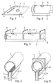
- a piece of a flat sheet metal strip 1 ' is shown, the for producing a manifold according to the present invention is provided.
- This sheet metal strip 1 ' is with a slot-shaped Punching 2 and with a round also punched-out opening 3 Provided.
- the metal strip 1 ' is facing away from the viewer Bottom lotplattiert in a manner not shown.
- This Channel can, for example, the cross-sectional shape of FIG. 4, and it has one-sided protruding, mutually approximately parallel edges 5, which form between them a gap 6 (see also Fig. 3), the is exploited to the ends of a flat tube 7 - Fig. 4 - record. These ends 7 'are only slightly over the narrowest point of the Slit 6 upwards.
- the ends 7 'of Flat tubes 7 are soldered to the edges 5, so that a dense Can accommodate flat tubes, without a manifold provided with insertion openings by mechanical processing must become.
- the ends or at least one end of a gutter may be at least one Bevel 20 in the direction of the inserted flat tubes, the serve as insertion aid for the flat tubes.
- FIGS. 3 and 5 make it clear that the channel 1 is relatively simple Way a collection tube can be formed when partitions 8 divide different sections of the channel against each other and for example one of the openings 3 as an inflow opening to the manifold flows in the direction of the arrow 9 and another opening 3 in another portion of the manifold as a drain opening to the outflow used in the direction of arrow 10.
- the partitions 8 are inserted into the slot openings 2, which are so dimensioned are that the lowest point of the slot 2 in the final shape of the channel. 2 according to Fig. 3 or Fig. 5 with the beginning of the end 7 'of the flat tube coincides.
- the partition 8 for example, as a solder-plated flat sheet is formed, can then be inserted into the slot 2 and then soldered in the channel 1, wherein the flat tubes 7 with the edges 5 of the gutter are soldered tight, so that a Heat exchanger can be formed, the flat tubes in not be shown in detail by one of the media to be flown, the participates in heat transfer while the second medium through the manifold, i. through the channel 1 and through the flat tubes 7 flows.
- the partitions preferably have cutouts 21, which can at least partially take the pipes.
- Fig. 6 shows a variant of a heat exchanger in so far as here Flat tubes 11 inserted into the groove formed as a collecting channel 1 are, whose inserted between the edges 5 ends 11 'respectively are rotated by 90 ° relative to the rest of the pipe section.
- the flat tubes 11 are flowed through in the direction of the arrow 12.
- partitions 8 in its length divide and provided with inflow or outflow 3, as the was explained with reference to FIGS. 1 to 5.
- the production of the gutter 1 is also done in the same way.
- FIG. 7 shows in this context that the in the Trough 1 inserted ends 11 'of the flat tubes 11 in abutment lie and so does the distance between the individual flat tubes 11 can be met in a simple manner.
- FIG. 8 shows a variant of the collecting tube designed as a channel insofar as here the edges 5a diverge outwards and only lie in an area on the flat tubes 7, something of the free End of the edge is removed.
- the edges 5a form in this way in each case an insertion bevel for the free ends of the flat tubes. 7
- the engagement or insertion depth The pipes limited because by turning the pipe ends the Width of the pipe ends with increasing distance from the pipe end grows. The soldering takes place in the contact area of the edges 5a with the Flat tubes 7 instead.
- Figs. 9 to 12 illustrate another way of attaching End walls for the trained as a gutter 1 collection tube.
- Be lotplattator plates 13 with a recess 16 in the cross-sectional shape made the channel 1, which then after the flat tube 14 or more flat tubes are inserted into the channel, from the outside be pushed onto the channel 1, until they on the or abut the flat tubes. In this position, the sheets 13 are then soldered together with the flat tube and the channel 1.
- This embodiment also opens up the possibility of several such To arrange recesses 16 in a common plate 15, the then, as shown in FIG. 12, as a side plate of three side by side lying collecting pipes in the form of grooves 1 is usable and For example, the production of a serpentine heat exchanger with in loops laid flat tubes 17 and 18 allows.
- Figure 12 also shows a cover strip 22, which serves to that as little false air is generated.
Landscapes
- Engineering & Computer Science (AREA)
- Physics & Mathematics (AREA)
- Thermal Sciences (AREA)
- Mechanical Engineering (AREA)
- General Engineering & Computer Science (AREA)
- Geometry (AREA)
- Details Of Heat-Exchange And Heat-Transfer (AREA)
- Heat-Exchange Devices With Radiators And Conduit Assemblies (AREA)
Abstract
Description
- Fig. 1
- einen Teil eines zur Herstellung eines Sammelrohrs vorgesehenen flachen Blechstreifen,
- Fig. 2
- einen Abschnitt des aus dem Blechstreifen durch Umbiegen gebildeten Sammelrohres,
- Fig. 3
- das durch eingesetzte Trennwände in einen Zu- und in einen Abführabschnitt unterteilte Sammelrohr,
- Fig. 4
- eine perspektivische Darstellung eines Sammelrohrendes im noch nicht verschlossenen Zustand mit einem eingesetzten Sammelrohr,
- Fig. 5
- eine Darstellung ähnlich Fig. 4, jedoch mit einer eingesetzten Trennwand,
- Fig. 6
- eine Darstellung ähnlich Fig. 4, jedoch mit mehreren eingesetzten Flachrohren, deren Enden um 90° gegenüber den anderen Abschnitten verdreht sind,
- Fig. 7
- einen schematischen Längsschnitt durch einen Wärmeübertrager nach Fig. 6 mit eingesetzten Flachrohren,
- Fig. 8
- ein Sammelrohr ähnlich Fig. 4, jedoch mit einem Omegaquerschnitt zur Bildung einer Einführschräge,
- Fig. 9
- eine schematische Seitenansicht eines Teiles eines Wärmeübertragers, bei dem ein Sammelrohrquerschnitt nach Fig. 8 vorgesehen ist,
- Fig. 10
- die Ansicht eines der als Abschlusswand vorgesehenen Bleche der Fig. 9,
- Fig. 11
- eine Trennwand ähnlich Fig. 10, jedoch mit mehreren Aussparungen zur Nebeneinanderanordnung mehrerer Sammelrohre und
- Fig. 12
- ein Ausführungsbeispiel eines Wärmeübertragers mit mehreren nebeneinander liegenden Sammelrohren und einer Rohrausbildung in Serpentinenform.
Claims (19)
- Wärmeübertrager mit einem Sammelrohr, insbesondere für einen CO2 Kreislauf, das zur Beaufschlagung mehrerer Flachrohre mit einem an der Wärmeübertragung beteiligten Medium dient, wobei das Sammelrohr gekennzeichnet ist durch einen zu einer Rinne geformten Blechstreifen, dessen Ränder im wesentlichen parallel zu einer Längsmittelebene der Rinne verlaufen und einen offenen Spalt bilden, der zur Aufnahme der freien Enden der Flachrohre dient.
- Wärmeübertrager nach Anspruch 1, dadurch gekennzeichnet, daß die Ränder der Rinne einen Winkel α zwischen 0 und 90 Grad einschließen.
- Wärmeübertrager nach einem der vorhergehenden Ansprüche, dadurch gekennzeichnet, daß an zumindest einem der Ränder der Rinne an einem Endbereich eine Fase angeordnet ist.
- Wärmeübertrager nach Anspruch 1, 2 oder 3, dadurch gekennzeichnet, dass der Blechstreifen auf seiner Innenseite lotplattiert ist.
- Wärmeübertrager nach Anspruch 1, 2, 3 oder 4, dadurch gekennzeichnet, dass die Ränder des zur Rinne geformten Blechstreifens nach außen divergieren und eine Einführschräge für die Flachrohre bilden.
- Wärmeübertrager nach einem vorhergehenden Anspruch, dadurch gekennzeichnet, dass der Querschnitt der Rinne einem Omega ähnelt oder entspricht oder rund oder elliptisch oder oval ist, mit jeweils zwei davon abstehenden Rändern.
- Wärmeübertrager nach zumindest einem vorhergehenden Anspruch, dadurch gekennzeichnet, dass der geschlossene Bereich der Rinne mit Einschnitten zum Einsetzen von Trenn- und/oder Abschlusswänden versehen ist.
- Wärmeübertrager nach zumindest einem vorhergehenden Anspruch, dadurch gekennzeichnet, daß eine Abschlußwand und/oder Trennwand in eine Vielzahl von Aussparungen von Rinnen eingreift.
- Wärmeübertrager nach zumindest einem vorhergehenden Anspruch, dadurch gekennzeichnet, daß eine Abschlußwand in eine Vielzahl von Rinnen eingreift oder abschließt.
- Wärmeübertrager nach zumindest einem vorhergehenden Anspruch, dadurch gekennzeichnet, daß eine Abschlußwand in eine Vielzahl von Aussparungen von Rinnen eingreift.
- Wärmeübertrager nach zumindest einem vorhergehenden Anspruch, dadurch gekennzeichnet, dass der geschlossene Bereich der Rinne mit Öffnungen als Zu- oder Abflussöffnung für das Medium versehen ist.
- Wärmeübertrager nach zumindest einem vorhergehenden Anspruch, dadurch gekennzeichnet, dass Abschlusswände mit Aussparungen versehen sind, die dem Querschnitt der Rinne entsprechen und in Längsrichtung auf die Rinne aufgeschoben sind.
- Wärmeübertrager nach zumindest einem vorhergehenden Anspruch, dadurch gekennzeichnet, dass die Flachrohre mit um 90° verdrehten Enden in den Spalt eingesetzt sind.
- Wärmeübertrager nach zumindest einem vorhergehenden Anspruch, dadurch gekennzeichnet, dass die verdrehten Enden mehrerer Flachrohre im Inneren der Rinne auf Stoß aneinander liegen.
- Wärmeübertrager nach zumindest einem vorhergehenden Anspruch, dadurch gekennzeichnet, dass der Abstand des verdrehten Hauptteiles der Flachrohre vom freien Ende der Rohrenden jeweils so gewählt ist, dass der verdrehte Hauptabschnitt als Anschlag am Spalt dient.
- Verfahren zur Herstellung eines Wärmeübertragers insbesondere nach Anspruch 1, dadurch gekennzeichnet, dass als Ausgangsmaterial ein mindestens auf einer Seite lotplattierter flacher Blechstreifen vorgesehen ist, der mit der lotplattierten Seite nach innen zu der Rinne umgebogen wird, deren Ränder mindestens an einer Stelle einen Abstand zueinander haben, der einen auf die Stärke von einzuschiebenden Flachrohren abgestimmten Spalt bildet.
- Verfahren nach Anspruch 16, dadurch gekennzeichnet, daß der Abstand der Ränder geringer ist als die Höhe der Flachrohre, die in die Rinne einschiebbar sind, so daß die Rohrenden mit Verspannung in der Rinne aufgenommen sind.
- Verfahren nach Anspruch 17, dadurch gekennzeichnet, daß der Abstand vorzugsweise 0,1 mm bis 1 mm geringer ist als die Höhe der Flachrohre.
- Verfahren nach einem vorhergehenden Anspruch, dadurch gekennzeichnet, dass in dem Blechstreifen Einstanzungen vorgesehen sind, welche nach dem Umbiegen die Einschnitte zum Einsetzen von Trenn- oder Abschlusswänden oder die Zu- und Abflussöffnungen für das Medium bilden.
Applications Claiming Priority (4)
| Application Number | Priority Date | Filing Date | Title |
|---|---|---|---|
| DE10149754 | 2001-10-02 | ||
| DE10149754 | 2001-10-02 | ||
| DE10213193 | 2002-03-25 | ||
| DE10213193 | 2002-03-25 |
Publications (2)
| Publication Number | Publication Date |
|---|---|
| EP1300644A2 true EP1300644A2 (de) | 2003-04-09 |
| EP1300644A3 EP1300644A3 (de) | 2003-05-14 |
Family
ID=26010327
Family Applications (1)
| Application Number | Title | Priority Date | Filing Date |
|---|---|---|---|
| EP02020117A Withdrawn EP1300644A3 (de) | 2001-10-02 | 2002-09-07 | Wärmeübertrager und Verfahren zu seiner Herstellung |
Country Status (2)
| Country | Link |
|---|---|
| EP (1) | EP1300644A3 (de) |
| DE (1) | DE10241634A1 (de) |
Cited By (4)
| Publication number | Priority date | Publication date | Assignee | Title |
|---|---|---|---|---|
| FR2887972A1 (fr) * | 2005-06-30 | 2007-01-05 | Valeo Systemes Thermiques | Echangeur de chaleur a tubes plats tordus en extremite |
| WO2007048888A1 (fr) * | 2005-10-28 | 2007-05-03 | Valeo Systemes Thermiques | Echangeur de chaleur à tubes plats déformés par torsion |
| EP1459025B1 (de) * | 2001-12-21 | 2010-03-17 | Behr GmbH & Co. KG | Vorrichtung zum austausch von wärme |
| CN103528274A (zh) * | 2012-07-06 | 2014-01-22 | 三星电子株式会社 | 热交换器及制造热交换器的方法 |
Families Citing this family (2)
| Publication number | Priority date | Publication date | Assignee | Title |
|---|---|---|---|---|
| DE102008010187A1 (de) | 2008-02-20 | 2009-08-27 | Modine Manufacturing Co., Racine | Flachrohr und Herstellungsverfahren |
| DE202010000951U1 (de) | 2010-01-22 | 2010-04-22 | Behr Gmbh & Co. Kg | Wärmeübertrager, insbesondere Gaskühler für Klimaanlagen in Kraftfahrzeugen |
Family Cites Families (9)
| Publication number | Priority date | Publication date | Assignee | Title |
|---|---|---|---|---|
| CH378353A (de) * | 1960-09-01 | 1964-06-15 | Urech Karl | Wärmeaustauscher mit plattenförmigen Austauschelementen |
| US3265126A (en) * | 1963-11-14 | 1966-08-09 | Borg Warner | Heat exchanger |
| DE19601276A1 (de) * | 1996-01-16 | 1997-07-17 | Behr Gmbh & Co | Sammelkasten für einen Wärmeübertrager und ein Verfahren zur Herstellung |
| DE19649129A1 (de) * | 1996-11-27 | 1998-05-28 | Behr Gmbh & Co | Flachrohr-Wärmeübertrager mit umgeformtem Flachrohrendabschnitt |
| JPH1114286A (ja) * | 1997-06-25 | 1999-01-22 | Sanden Corp | 熱交換器 |
| DE19826881B4 (de) * | 1998-06-17 | 2008-01-03 | Behr Gmbh & Co. Kg | Wärmeübertrager, insbesondere Verdampfer |
| DE19833845A1 (de) * | 1998-07-28 | 2000-02-03 | Behr Gmbh & Co | Wärmeübertrager-Rohrblock und dafür verwendbares Mehrkammer-Flachrohr |
| DE19846267A1 (de) * | 1998-10-08 | 2000-04-13 | Behr Gmbh & Co | Sammelrohreinheit für einen Wärmeübertrager |
| FR2793013B1 (fr) * | 1999-04-28 | 2001-07-27 | Valeo Thermique Moteur Sa | Echangeur de chaleur brase, en particulier pour vehicule automobile |
-
2002
- 2002-09-07 EP EP02020117A patent/EP1300644A3/de not_active Withdrawn
- 2002-09-09 DE DE10241634A patent/DE10241634A1/de not_active Withdrawn
Cited By (10)
| Publication number | Priority date | Publication date | Assignee | Title |
|---|---|---|---|---|
| EP1459025B1 (de) * | 2001-12-21 | 2010-03-17 | Behr GmbH & Co. KG | Vorrichtung zum austausch von wärme |
| FR2887972A1 (fr) * | 2005-06-30 | 2007-01-05 | Valeo Systemes Thermiques | Echangeur de chaleur a tubes plats tordus en extremite |
| FR2887973A1 (fr) * | 2005-06-30 | 2007-01-05 | Valeo Systemes Thermiques | Echangeur de chaleur a tubes plats deformes par torsion et boite collectrice pour un tel echangeur |
| WO2007048888A1 (fr) * | 2005-10-28 | 2007-05-03 | Valeo Systemes Thermiques | Echangeur de chaleur à tubes plats déformés par torsion |
| WO2007048889A1 (fr) * | 2005-10-28 | 2007-05-03 | Valeo Systemes Thermiques | Echangeur de chaleur a tubes plats resistant a la pression |
| CN103528274A (zh) * | 2012-07-06 | 2014-01-22 | 三星电子株式会社 | 热交换器及制造热交换器的方法 |
| EP2682705A3 (de) * | 2012-07-06 | 2014-09-03 | Samsung Electronics Co., Ltd | Wärmetauscher und Herstellungsverfahren dafür |
| CN103528274B (zh) * | 2012-07-06 | 2017-06-23 | 三星电子株式会社 | 热交换器及制造热交换器的方法 |
| CN107218745A (zh) * | 2012-07-06 | 2017-09-29 | 三星电子株式会社 | 热交换器及制造热交换器的方法 |
| US9863722B2 (en) | 2012-07-06 | 2018-01-09 | Samsung Electronics Co., Ltd. | Refrigerator having heat exchanger including baffle blocking header tube |
Also Published As
| Publication number | Publication date |
|---|---|
| DE10241634A1 (de) | 2003-10-16 |
| EP1300644A3 (de) | 2003-05-14 |
Similar Documents
| Publication | Publication Date | Title |
|---|---|---|
| DE4004949C2 (de) | ||
| DE3781651T2 (de) | Verfahren zum herstellen einer waermetauschereinheit mit integrierten kuehlrippen. | |
| DE69202964T2 (de) | Wärmetauscher. | |
| DE4340378C2 (de) | Wärmeaustauscher und Verfahren zur Herstellung derselben | |
| DE19644586C2 (de) | Rippenrohrblock für einen Wärmeübertrager | |
| EP0845647B1 (de) | Flachrohr-Wärmeübertrager mit tordiertem Flachrohrendabschnitt | |
| DE10330268A1 (de) | Wärmeübertrager, insbesondere Verdampfer für eine Fahrzeugklimaanlage | |
| DE4446817C2 (de) | Verdampfer für Klimaanlagen in Kraftfahrzeugen mit Mehrkammerflachrohren | |
| EP0519334A2 (de) | Flachrohrwärmetauscher, Herstellungsverfahren desselben, Anwendungen und Flachrohre zum Einbau in den Flachrohrwärmetauscher | |
| EP0672882A1 (de) | Rippe für Wärmetauscher | |
| EP1701125A2 (de) | Wärmeübertrager mit flachen Rohren und flaches Wärmeübertragerrohr | |
| DE4305060C2 (de) | Gelöteter Wärmetauscher, insbesondere Verdampfer | |
| EP0992757B1 (de) | Sammelrohreinheit für einen Wärmeübertrager | |
| DE102004002252B4 (de) | Wärmeübertrager für Fahrzeuge | |
| DE3502619C2 (de) | ||
| EP1555503A2 (de) | Flachrohr für Wärmeübertrager, insbesondere Kondensatoren | |
| DE4212721A1 (de) | Wärmetauscher, insbesondere Verdampfer | |
| DE19722098A1 (de) | Wärmeübertrager für ein Kraftfahrzeug | |
| DE20303139U1 (de) | Vorrichtung zur Wärmeübertragung | |
| EP0912869A1 (de) | Mehr als zweiflutiger flachrohrwärmetauscher für kraftfahrzeuge mit umlenkboden sowie herstellungsverfahren | |
| DE3834822A1 (de) | Waermetauscher | |
| DE19719259A1 (de) | Flachrohrwärmetauscher für Kraftfahrzeuge mit an Krägen eines Rohrbodens gehaltenen Flachrohren | |
| DE10150213A1 (de) | Stranggepreßtes Profil, insbesondere für Wärmetauscher | |
| EP1640684A1 (de) | Wärmeübertrager aus Flachrohren und Wellrippen | |
| DE8801411U1 (de) | Wärmetauscher, insbesondere Wasser/Luft-Kühler aus Aluminium |
Legal Events
| Date | Code | Title | Description |
|---|---|---|---|
| PUAI | Public reference made under article 153(3) epc to a published international application that has entered the european phase |
Free format text: ORIGINAL CODE: 0009012 |
|
| PUAL | Search report despatched |
Free format text: ORIGINAL CODE: 0009013 |
|
| AK | Designated contracting states |
Kind code of ref document: A2 Designated state(s): AT BE BG CH CY CZ DE DK EE ES FI FR GB GR IE IT LI LU MC NL PT SE SK TR Designated state(s): AT BE BG CH CY CZ DE DK EE ES FI FR GB GR IE IT LI LU MC NL PT SE SK TR |
|
| AX | Request for extension of the european patent |
Extension state: AL LT LV MK RO SI |
|
| AK | Designated contracting states |
Designated state(s): AT BE BG CH CY CZ DE DK EE ES FI FR GB GR IE IT LI LU MC NL PT SE SK TR |
|
| AX | Request for extension of the european patent |
Extension state: AL LT LV MK RO SI |
|
| RIC1 | Information provided on ipc code assigned before grant |
Ipc: 7F 28F 1/02 B Ipc: 7F 28D 1/047 A |
|
| 17P | Request for examination filed |
Effective date: 20031114 |
|
| AKX | Designation fees paid |
Designated state(s): AT BE BG CH CY CZ DE DK EE ES FI FR GB GR IE IT LI LU MC NL PT SE SK TR |
|
| AXX | Extension fees paid |
Extension state: SI Payment date: 20031114 Extension state: RO Payment date: 20031114 Extension state: MK Payment date: 20031114 Extension state: LV Payment date: 20031114 Extension state: LT Payment date: 20031114 Extension state: AL Payment date: 20031114 |
|
| STAA | Information on the status of an ep patent application or granted ep patent |
Free format text: STATUS: THE APPLICATION IS DEEMED TO BE WITHDRAWN |
|
| 18D | Application deemed to be withdrawn |
Effective date: 20090401 |