EP1300293A1 - Ensemble de pare-chocs d'un véhicule pour la protection des piétons - Google Patents
Ensemble de pare-chocs d'un véhicule pour la protection des piétons Download PDFInfo
- Publication number
- EP1300293A1 EP1300293A1 EP01123401A EP01123401A EP1300293A1 EP 1300293 A1 EP1300293 A1 EP 1300293A1 EP 01123401 A EP01123401 A EP 01123401A EP 01123401 A EP01123401 A EP 01123401A EP 1300293 A1 EP1300293 A1 EP 1300293A1
- Authority
- EP
- European Patent Office
- Prior art keywords
- undertray
- bumper
- fascia
- bumper assembly
- assembly according
- Prior art date
- Legal status (The legal status is an assumption and is not a legal conclusion. Google has not performed a legal analysis and makes no representation as to the accuracy of the status listed.)
- Granted
Links
Images

Classifications
-
- B—PERFORMING OPERATIONS; TRANSPORTING
- B60—VEHICLES IN GENERAL
- B60R—VEHICLES, VEHICLE FITTINGS, OR VEHICLE PARTS, NOT OTHERWISE PROVIDED FOR
- B60R19/00—Wheel guards; Radiator guards, e.g. grilles; Obstruction removers; Fittings damping bouncing force in collisions
- B60R19/02—Bumpers, i.e. impact receiving or absorbing members for protecting vehicles or fending off blows from other vehicles or objects
- B60R19/04—Bumpers, i.e. impact receiving or absorbing members for protecting vehicles or fending off blows from other vehicles or objects formed from more than one section in a side-by-side arrangement
- B60R19/12—Bumpers, i.e. impact receiving or absorbing members for protecting vehicles or fending off blows from other vehicles or objects formed from more than one section in a side-by-side arrangement vertically spaced
-
- B—PERFORMING OPERATIONS; TRANSPORTING
- B60—VEHICLES IN GENERAL
- B60R—VEHICLES, VEHICLE FITTINGS, OR VEHICLE PARTS, NOT OTHERWISE PROVIDED FOR
- B60R21/00—Arrangements or fittings on vehicles for protecting or preventing injuries to occupants or pedestrians in case of accidents or other traffic risks
- B60R21/34—Protecting non-occupants of a vehicle, e.g. pedestrians
-
- B—PERFORMING OPERATIONS; TRANSPORTING
- B62—LAND VEHICLES FOR TRAVELLING OTHERWISE THAN ON RAILS
- B62D—MOTOR VEHICLES; TRAILERS
- B62D35/00—Vehicle bodies characterised by streamlining
- B62D35/02—Streamlining the undersurfaces
-
- B—PERFORMING OPERATIONS; TRANSPORTING
- B60—VEHICLES IN GENERAL
- B60R—VEHICLES, VEHICLE FITTINGS, OR VEHICLE PARTS, NOT OTHERWISE PROVIDED FOR
- B60R13/00—Elements for body-finishing, identifying, or decorating; Arrangements or adaptations for advertising purposes
- B60R13/08—Insulating elements, e.g. for sound insulation
- B60R13/0861—Insulating elements, e.g. for sound insulation for covering undersurfaces of vehicles, e.g. wheel houses
-
- B—PERFORMING OPERATIONS; TRANSPORTING
- B60—VEHICLES IN GENERAL
- B60R—VEHICLES, VEHICLE FITTINGS, OR VEHICLE PARTS, NOT OTHERWISE PROVIDED FOR
- B60R19/00—Wheel guards; Radiator guards, e.g. grilles; Obstruction removers; Fittings damping bouncing force in collisions
- B60R19/02—Bumpers, i.e. impact receiving or absorbing members for protecting vehicles or fending off blows from other vehicles or objects
- B60R19/18—Bumpers, i.e. impact receiving or absorbing members for protecting vehicles or fending off blows from other vehicles or objects characterised by the cross-section; Means within the bumper to absorb impact
- B60R2019/1886—Bumper fascias and fastening means therefor
-
- Y—GENERAL TAGGING OF NEW TECHNOLOGICAL DEVELOPMENTS; GENERAL TAGGING OF CROSS-SECTIONAL TECHNOLOGIES SPANNING OVER SEVERAL SECTIONS OF THE IPC; TECHNICAL SUBJECTS COVERED BY FORMER USPC CROSS-REFERENCE ART COLLECTIONS [XRACs] AND DIGESTS
- Y02—TECHNOLOGIES OR APPLICATIONS FOR MITIGATION OR ADAPTATION AGAINST CLIMATE CHANGE
- Y02T—CLIMATE CHANGE MITIGATION TECHNOLOGIES RELATED TO TRANSPORTATION
- Y02T10/00—Road transport of goods or passengers
- Y02T10/80—Technologies aiming to reduce greenhouse gasses emissions common to all road transportation technologies
- Y02T10/82—Elements for improving aerodynamics
-
- Y—GENERAL TAGGING OF NEW TECHNOLOGICAL DEVELOPMENTS; GENERAL TAGGING OF CROSS-SECTIONAL TECHNOLOGIES SPANNING OVER SEVERAL SECTIONS OF THE IPC; TECHNICAL SUBJECTS COVERED BY FORMER USPC CROSS-REFERENCE ART COLLECTIONS [XRACs] AND DIGESTS
- Y02—TECHNOLOGIES OR APPLICATIONS FOR MITIGATION OR ADAPTATION AGAINST CLIMATE CHANGE
- Y02T—CLIMATE CHANGE MITIGATION TECHNOLOGIES RELATED TO TRANSPORTATION
- Y02T10/00—Road transport of goods or passengers
- Y02T10/80—Technologies aiming to reduce greenhouse gasses emissions common to all road transportation technologies
- Y02T10/88—Optimized components or subsystems, e.g. lighting, actively controlled glasses
Definitions
- the present invention relates to a bumper assembly of a motor vehicle for pedestrian protection in accordance with the preamble of claim 1.
- One important aspect is to catch the lower leg of a pedestrian when a running vehicle is collided with a pedestrian.
- a stiffener assembly for a bumper system is disclosed in EP 0 983 909.
- a stiffener is operatively connected to the bumper system under the bumper beam and is moveable between an up position and a down position based on a speed of the motor vehicle.
- a bumper holding device comprising an upper and a lower bumper beam, and a bumper fascia in front of the beams.
- Several upper and lower plates extends from the bumper fascia to the beams, while forming bent line-form states. In case of a collision with a pedestrian the impact force on the pedestrians leg is absorbed by plastic deformation of the plates.
- the bumper assembly comprises the features according to claim 1.
- the invention provides an undertray, which is fixed at its forward end to the lower edge of the fascia, whereby the undertray extends for the most part rearwards and whereby the undertray is fixed at its rearward end to the vehicle, but not at the bumper assembly.
- the advantage of this invention is that an undertray exists anyway, mostly used for noise damping and/or aerodynamic improvement at the lower frontend of a motor vehicle. While extending the undertray to the lower edge of the bumper, the undertray serves as a additional stiffener of the bumper fascia. Therefore no extra lower bumper beam or stiffener is required.
- the undertray is fixed to the bumper fascia.
- the fixing could be done by bolting, by screwing, by bonding, by welding, by using additional parts like bump stops or any other fixing method.
- the undertray is designed in such a way, that it fulfils the stiffening requirements for catching a pedestrians lower leg.
- the undertray At its rearward end the undertray is fixed somewhere to the vehicle, but not directly to the bumper assembly. This reduces the manufacturing effort in so far, as additional fixings are not required, neither on the bumper nor on the vehicle itself as the undertray fixings are in place anyway.
- forward end means mainly the area of the undertray which is nearer to the front edge of the undertray than to the rear edge of the undertray, related to vehicle direction
- the rearward end of the undertray is the area, which is nearer to the rear edge of the undertray than to the front edge of the undertray. That all means, that forward end means not solely the front edge and rearward end not solely the rear edge of the undertray, as fixings are also possible in the middle of the undertray between front and rear edge.
- the undertray is fixed at its rearwards end to the cooling pack of the vehicle.
- the cooling pack is arranged behind the bumper beam and the cooling pack extends much more towards the ground compared to the bumper beam, the cooling pack offers excellent opportunities for fixing the undertray with minor efforts. No big brackets or other support parts are required.
- the fixing of the undertray to the cooling pack must not be necessarily at the rear edge of the undertray.
- the undertray could also extend further in rearward direction of the vehicle. This may be required as the undertray must not only serve for stiffening up the bumper fascia, but also must fulfil the noise reduction and aerodynamic requirements.
- the undertray is fixed at its rearward end to a chassis part and/or to an engine part.
- all parts of the vehicle extending towards the ground could be used preferably for fixing the undertray.
- the undertray is made from a sandwich material. This offers the required bending stiffness for such a big part, which is loaded through aerodynamic flow during normal service, and, heavily loaded during a collision with an pedestrian, when the lower leg hits the lower edge of the bumper fascia and the impact load is transferred to the undertray.
- Another preferred embodiment of the undertray comprises a pattern of ribs and grooves, which allows control of the deformation modes of the undertray. This is necessary, when the undertray and the fascia as one part must be tuned to the deformation behaviour for the lower leg, regardless where the impact of the lower leg happens, that means more inboard or more outboard.
- the undertray comprises a guided mount with collapsible tubes.
- the tubes are arranged between the undertray and the fascia of the bumper.
- the guided mount connects the undertray and the fascia, but allows a relative movement in longitudinal direction.
- the undertray serves as a stiff support for the tubes, while the collapsible tubes provides a soft support respectively a controlled support for the lower edge of the bumper fascia in longitudinal direction.
- the undertray comprises a guided mount with bump stops.
- Undertray, guided mount and fascia are arranged the same way as before, only the collapsible tubes are replaced by elastically deformable bump stops.
- the undertray comprises a line of less bending stiffness, which is mainly oriented parallel to the lower edge of the bumper fascia, dividing the undertray in a forward impact part and a rearward support part.
- This line of less bending stiffness acts like a hinge in the undertray.
- At least the impact part or the support part of the undertray is stiffened by swages. This allows to create a stiff support part and/or impact part, so that bending along the line of less bending stiffness is guaranteed in case of an impact, and no uncontrolled deformation of the undertray could took place.
- the bumper assembly in figure 1 comprises a bumper beam 1, which extends transversely and is secured to a forward end of a pair of front rails 2 of the vehicles body.
- the bumper beam 1 is a made of a relatively rigid material such as metal.
- the shape of the bumper beam 1 may be a hollow section or any other profile.
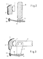
- the outer surface of the bumper assembly is formed by the bumper fascia 3, which extends both transversely and downwardly.
- a foam block 4 is arranged between bumper fascia 3 and bumper beam 1, which absorbs the impact energy when a pedestrian hit the bumper in case of a collision.
- the bumper fascia 3 forms downwardly a lower edge 5, which catches the lower leg of a pedestrian during a collision with the vehicle. Without further stiffening the lower edge 5 of the fascia would be to weak to catch the leg. Therefore the undertray 6 is connected to the lower edge 5, stiffening it up so that it will withstand the impact of the leg and will catch the lower leg properly.
- the undertray 6 is attached at its rearward end to the cooling support 7 of the cooling pack 8. As the cooling support 7 is connected rigidly with the side rails, a stiff attachment of the undertray 6 is ensured.
- the undertray 6 comprises several swages 9. In this case the swages 9 extends in longitudinally direction, but they could also be arranged in transversally direction. Also the swages could be replaced by patterns of ribs and grooves.
- the undertray is connected to other parts, for example chassis or engine, to achieve an even more stiffening behaviour.
- FIG. 2 A cross sectional side view of the bumper assembly at the centre line is illustrated in Figure 2. While the bumper fascia 3 is supported upwardly by the bumper foam 4 and the bumper beam 1, the lower edge 5 of the fascia 3 is supported by the undertray 6. To gain a stiff connection between fascia 3 and undertray 5, which could be separated for service purposes, several elastic bump stops 10 are arranged in the groove of the lower edge 5. The undertray 6 is supported in the cut-outs of the each bump stops, so longitudinally forces resulting from a lower leg impact could be transferred from the lower edge 5 via the bump stops 10 and the undertray 6 to the cooling pack support 7. It is also shown in this section that the undertray extends rearward behind the cooling pack. This could be required by aerodynamics and/or for noise reduction.
- Figure 3 shows the cross sectional view of the bumper assembly at a side rail 2.
- the cooling pack support 7 is attached to the side rail 2, therefore comprising a stiff support for the undertray 6. Swages 9 in the undertray 6 allows tuning of the stiffening behaviour of the whole system bumper fascia 4, bump stops 10, undertray 6 with swages 9 and cooling support.
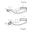
- Figure 4a shows a cross sectional view of the undertray with the line 11 of less bending stiffness, which is mainly oriented parallel to the lower edge 5 of the bumper fascia, dividing the undertray in a forward impact part 12 and a rearward support part 13.
- the support part 13 is fixed to the cooling pack support 7.
- Both the impact part and the support part are stiffened by swatches 14, 15, but the swatches on both parts are divided by the line 11, so that at the line 11 the hinge effect could occur due to the undertray's minor bending stiffness at the line while both parts remain stable itself.
Priority Applications (2)
| Application Number | Priority Date | Filing Date | Title |
|---|---|---|---|
| EP01123401A EP1300293B1 (fr) | 2001-09-28 | 2001-09-28 | Véhicule avec pare-chocs pour la protection des piétons |
| DE60107570T DE60107570T2 (de) | 2001-09-28 | 2001-09-28 | Kraftfahrzeug nit Stossstangenanordnung zum Fussgängerschutz |
Applications Claiming Priority (1)
| Application Number | Priority Date | Filing Date | Title |
|---|---|---|---|
| EP01123401A EP1300293B1 (fr) | 2001-09-28 | 2001-09-28 | Véhicule avec pare-chocs pour la protection des piétons |
Publications (3)
| Publication Number | Publication Date |
|---|---|
| EP1300293A1 true EP1300293A1 (fr) | 2003-04-09 |
| EP1300293A9 EP1300293A9 (fr) | 2003-06-25 |
| EP1300293B1 EP1300293B1 (fr) | 2004-12-01 |
Family
ID=8178779
Family Applications (1)
| Application Number | Title | Priority Date | Filing Date |
|---|---|---|---|
| EP01123401A Expired - Lifetime EP1300293B1 (fr) | 2001-09-28 | 2001-09-28 | Véhicule avec pare-chocs pour la protection des piétons |
Country Status (2)
| Country | Link |
|---|---|
| EP (1) | EP1300293B1 (fr) |
| DE (1) | DE60107570T2 (fr) |
Cited By (25)
| Publication number | Priority date | Publication date | Assignee | Title |
|---|---|---|---|---|
| EP1564088A1 (fr) * | 2004-02-10 | 2005-08-17 | Daimler Chrysler AG | Revêtement pour compartiment moteur d'un véhicule avec protection des pietons contre les chocs |
| WO2006008137A1 (fr) * | 2004-07-21 | 2006-01-26 | Gm Global Technology Operations, Inc. | Element de renfort pour une zone inferieure d'un pare-chocs avant et pare-chocs avant de vehicule automobile equipe d'un tel element |
| EP1561651A3 (fr) * | 2004-02-04 | 2006-04-26 | Bayerische Motoren Werke Aktiengesellschaft | Structure avant de caisse de véhicule automobile |
| WO2006114545A1 (fr) * | 2005-04-27 | 2006-11-02 | Renault S.A.S | Agencement pour le montage d'un bouclier de vehicule automobile |
| DE102005016456A1 (de) * | 2005-04-11 | 2006-11-30 | GM Global Technology Operations, Inc., Detroit | Verstärkungselement für einen unteren Bereich eines Frontstoßfängers mit einem Kühler-Anschubblock, damit ausgerüsteter Frontstoßfänger sowie entsprechend ausgerüstetes Kraftfahrzeug |
| DE102005030419A1 (de) * | 2005-06-30 | 2007-01-04 | Daimlerchrysler Ag | Kraftfahrzeug mit einer Unterschutzeinrichtung |
| EP1754650A1 (fr) | 2005-08-20 | 2007-02-21 | HBPO GmbH | Face avant technique avec support d'assemblage avec poutre basse |
| FR2895341A1 (fr) * | 2005-12-23 | 2007-06-29 | Plastic Omnium Cie | Systeme d'absorption d'energie pour un vehicule automobile |
| EP1777125A3 (fr) * | 2005-10-19 | 2007-07-04 | Kojima Press Industry Co., Ltd. | Système de protection pour piéton et procédé de réglage de la charge du celui-ci |
| EP1842731A1 (fr) * | 2006-04-05 | 2007-10-10 | Ford Global Technologies, LLC. | Système de pare-chocs |
| US7434872B2 (en) | 2004-07-21 | 2008-10-14 | Gm Global Technology Operations, Inc. | Reinforcement element for a lower region of a front bumper and front bumper for a motor vehicle provided with the same |
| US8042847B2 (en) | 2007-12-19 | 2011-10-25 | Sabic Innovative Plastics Ip B.V. | Tray energy absorber and bumper system |
| US8449021B2 (en) | 2010-12-17 | 2013-05-28 | Sabic Innovative Plastics Ip B.V. | Vehicle lower-leg protection device and method of making and using the same |
| US9233662B2 (en) | 2013-08-21 | 2016-01-12 | Mazda Motor Corporation | Vehicle-body front structure of vehicle |
| US9376074B2 (en) | 2014-04-25 | 2016-06-28 | GM Global Technology Operations LLC | Architected automotive impact beam |
| US9469264B2 (en) | 2013-01-18 | 2016-10-18 | Sabic Global Technologies B.V. | Polymer, energy absorber rail extension, methods of making and vehicles using the same |
| US9475434B2 (en) | 2014-08-07 | 2016-10-25 | GM Global Technology Operations LLC | Designs and processes for using discrete stiffeners to create light, stiff and strong automotive structures |
| US9511540B2 (en) | 2014-08-07 | 2016-12-06 | GM Global Technology Operations LLC | Process for securing a micro-truss structure to a panel |
| US9561620B2 (en) | 2014-08-07 | 2017-02-07 | GM Global Technology Operations LLC | Process for securing discrete stiffeners to a panel |
| US9598111B2 (en) | 2014-08-29 | 2017-03-21 | GM Global Technology Operations LLC | Microtruss replacing structural foam in body structural application |
| US9751287B2 (en) | 2014-04-17 | 2017-09-05 | GM Global Technology Operations LLC | Low energy process for making curved sandwich structures with little or no residual stress |
| US9771109B2 (en) | 2013-01-18 | 2017-09-26 | Sabic Global Technologies B.V. | Reinforced body in white and reinforcement therefor |
| US9884436B2 (en) | 2014-04-17 | 2018-02-06 | GM Global Technology Operations LLC | Method for making a curved sandwich structure using a reconfigurable UV source mounting element |
| US10105941B2 (en) | 2014-04-25 | 2018-10-23 | GM Global Technology Operations LLC | Stiffening and/or strengthening a structural member using a pre-made microtruss insert |
| US10144386B2 (en) * | 2015-02-13 | 2018-12-04 | Ford Global Technologies, Llc | Belly pan and energy absorption system for a motor vehicle |
Families Citing this family (11)
| Publication number | Priority date | Publication date | Assignee | Title |
|---|---|---|---|---|
| JP4233042B2 (ja) * | 2004-08-05 | 2009-03-04 | 本田技研工業株式会社 | 車両用バンパー構造 |
| DE102007019481B4 (de) * | 2007-04-25 | 2017-10-19 | Volkswagen Ag | Frontendmodul für ein Fahrzeug, insbesondere für ein Kraftfahrzeug |
| US8322780B2 (en) | 2010-12-20 | 2012-12-04 | Sabic Innovative Plastics Ip B.V. | Reinforced body in white and method of making and using the same |
| DE102010056390A1 (de) * | 2010-12-28 | 2012-06-28 | GM Global Technology Operations LLC | Frontbereich eines Fahrzeugs und Fahrzeug |
| DE102013002307A1 (de) | 2013-02-06 | 2014-08-07 | GM Global Technology Operations LLC (n. d. Ges. d. Staates Delaware) | Frontpartie für ein Kraftfahrzeug |
| JP6131837B2 (ja) | 2013-11-15 | 2017-05-24 | マツダ株式会社 | 車両の前部構造 |
| DE102014100795B4 (de) | 2013-11-19 | 2022-09-01 | Dr. Ing. H.C. F. Porsche Aktiengesellschaft | Frontendmodul für ein Kraftfahrzeug |
| EP3513958A3 (fr) | 2014-06-16 | 2019-10-23 | SABIC Global Technologies B.V. | Procédé de fabrication d'un stratifié et outil de moulage |
| WO2017109647A1 (fr) | 2015-12-23 | 2017-06-29 | Sabic Global Technologies B.V. | Élément inférieur d'absorption d'énergie composite/hybride pour automobiles, et son procédé de fabrication |
| USD820749S1 (en) | 2015-12-29 | 2018-06-19 | Sabic Global Technologies B.V. | Roof component for a motor vehicle |
| DE102016008210A1 (de) * | 2016-07-06 | 2017-08-31 | Daimler Ag | Deformationseinrichtung für einen Vorbau eines Kraftwagens |
Citations (8)
| Publication number | Priority date | Publication date | Assignee | Title |
|---|---|---|---|---|
| DE3003568A1 (de) | 1980-02-01 | 1981-08-06 | Daimler-Benz Ag, 7000 Stuttgart | Stossschutzvorrichtung fuer fahrzeuge, insbesondere kraftfahrzeuge |
| JPH1178743A (ja) | 1997-09-03 | 1999-03-23 | Kansei Corp | 車両用エアバッグ |
| EP0983909A1 (fr) | 1998-09-02 | 2000-03-08 | Ford Global Technologies, Inc. | Assemblage de renforcement pour système de pare-chocs de véhicules automobiles |
| EP1000840A2 (fr) * | 1998-11-09 | 2000-05-17 | Volkswagen Aktiengesellschaft | Structure de suppport de la partie avant pour un véhicule automobile |
| WO2000058144A1 (fr) * | 1999-03-29 | 2000-10-05 | Peguform France | Combinaison d'une peau de pare-chocs et d'un carenage sous moteur pour vehicule |
| EP1072476A2 (fr) * | 1999-07-26 | 2001-01-31 | Dynamit Nobel Kunststoff GmbH | Support de pare-chocs pour une meilleure protection des piétons sur les véhicules automobiles |
| GB2355435A (en) * | 1999-10-18 | 2001-04-25 | Ford Global Tech Inc | A vehicle bumper arrangement |
| EP1103428A2 (fr) * | 1999-11-24 | 2001-05-30 | Benteler Ag | Ensemble pare-chocs |
-
2001
- 2001-09-28 EP EP01123401A patent/EP1300293B1/fr not_active Expired - Lifetime
- 2001-09-28 DE DE60107570T patent/DE60107570T2/de not_active Expired - Lifetime
Patent Citations (8)
| Publication number | Priority date | Publication date | Assignee | Title |
|---|---|---|---|---|
| DE3003568A1 (de) | 1980-02-01 | 1981-08-06 | Daimler-Benz Ag, 7000 Stuttgart | Stossschutzvorrichtung fuer fahrzeuge, insbesondere kraftfahrzeuge |
| JPH1178743A (ja) | 1997-09-03 | 1999-03-23 | Kansei Corp | 車両用エアバッグ |
| EP0983909A1 (fr) | 1998-09-02 | 2000-03-08 | Ford Global Technologies, Inc. | Assemblage de renforcement pour système de pare-chocs de véhicules automobiles |
| EP1000840A2 (fr) * | 1998-11-09 | 2000-05-17 | Volkswagen Aktiengesellschaft | Structure de suppport de la partie avant pour un véhicule automobile |
| WO2000058144A1 (fr) * | 1999-03-29 | 2000-10-05 | Peguform France | Combinaison d'une peau de pare-chocs et d'un carenage sous moteur pour vehicule |
| EP1072476A2 (fr) * | 1999-07-26 | 2001-01-31 | Dynamit Nobel Kunststoff GmbH | Support de pare-chocs pour une meilleure protection des piétons sur les véhicules automobiles |
| GB2355435A (en) * | 1999-10-18 | 2001-04-25 | Ford Global Tech Inc | A vehicle bumper arrangement |
| EP1103428A2 (fr) * | 1999-11-24 | 2001-05-30 | Benteler Ag | Ensemble pare-chocs |
Cited By (35)
| Publication number | Priority date | Publication date | Assignee | Title |
|---|---|---|---|---|
| EP1561651A3 (fr) * | 2004-02-04 | 2006-04-26 | Bayerische Motoren Werke Aktiengesellschaft | Structure avant de caisse de véhicule automobile |
| EP1564088A1 (fr) * | 2004-02-10 | 2005-08-17 | Daimler Chrysler AG | Revêtement pour compartiment moteur d'un véhicule avec protection des pietons contre les chocs |
| US8132851B2 (en) | 2004-07-21 | 2012-03-13 | GM Global Technology Operations LLC | Reinforcing element for a lower area of a front bumper, and correspondingly equipped bumper for a motor vehicle |
| DE102004035435A1 (de) * | 2004-07-21 | 2006-03-16 | GM Global Technology Operations, Inc., Detroit | Verstärkungselement für einen unteren Bereich eines Frontstoßfängers, sowie damit augerüsteter Frontstoßfänger für ein Kraftfahrzeug |
| US7434872B2 (en) | 2004-07-21 | 2008-10-14 | Gm Global Technology Operations, Inc. | Reinforcement element for a lower region of a front bumper and front bumper for a motor vehicle provided with the same |
| WO2006008137A1 (fr) * | 2004-07-21 | 2006-01-26 | Gm Global Technology Operations, Inc. | Element de renfort pour une zone inferieure d'un pare-chocs avant et pare-chocs avant de vehicule automobile equipe d'un tel element |
| DE102005016456A1 (de) * | 2005-04-11 | 2006-11-30 | GM Global Technology Operations, Inc., Detroit | Verstärkungselement für einen unteren Bereich eines Frontstoßfängers mit einem Kühler-Anschubblock, damit ausgerüsteter Frontstoßfänger sowie entsprechend ausgerüstetes Kraftfahrzeug |
| WO2006114545A1 (fr) * | 2005-04-27 | 2006-11-02 | Renault S.A.S | Agencement pour le montage d'un bouclier de vehicule automobile |
| FR2885110A1 (fr) * | 2005-04-27 | 2006-11-03 | Renault Sas | Agencement pour le montage d'un bouclier de vehicule automobile |
| JP4859918B2 (ja) * | 2005-04-27 | 2012-01-25 | ルノー・エス・アー・エス | 自動車面材の取付け方法 |
| JP2008539123A (ja) * | 2005-04-27 | 2008-11-13 | ルノー・エス・アー・エス | 自動車面材の取付け方法 |
| DE102005030419A1 (de) * | 2005-06-30 | 2007-01-04 | Daimlerchrysler Ag | Kraftfahrzeug mit einer Unterschutzeinrichtung |
| EP1754650A1 (fr) | 2005-08-20 | 2007-02-21 | HBPO GmbH | Face avant technique avec support d'assemblage avec poutre basse |
| US7597383B2 (en) | 2005-10-19 | 2009-10-06 | Kojima Press Industry Co., Ltd. | Pedestrian protection apparatus, and method of tuning load characteristic of the apparatus |
| EP1777125A3 (fr) * | 2005-10-19 | 2007-07-04 | Kojima Press Industry Co., Ltd. | Système de protection pour piéton et procédé de réglage de la charge du celui-ci |
| CN100410111C (zh) * | 2005-10-19 | 2008-08-13 | 小岛压力加工工业株式会社 | 行人保护装置以及调整该装置的负载特性的方法 |
| US7681700B2 (en) | 2005-12-23 | 2010-03-23 | Compagnie Plastic Omnium | Energy absorber system for a motor vehicle |
| CN101351358B (zh) * | 2005-12-23 | 2011-09-21 | 全耐塑料公司 | 用于机动车辆的能量吸收系统 |
| WO2007074300A3 (fr) * | 2005-12-23 | 2007-08-23 | Plastic Omnium Cie | Systeme d'absorption d'energie pour un vehicule automobile |
| FR2895341A1 (fr) * | 2005-12-23 | 2007-06-29 | Plastic Omnium Cie | Systeme d'absorption d'energie pour un vehicule automobile |
| EP1842731A1 (fr) * | 2006-04-05 | 2007-10-10 | Ford Global Technologies, LLC. | Système de pare-chocs |
| US8042847B2 (en) | 2007-12-19 | 2011-10-25 | Sabic Innovative Plastics Ip B.V. | Tray energy absorber and bumper system |
| US8449021B2 (en) | 2010-12-17 | 2013-05-28 | Sabic Innovative Plastics Ip B.V. | Vehicle lower-leg protection device and method of making and using the same |
| US9469264B2 (en) | 2013-01-18 | 2016-10-18 | Sabic Global Technologies B.V. | Polymer, energy absorber rail extension, methods of making and vehicles using the same |
| US9771109B2 (en) | 2013-01-18 | 2017-09-26 | Sabic Global Technologies B.V. | Reinforced body in white and reinforcement therefor |
| US9233662B2 (en) | 2013-08-21 | 2016-01-12 | Mazda Motor Corporation | Vehicle-body front structure of vehicle |
| US9751287B2 (en) | 2014-04-17 | 2017-09-05 | GM Global Technology Operations LLC | Low energy process for making curved sandwich structures with little or no residual stress |
| US9884436B2 (en) | 2014-04-17 | 2018-02-06 | GM Global Technology Operations LLC | Method for making a curved sandwich structure using a reconfigurable UV source mounting element |
| US9376074B2 (en) | 2014-04-25 | 2016-06-28 | GM Global Technology Operations LLC | Architected automotive impact beam |
| US10105941B2 (en) | 2014-04-25 | 2018-10-23 | GM Global Technology Operations LLC | Stiffening and/or strengthening a structural member using a pre-made microtruss insert |
| US9561620B2 (en) | 2014-08-07 | 2017-02-07 | GM Global Technology Operations LLC | Process for securing discrete stiffeners to a panel |
| US9511540B2 (en) | 2014-08-07 | 2016-12-06 | GM Global Technology Operations LLC | Process for securing a micro-truss structure to a panel |
| US9475434B2 (en) | 2014-08-07 | 2016-10-25 | GM Global Technology Operations LLC | Designs and processes for using discrete stiffeners to create light, stiff and strong automotive structures |
| US9598111B2 (en) | 2014-08-29 | 2017-03-21 | GM Global Technology Operations LLC | Microtruss replacing structural foam in body structural application |
| US10144386B2 (en) * | 2015-02-13 | 2018-12-04 | Ford Global Technologies, Llc | Belly pan and energy absorption system for a motor vehicle |
Also Published As
| Publication number | Publication date |
|---|---|
| DE60107570T2 (de) | 2005-12-15 |
| DE60107570D1 (de) | 2005-01-05 |
| EP1300293B1 (fr) | 2004-12-01 |
| EP1300293A9 (fr) | 2003-06-25 |
Similar Documents
| Publication | Publication Date | Title |
|---|---|---|
| EP1300293B1 (fr) | Véhicule avec pare-chocs pour la protection des piétons | |
| EP1118530B1 (fr) | Structure de la partie avant pour un véhicule | |
| US7735902B2 (en) | Front structure of a motor vehicle | |
| EP1215093B1 (fr) | Système de pare-chocs pour véhicule | |
| US6485072B1 (en) | Bumper system for motor vehicles | |
| US6193274B1 (en) | Vehicle subframes | |
| US7210719B2 (en) | Vehicle bumper beam mounting structure | |
| US6513843B1 (en) | Pedestrian protection leg spoiler | |
| US7828374B2 (en) | Structure of the front part of a motor vehicle | |
| US6056337A (en) | Impact energy absorption structure for motor vehicle | |
| US6755459B2 (en) | Pedestrian protection assembly | |
| US9254801B2 (en) | Front vehicle-body structure of vehicle | |
| JP2005534555A (ja) | 歩行者の負傷を軽減するバンパー | |
| KR100974748B1 (ko) | 자동차의 범퍼 백빔 구조 | |
| JP4617681B2 (ja) | 自動車の前部車体構造 | |
| US20030042759A1 (en) | Structural member for a vehicle frame assembly | |
| CN108001210B (zh) | 用于行人安全的可塌缩散热器支撑件支架 | |
| JP2005297726A (ja) | 自動車用バンパ | |
| US20090085372A1 (en) | Arrangement for vehicle cabs | |
| JP4479637B2 (ja) | 車両用バンパ構造 | |
| JP6056738B2 (ja) | 車両の前部構造 | |
| US8141917B2 (en) | Energy absorption impact system for motor vehicles | |
| JP2004532770A (ja) | フレキシブルに取り付けられたボンネットを備える自動車ボディ | |
| EP1992525B1 (fr) | Le support - parenthese pour le systeme de protection frontal | |
| US20080284207A1 (en) | Frame Structure for Receiving a Pivotally Mounted Truck Driver's Cab |
Legal Events
| Date | Code | Title | Description |
|---|---|---|---|
| PUAI | Public reference made under article 153(3) epc to a published international application that has entered the european phase |
Free format text: ORIGINAL CODE: 0009012 |
|
| 17P | Request for examination filed |
Effective date: 20020903 |
|
| AK | Designated contracting states |
Kind code of ref document: A1 Designated state(s): AT BE CH CY DE DK ES FI FR GB GR IE IT LI LU MC NL PT SE TR |
|
| AX | Request for extension of the european patent |
Extension state: AL LT LV MK RO SI |
|
| RTI1 | Title (correction) |
Free format text: BUMPER ASSEMBLY OF A MOTOR VEHICLE FOR PEDESTRIAN PROTECTION |
|
| 17Q | First examination report despatched |
Effective date: 20030819 |
|
| AKX | Designation fees paid |
Designated state(s): DE FR GB |
|
| GRAP | Despatch of communication of intention to grant a patent |
Free format text: ORIGINAL CODE: EPIDOSNIGR1 |
|
| RAP1 | Party data changed (applicant data changed or rights of an application transferred) |
Owner name: FORD GLOBAL TECHNOLOGIES, LLC |
|
| RIC1 | Information provided on ipc code assigned before grant |
Ipc: 7B 60R 19/56 B Ipc: 7B 60R 19/12 A Ipc: 7B 60R 21/34 B |
|
| RTI1 | Title (correction) |
Free format text: MOTOR VEHICLE WITH BUMPER ASSEMBLY FOR PEDESTRIAN PROTECTION |
|
| GRAS | Grant fee paid |
Free format text: ORIGINAL CODE: EPIDOSNIGR3 |
|
| GRAA | (expected) grant |
Free format text: ORIGINAL CODE: 0009210 |
|
| AK | Designated contracting states |
Kind code of ref document: B1 Designated state(s): DE FR GB |
|
| REG | Reference to a national code |
Ref country code: GB Ref legal event code: FG4D Free format text: NOT ENGLISH |
|
| REG | Reference to a national code |
Ref country code: GB Ref legal event code: ERR Free format text: THE ABOVE EP(UK) PATENT WAS ADVERTISED IN THE PATENTS AND DESIGNS JOURNAL NO. 6028 DATED 20041201 AS GERMAN. NOTIFICATION RECEIVED FROM THE EUROPEAN PATENT OFFICE THAT THE PUBLICATION LANGUAGE IS ACTUALLY ENGLISH. |
|
| REF | Corresponds to: |
Ref document number: 60107570 Country of ref document: DE Date of ref document: 20050105 Kind code of ref document: P |
|
| PLBE | No opposition filed within time limit |
Free format text: ORIGINAL CODE: 0009261 |
|
| STAA | Information on the status of an ep patent application or granted ep patent |
Free format text: STATUS: NO OPPOSITION FILED WITHIN TIME LIMIT |
|
| 26N | No opposition filed |
Effective date: 20050902 |
|
| ET | Fr: translation filed | ||
| PGFP | Annual fee paid to national office [announced via postgrant information from national office to epo] |
Ref country code: DE Payment date: 20100930 Year of fee payment: 10 |
|
| PGFP | Annual fee paid to national office [announced via postgrant information from national office to epo] |
Ref country code: GB Payment date: 20110826 Year of fee payment: 11 Ref country code: FR Payment date: 20110901 Year of fee payment: 11 |
|
| GBPC | Gb: european patent ceased through non-payment of renewal fee |
Effective date: 20120928 |
|
| REG | Reference to a national code |
Ref country code: FR Ref legal event code: ST Effective date: 20130531 |
|
| PG25 | Lapsed in a contracting state [announced via postgrant information from national office to epo] |
Ref country code: GB Free format text: LAPSE BECAUSE OF NON-PAYMENT OF DUE FEES Effective date: 20120928 Ref country code: DE Free format text: LAPSE BECAUSE OF NON-PAYMENT OF DUE FEES Effective date: 20130403 |
|
| REG | Reference to a national code |
Ref country code: DE Ref legal event code: R119 Ref document number: 60107570 Country of ref document: DE Effective date: 20130403 |
|
| PG25 | Lapsed in a contracting state [announced via postgrant information from national office to epo] |
Ref country code: FR Free format text: LAPSE BECAUSE OF NON-PAYMENT OF DUE FEES Effective date: 20121001 |