EP1300285A1 - Anordnung zur Halterung unterschiedlicher Container-Typen auf einem Fahrgestell - Google Patents
Anordnung zur Halterung unterschiedlicher Container-Typen auf einem Fahrgestell Download PDFInfo
- Publication number
- EP1300285A1 EP1300285A1 EP02021520A EP02021520A EP1300285A1 EP 1300285 A1 EP1300285 A1 EP 1300285A1 EP 02021520 A EP02021520 A EP 02021520A EP 02021520 A EP02021520 A EP 02021520A EP 1300285 A1 EP1300285 A1 EP 1300285A1
- Authority
- EP
- European Patent Office
- Prior art keywords
- locking device
- arrangement according
- locking
- chassis
- container
- Prior art date
- Legal status (The legal status is an assumption and is not a legal conclusion. Google has not performed a legal analysis and makes no representation as to the accuracy of the status listed.)
- Granted
Links
Images


Classifications
-
- B—PERFORMING OPERATIONS; TRANSPORTING
- B60—VEHICLES IN GENERAL
- B60P—VEHICLES ADAPTED FOR LOAD TRANSPORTATION OR TO TRANSPORT, TO CARRY, OR TO COMPRISE SPECIAL LOADS OR OBJECTS
- B60P7/00—Securing or covering of load on vehicles
- B60P7/06—Securing of load
- B60P7/13—Securing freight containers or forwarding containers on vehicles
- B60P7/132—Securing freight containers or forwarding containers on vehicles twist-locks for containers or frames
-
- B—PERFORMING OPERATIONS; TRANSPORTING
- B60—VEHICLES IN GENERAL
- B60P—VEHICLES ADAPTED FOR LOAD TRANSPORTATION OR TO TRANSPORT, TO CARRY, OR TO COMPRISE SPECIAL LOADS OR OBJECTS
- B60P1/00—Vehicles predominantly for transporting loads and modified to facilitate loading, consolidating the load, or unloading
- B60P1/64—Vehicles predominantly for transporting loads and modified to facilitate loading, consolidating the load, or unloading the load supporting or containing element being readily removable
- B60P1/6418—Vehicles predominantly for transporting loads and modified to facilitate loading, consolidating the load, or unloading the load supporting or containing element being readily removable the load-transporting element being a container or similar
- B60P1/6481—Specially adapted for carrying different numbers of container or containers of different sizes
Definitions
- the invention relates to an arrangement for holding different types of containers on a chassis.
- Containers of various sizes are available as swap bodies on chassis commonly used, which fittings in the lower area of the front and long sides have in which interlocks on the vehicle side can engage.
- so-called High Cube (HC) - or Gooseneck containers matter which towards the front in an area around the central longitudinal plane of the container have a so-called Gooseneck tunnel, which is a step of Sides of the chassis side member are gripped laterally.
- HC High Cube
- Gooseneck tunnel which is a step of Sides of the chassis side member are gripped laterally.
- Containers 20 'and 40' long with and without are particularly common Gooseneck tunnel as well as containers of length 45 'with Gooseneck tunnel, whereby for the latter to comply with regulations regarding total length and front swing radius is known to chamfer the corner pillars to a limited swivel radius so as not to exceed the kingpin.
- HC containers 45 are the openings in the bevelled corner fittings to accommodate horizontal locking pins opposite the position for containers of the same width without bevelling to the central longitudinal plane of the Containers offset by a small amount.
- Containers with such a bevel Corner fittings are described, for example, in WO98 / 19883 A1.
- a device which on a Crossbeams can be swiveled away to the center of the container contains.
- the swivel arms have a vertical at the outer ends Trunnion lock and secondly a horizontal locking pin lock for HC containers with rectangular fittings and can be in unfolded position to hold suitable containers. additionally are close to the central longitudinal plane of the chassis on the cross member further locking pin locks are provided, which within a permissible turning radius around the kingpin and in accordingly Fittings located near the central longitudinal plane of a 45 'HC container can intervene which must be provided for this separately.
- the swivel arms are also completely in the park position within the specified turning radius.
- Locking arrangements with a pivot lock and a pin lock are also from DE 196 06 263 A1, where a pivot lock housing around a vertical one leading through the plug pin Swivel axis can be pivoted and placed on the cross member, and from DE 100 47 093 A1, where the pivot axis in the direction of travel before Plug pin is known.
- These locking arrangements in which the Trunnion locking housing in its holding position in the locking direction of the plug pin, but are not also for holding 45 'HC containers suitable.
- the invention has for its object an advantageous arrangement for Specify bracket of different containers.
- the arrangement separate from the plug pin of the second locking device the first locking device with the locking pin for Container of a first container type on a swivel arm advantageously allows the simple relocation of the first locking device between a stop position in which a container by means of the vertical of the pivot engaging below in the corner fitting, and one Parking position in which when a 45 'HC container is locked by means of the Pin of the second locking device, the first locking device completely within the prescribed turning radius King's cone lies.
- the second locking device preferably has a bolt carrier on which the plug pin is arranged and which from a holding position, in which a container of the second type can be locked in position is displaceable relative to the cross member.
- the bolt carrier is also pivotable relative to the cross member, different from the swivel arm of the first locking arrangement Swivel arm designed.
- socket pins and locking pins as locking elements for different container types over different pivotable support arms on a common, in the longitudinal direction of the chassis variably positionable crossbeam enables independent mechanical positioning of one of the locking elements in its respective stop position on the corner fitting of the associated container type and on the other hand the pivoting of the other locking element from its holding position, insofar as this is necessary for the use of the one locking element is annoying.
- a common cross member leads to a particularly advantageous one and compact arrangement without, as in the case of DE 200 12 977 U1 additional fittings near the central longitudinal axis are required.
- the second locking device is especially for long HC container types provided with bevelled corner fittings, in which the position of the plug pin in relation to non-bevelled corner fittings is offset by approx. 85 mm to the chassis longitudinal center plane.
- a third locking device can be used for this be present, which is structurally combined with the first Locking device can be arranged on the swivel arm. In others Execution can also be the same due to the transverse displaceability of the bolt carrier Plug pins used for the second and third locking device his.
- a stop position of the various locking devices understood the positions in which the respective locking elements, in particular plug pins or vertical locking pins in engagement with Container fittings are available. Since only one of the locks is used at a time the other interlocks will be located insofar as they are currently used Interlocking could stand in the way or otherwise interfere, then preferably in defined positions designated as parking positions, which are different from the stopping positions.
- the locking devices are advantageously in their holding positions and preferably also in theirs Parking positions can be determined by securing elements. Relocation of a locking device between the stop position and the parking position Depending on the embodiment, movement components with evasive function in Include intermediate positions.
- the third locking device can be in various advantageous designs with the combination of the first and the second according to the invention Locking device can be realized.
- a first execution can be the third Locking device on its own, relative to the bolt carrier second locking device and / or to the swivel arm of the first locking device provide.
- Another advantageous embodiment can provide that the third locking device the same socket pin used as the second locking device, for which a carrier arrangement for this plug pin in the direction of the cross member, i.e. transverse to the longitudinal axis of the chassis adjustable and with the plug pin in different distances Central longitudinal plane can be brought. For example, this can be similar to that known displacement of a wing lock one pivotable bolt arm carrying telescopic support tube.
- a another variant can provide that in the case of a about a vertical pivot axis, the pivot axis in a slot and thereby the lateral distance of the carrier and so that the pivot pin can be varied.
- the third locking device at the end of the swivel arm carrying the first locking device be arranged together with this.
- this is shown in the illustrations and together with these explained in detail.
- the first locking device can be pivoted into the parking position with the lever arm in an area within the permissible spin circle to be brought around the kingpin.
- the pivoting of the Swivel arms can be made around a substantially horizontal axis is preferably closer to the median longitudinal plane than a mechanism for horizontal displacement of the plug pin of the second locking device.
- the swivel arm can then advantageously in the form of a second locking device downwardly open U-profile be in the holding position of the third locking device surrounds the second locking device laterally in its parking position.
- the pivot arm is preferably pivotable about a vertical axis in particular in a constructively advantageous manner with a pivot axis of a fixed bolt carrier connected to the plug pin of the second locking device can coincide.
- the swivel arm is out of the holding position by almost 180 °, preferably between 150 ° and 180 ° in the parking position pivotable.
- the pivot axis of the pivot arm of the first locking device is advantageously in the direction transverse to the longitudinal direction of the chassis between the holding position of the socket pins of the second locking device and the central longitudinal plane of the chassis.
- the first locking device is advantageously less than in its parking position 50% of half a container width spaced from the central longitudinal plane.
- the cross member is advantageously at least partially in the direction of travel open profile and takes the swivel arm and possibly also the connected to this first locking device through the profile opening at least in part.
- first and bolt carrier of the second locking device advantageously take Swivel arm and bolt carrier in relation to the swivel axis axial, i.e. vertical sections and can so simply pivoted against each other about the common pivot axis become. It may be advantageous if bolt carriers and Swivel arm are also radially displaceable relative to one another, on the one hand the small difference in the lateral distance from the median longitudinal plane of the Chassis between the locking elements of the second and third To be able to implement locking elements in a constructively advantageous manner and on the other hand the bolt carriers on the first locking device on the To guide the swivel arm past.
- the second locking device can in another advantageous embodiment be designed as a non-pivoting bolt carrier, but which, for. B. by moving transversely to the longitudinal direction of the chassis relative to Cross member displaceable and / or removable from the cross member and, if necessary in a different position, in particular a parking position in this again used.
- the socket pin of the second Locking device arranged in a fixed position with respect to the cross member his.
- the crossbeam, together with the locking devices, can advantageously be plug-in bolts also with containers lying on the chassis in Vehicle longitudinal direction can be moved and locked in the holding position.
- the cross member is laterally opposite to the two Positions of the plug pins of the second locking device in one piece continuous and therefore particularly stable.
- additional elements such. B. as welded support plates for vertical support of position variables relative to the cross member Locking devices may be provided.
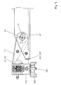
- FIGS. 1 and 2 show three different ones Locking devices together in their respective holding positions. Not all elements are drawn in for clarity to improve the illustrations.
- the first locking arrangement is arranged at the end of a cross member QT, which at least in the area of the locking arrangement as a U-shaped Profile with surfaces QT-O, QT-R and QT-U executed and in the direction of travel LR, i.e. against the wall QT-R at least partially, preferably is predominantly or completely open.
- a locking housing VG1 contains the first locking element Locking device a pivot VK, which is vertical over the upper Surface of the locking housing VG1 protrudes and into a lower opening of a corner fitting EB1 of a container protrudes. By twisting the Pin is about a vertical axis by means of the locking lever VH Fitting locked with the locking housing. Trunnion latches are well known and common, so on details the pivot lock is not discussed here.
- the housing is also a third locking device with a Socket bolt SB1 housed.
- the socket pin protrudes horizontally against the Direction of travel beyond the locking housing VG1 and can be in a Intervene at the front opening of a non-bevelled corner fitting.
- the locking housing VG1 is held on a swivel arm, which is constructed from two parallel horizontal arm plates A1, A2, which with the locking housing are preferably welded.
- the swivel arm is horizontal about a vertical swivel axis SA in the direction of arrow AS Outlined stop position of the first and third locking device pivotable.
- the arm plates A1, A2 run within the profile of the cross member QT parallel to its horizontal walls QT-O, QT-U and are in contact these at or opposite them with a small distance.
- a second horizontal socket pin SB2 as a locking element second locking device is fixed with a plate-shaped carrier T2 connected.
- the beam T2 has one of the rear walls QT-R of the cross beam profile opposite edge, which runs obliquely against the rear wall QT-R and in the sketched holding position of the second locking device inside of a permissible rotating arc around the king pin of the chassis support runs and clings closely to the arc.
- the second socket pin SB2 protrudes horizontally through the rear wall QT-R of the cross member formed stop edge for a container front edge and can engage in a beveled corner of a 45'-HC container.
- Such a relative pivoting is in the advantageous sketched embodiment enables the carrier T2 a Has elongated hole LL about the pivot shaft SW of the pivot axis SA and by guiding the elongated hole on the swivel shaft from the locking housing radially shifted away and in the shifted position in the direction of arrow TS can be pivoted.
- the shaft SW is flattened on two sides.
- a Relative radial displacement of the swivel arm A1, A2 allows outwards likewise the relative pivoting.
- the carrier plate T2 lies axially with respect to the vertical pivot axis SA Direction spaced between and parallel to the arm plates A1, A2.
- To stabilize the various locking devices against vertical forces are horizontal support plates SP1, SP2 with the rear wall QT-R of the cross member welded, which in the axial direction between them Beam 2 and against the horizontal walls QT-O, QT-U of the cross beam Close arm plates A2 or A1 tightly.
- the spacers also as stepped washers be formed and larger than the shaft diameter Bores of the arm plates A1, A2 can lie.
- the plug pins SB1, SB2 are in Fig. 1 and Fig. 2 as in the sketched holding position drawn in parallel to the longitudinal direction LR of the chassis.
- the plug pins can also be approximately tangential about the pivot axis be designed to when pivoting into the openings of the corner fittings to have as little lateral play in the openings as possible.
- the locking housing VG1 While using the second locking device with the in a bevelled corner fitting engaging socket bolt SB2 the locking housing VG1 must be pivoted far to within the allowable Lying circle DR can lie when using the third locking device the pivoting away of the second locking device be limited to a small swivel angle sufficient to the second socket pin completely in the direction of travel in front of the through the rear wall QT-R formed stop surface.
- the carrier plate T2 with the second bolt SB2 can then remain between the arm plates A1, A2. This enables the swivel arm to be designed as in the holding position in Direction of travel completed or one-piece U-profile by another plate with less sensitivity to shear deformation due to vertical Force acting on the first or third locking device.
- the second locking device also illustrates the possibilities of the swivel arm on its side lying here in the direction of travel between plates A1, A2 to form a U-shape or the swivel arm e.g. designed as an open U-shape at the bottom and around a horizontal axis away from above or from above via the parking position of the second locking device to pan.
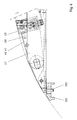
- Fig. 7 shows a section looking in the direction transverse to the longitudinal axis of the vehicle a variant with a horizontally swiveling swivel arm SWH in a U-shape open against the direction of travel
- Fig. 8 a vertically pivotable SWH swivel arm with U-shape open at the bottom.
- FIG. 5 shows a top view of a situation in which the third locking device with the first plug pin SB1 in an opening on the front not bevelled corner fitting EB3 e.g. a 20 'or 40' HC container engages and the support plate T2 by a small swivel angle against the 2 is pivoted position, but unchanged from the arm plates A1, A2 is completely covered.
- the support plate T2 with the plug pin But SB2 can also move completely out of range by a larger angle be swiveled out of the swivel arm.
- the locking devices can be in their respective holding positions advantageously be held by security devices, in particular due to the horizontal swivel movement around the vertical swivel axis SA especially by locking the swiveling movement is advantageous.
- a fuse can be aligned, for example, by a Securing holes SH of cross member and carrier plate T2 or Swivel arm A1, A2 insertable safety pin SI.
- the cross member QT essentially extends laterally with its rear wall QT-R up to the plug pin SB2, so that a high stiffening against Vertical forces are given.
- the crossmember can end in front of the plug pin SB2 or embrace it.
- An additional support for the locking devices is carried out by the provided in the end regions of the cross member Support plates SP1, SP2.
- FIG. 3 and 4 show an advantageous embodiment of a locking housing VG1, which by pivoting the pivot VK in an area between the upper and lower boundary surface of the locking housing, the vertically not over the arm plates A1 and A2 down or protrude above, brought into a particularly flat shape and thus also be pivoted far into the cross member's open profile in the direction of travel can.
- the locking pin which is held in a pin carrier and is rotatably guided about a horizontal tilt axis KA and can be tilted in the upright position outlined in FIG. 3 by a releasable latch RI is supported.
- the latch is by one of the first plug pins SB1 facing away and firmly connected to it and by a vertical Axis BA formed in the locking housing pivotable extension, which is supported on the bottom of the locking housing and in one Recess AU of the pin carrier ZT lies.
- the recess AU secures at the same time the plug pin SB1 against pivoting about the axis BA.
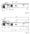
- FIGS. 9 to 11 are largely based on the preferred embodiment already explained with reference to FIGS. 1 to 6.
- the preceding statements in this regard apply in scope of the correspondences essentially also for those below in more detail explained further explanations.
- the construction of the cross member QT as at least partially open in the direction of travel the Construction of a swivel arm from two parallel plates A1, A2 and a locking housing with a lowerable pivot as the first locking device accepted.
- Bolt carrier is plate-shaped and between support plates SP1, SP2 kept stable.
- the first locking device often referred to as a twist lock, vertically in a container corner fitting engaging from below and lockable by rotation Pin understood, whereas as a second and third locking device horizontal plug pins are used.
- FIG. 9 An advantageous embodiment is in different positions in FIG. 9 and views outlined, here the second and third locking device are identical in the form of a plug pin SB2.
- the socket pin is open arranged a bolt carrier BT, which as a slide in a transverse to Longitudinal direction LR of the chassis sliding direction SR displaceable and is removed from the cross member by this displacement and / or in at least two different positions in the sliding direction can be.
- the setting can be done, for example, with a safety bolt SIA take place through openings in the cross member and in the bolt carrier be upheld.
- the bolt carrier BT is in the sketch according to FIG. 9 (A) in a working position to hold an overlong 45'-HC container as a second type of container with bevelled corner fittings.
- the side Distance D1 of the plug pin SB2 from the center plane ME of the chassis is then about 1045 mm.
- the plug pin SB2 is one Distance difference DS further out at a distance D2 from the central longitudinal plane ME of the chassis with D2 approx. 1130 mm and can be used as a third locking device for holding a standard HC container as the third container type serve.
- Locking and unlocking a container of the second or third type the chassis is made by moving the cross member in the direction of the arrow TS parallel to the vehicle's longitudinal direction LR, without swiveling the bolt carrier BT is required.
- Such an approach to locking and Unlocking is also possible with the versions described above and advantageous, with the possible pivotability of the the bolt-carrying arm only for changing the locking device serves.
- the longitudinal displaceability of the front cross member in longitudinal guides is known per se and can advantageously be operated hydraulically his.
- the first locking device with a vertically in a corner fitting Container of the first type engaging pin VK in a locking housing VG is in a parking position by a in Fig. 9 (A) and Fig. 9 (B) second security pin SIP set.
- the cross member at least in sections in the direction of travel, d. H. the cross member rear wall QTR facing away, is above and the locking housing attached to a swivel arm VG the first locking device in the parking position between upper QTO and lower QTU plate of the cross member and within the spin circle DR lies around the kingpin of the chassis support. in this connection can, as described for these previous examples, the locking pin swung out of the upright position into the locking housing his.
- the lever VH By means of the lever VH, the pin VK be rotated around its vertical axis.
- the bolt carrier BT which is shown in isolation between Fig. 9 (B) and Fig. 9 (C) is removed from the cross member and into its in Fig. 9 (C) and Fig. 9 (D) outlined parking position between the upper and lower plate QTO, QTU of the cross member.
- two openings TL1, TL2 through the carrier plate can be clearly seen, which are used to fix the bolt carrier in the two working positions 9 (A) and 9 (B).
- a recess TF encompasses in the working position 9 (A) and the parking position of FIG. 9 (C) the pivot axis SA.
- the opening of the recess facing away from the bolt can be used for Protection against unintentional failure bridged or completed his.
- the lateral displaceability of the bolt carrier from the position according to FIG. 9 (A) with completely within a spin circle DR with a radius of 2040 mm around the king of the chassis support on a towing vehicle lying locking arrangement leads through the lateral displacement of the Bolt carrier in the position shown in Fig. 9 (B) to only a small protrusion the bolt carrier over its position according to Fig. 9 (A).
- the resulting overhang of the container at the rear of the vehicle 60 mm is usually tolerable.
- the swivel arm, on which the locking housing VG is attached to the outside can be made of two vertically spaced arm plates A1, A2 exist, but also additional vertical Wall sections between arm plates A1, A2 included for stiffening.
- Breakthroughs ALA, ALP in the plates A1, A2 serve to define the Swivel arms in the working position according to Fig. 9 (C), (D) or the parking position 9 (A), (B).
- Fig. 10 a modification is shown in which one corresponding to Fig. 9 (C) Working position of the first locking device with the vertical Do not peg the movable bolt carrier with the SB plug bolt pulled out of the cross member, but in the position shown in Fig. 9 (A) is left and the locking housing is on the side of it. that the locking housing VG with the locking pin at the correct distance from the vehicle center plane ME, which is the case with the usual Container fittings are equal to D2, next to the one in the working position according to Fig. 9 (C) there is space for the bolt carrier. If the geometry of the Locking housing does not allow this can also be provided Bolt carrier beyond the working position of FIG.
- the locking housing is in turn on the swivel arm about the swivel axis SA can be swiveled in the direction of arrow AS and can be moved from the sketched working position, in which by means of locking pins which engage vertically in corner fittings VK a first container type (ISO) can be kept in one Parking position of the type sketched in Fig. 9 (A), (B) can be pivoted to with the plug pin SB2 in one of its two working positions Fig. 9 (A), (B) an HC container of the second or third container type hold. 10 is also in connection with an additional Bolt carrier BT which can be pivoted about the pivot axis SA can advantageously be implemented.
- ISO first container type
- the plug pin SB2 which is used to hold containers of the second type, is fastened on a bolt carrier displaceable relative to the cross member and is shiftable into a parking position and / or a further working position an embodiment outlined in Fig. 11 before, a plug pin SB in Holding containers of the second type suitable working position firmly on To arrange cross beams and the holding of containers of the third type of a plug pin SB1, which moves from a parking position into a Working position is pivotable at a distance D2 to the central plane ME.
- the socket pin SB1 can advantageously with as in previous versions a locking housing VG1 of a twist-lock plug connected his.
- the base point of the plug pin SB1 which is shown in the example the rear wall GR of the combination locking housing VG1 is opposite the base point of the fixed plug pin SB against the direction of travel at least offset by the bolt length BL of the plug pin SB.
- the combination locking housing VG1 is outlined about the swivel axis SA Working position in a parking position according to Fig. 9 (A), (B) pivotable.
- FIG. 9 there are also advantageous relative positions with respect to the central longitudinal plane ME illustrates.
- the distance D3 of the swivel axis of the swivel arm the first locking device is preferably between 60% and 90 % of the distance D1 of the plug pin SB2 from this central longitudinal plane.
- the the first locking unit is advantageously in its parking position at a distance D4 from the central longitudinal plane, which is less than 50%, preferably is between 20% and 40% of D1.
Landscapes
- Engineering & Computer Science (AREA)
- Transportation (AREA)
- Mechanical Engineering (AREA)
- Body Structure For Vehicles (AREA)
- Lock And Its Accessories (AREA)
- Container Filling Or Packaging Operations (AREA)
- Supplying Of Containers To The Packaging Station (AREA)
- Auxiliary Devices For And Details Of Packaging Control (AREA)
- Automatic Assembly (AREA)
- Automobile Manufacture Line, Endless Track Vehicle, Trailer (AREA)
- Filling Of Jars Or Cans And Processes For Cleaning And Sealing Jars (AREA)
- Wrapping Of Specific Fragile Articles (AREA)
- Fittings On The Vehicle Exterior For Carrying Loads, And Devices For Holding Or Mounting Articles (AREA)
Abstract
Description
- Fig. 1
- eine teilgeschnittene Ansicht einer Verriegelungsanordnung mit Blickrichtung in Fahrtrichtung
- Fig. 2
- eine Draufsicht auf Fig. 1
- Fig. 3
- ein Verriegelungsgehäuse in Seitenansicht
- Fig. 4
- Fig. 3 mit abgesenktem Verriegelungszapfen
- Fig. 5
- die Verriegelungsanordnung mit der zweiten Verriegelungseinrichtung in Parkposition
- Fig. 6
- die Verriegelungsanordnung mit der ersten und zweiten Verriegelungseinrichtung in Parkposition
- Fig. 7
- einen horizontal schwenkbaren Schwenkarm in U-Form
- Fig. 8
- einen vertikal schwenkbaren Schwenkarm in U-Form
- Fig. 9
- eine erste Ausführung mit einem verschiebbaren Bolzenträger in verschiedenen Verriegelungspositionen,
- Fig. 10
- eine zu Fig. 1 (C) alternative Position der Verriegelungen,
- Fig. 11
- eine Ausführungsform mit einem festen Steckbolzen.
Claims (29)
- Anordnung zur Halterung unterschiedlicher Container-Typen auf einem Fahrgestell mittels unterschiedlicher Verriegelungseinrichtungen, welche an einem gemeinsamen, in Längsrichtung des Fahrgestells je nach Container-Typ verschieden positionierbaren Querträger (QT) befestigt sind, wobei,a) eine erste Verriegelungseinrichtung zur Halterung eines ersten Container-Typs an einem Schwenkarm (A1, A2) einen in einer Halteposition vertikal in einen Eckbeschlag (EB1) des Containers eingreifenden Verriegelungs-Zapfen (VK) trägtb) eine zweite Verriegelungseinrichtung zur Halterung eines zweiten Container-Typs einen ersten Steckbolzen (SB2) aufweist, welcher in einer Halteposition horizontal in einen Eckbeschlag (EB2) des Containers eingreift,c) die zweite Verriegelungseinrichtung in der Halteposition innerhalb eines vorgegebenen maximalen Durchdrehkreises (DR) um eine vertikale Lagerachse des Fahrgestells liegt,d) die erste Verriegelungseinrichtung unter Verschwenken des Schwenkarms aus der Halteposition in eine erste Parkposition bringbar ist, welche bei gleichzeitiger Halterung eines zweiten Container-Typs durch die zweite Verriegelungseinrichtung innerhalb des maximalen Durchdrehkreises liegt, unde) die Schwenkachse des Schwenkarms gegen den Steckbolzen (SB2) zur Mittellängsebene hin versetzt ist.
- Anordnung nach Anspruch 1, dadurch gekennzeichnet, dass der Abstand (D3) der Schwenkachse (SA) von der Mittellängsebene des Fahrgestells zwischen 60 % und 90 % des Abstands des Steckbolzens (SB2) von der Mittellängsebene liegt.
- Anordnung nach Anspruch 1 oder 2, dadurch gekennzeichnet, dass die erste Parkposition der ersten Verriegelungseinrichtung gegen deren Halteposition zur Mittellängsebene des Containers hin verschwenkt ist.
- Anordnung nach Anspruch 3, dadurch gekennzeichnet, dass die erste Verriegelungseinrichtung in ihrer Parkposition zwischen 10 % und 50 % des Abstands (D1) des Steckbolzens (SB2) von der Mittellängsebene beabstandet ist.
- Anordnung nach einem der Ansprüche 1 bis 4, dadurch gekennzeichnet, dass Schwenkarm und/oder erste Verriegelungseinrichtung in deren Parkposition zumindest teilweise in eine zur Frontseite weisende Öffnung des Querträgers einrücken können (Fig. 6).
- Anordnung nach einem der Ansprüche 1 bis 5, dadurch gekennzeichnet, dass der Verriegelungszapfen in der ersten Verriegelungseinrichtung absenkbar ist.
- Anordnung nach einem der Ansprüche 1 bis 6, dadurch gekennzeichnet, dass der Eckbeschlag (EB2) des zweiten Container-Typs abgeschrägt ist und die zweite Verriegelungseinrichtung in ihrer Halteposition von der Seitenabmessung des Containers zur Mittellängsebene des Fahrgestells hin beabstandet endet.
- Anordnung nach Anspruch 7, gekennzeichnet durch eine dritte Verriegelungseinrichtung, welche in ihrer Halteposition mit einem zweiten Steckbolzen (SB1) horizontal in einen Eckbeschlag eines dritten Container-Typs eingreift, wobei die Eingreifposition des Steckbolzens der dritten Verriegelungseinrichtung weiter (DS) von der Mittellängsebene des Fahrgestells beabstandet ist als die Eingreifposition des Steckbolzens (SB2) der zweiten Verriegelungseinrichtung.
- Anordnung nach einem der Ansprüche 1 bis 8, dadurch gekennzeichnet, dass der erste Steckbolzen (SB1) in relativ zum Querträger fester Position angeordnet ist.
- Anordnung nach einem der Ansprüche 1 bis 8, dadurch gekennzeichnet, dass der erste Steckbolzen auf einem Bolzenträger der zweiten Verriegelungseinrichtung angeordnet ist, dessen Position relativ zum Querträger veränderbar ist und der eine Halteposition relativ zum Querträger besitzt.
- Anordnung nach Anspruch 10, dadurch gekennzeichnet, dass sich die Haltepositionen des die erste Verriegelungseinrichtung tragenden Schwenkarms (A1, A2) und des Bolzenträgers (T2) der zweiten Verriegelungseinrichtung relativ zu dem gemeinsamen Querträger zumindest teilweise überdecken.
- Anordnung nach Anspruch 10 oder 11, dadurch gekennzeichnet, dass der Bolzenträger um eine vertikale Schwenkachse (SA) schwenkbar ist.
- Anordnung nach Anspruch 12, dadurch gekennzeichnet, dass die zweite Verriegelungseinrichtung radial bezüglich der vertikalen Schwenkachse verschiebbar ist.
- Anordnung nach einem der Ansprüche 1 bis 13, dadurch gekennzeichnet, dass die zweite Verriegelungseinrichtung in einer Parkposition von dem Schwenkarm der ersten Verriegelungseinrichtung überdeckt oder umgeben ist (Fig. 5).
- Anordnung nach einem der Ansprüche 1 bis 14, dadurch gekennzeichnet, dass der Schwenkarm um eine vertikale Achse schwenkbar ist.
- Anordnung nach einem der Ansprüche 12 bis 15, dadurch gekennzeichnet, dass die Schwenkachsen von Bolzenträger und Schwenkarm zusammenfallen.
- Anordnung nach einem der Ansprüche 12 bis 16, dadurch gekennzeichnet, dass Schwenkarm und Bolzenträger in bezüglich der Schwenkachse achsialer Richtung getrennte Abschnitte einnehmen.
- Anordnung nach Anspruch 17, dadurch gekennzeichnet, dass zumindest ein Teil der getrennten Abschnitte achsial beabstandet ist und am Querträger Stützvorrichtungen (SP1, SP2) im Bereich der achsialen Abstände vorgesehen sind.
- Anordnung nach Anspruch 10 oder 11, dadurch gekennzeichnet, dass der Bolzenträger quer zur Längsrichtung des Fahrzeugs verschiebbar und in wenigstens einer Haltedistanz von einer Fahrgestell-Mittelebene unverschwenkbar arretierbar ist.
- Anordnung nach Anspruch 19, dadurch gekennzeichnet, dass der querverschiebbare Bolzenträger in zwei verschiedenen Haltedistanzen von der Fahrgestell-Mittelebene arretierbar ist.
- Anordnung nach Anspruch 19 oder 20, dadurch gekennzeichnet, dass der Bolzenträger in eine von einer Halteposition verschiedene Parkposition verlagerbar ist.
- Anordnung nach einem der Ansprüche 19 bis 21, dadurch gekennzeichnet, dass der Bolzenträger von dem Querträger lösbar ist.
- Anordnung nach einem der Ansprüche 8 bis 22, dadurch gekennzeichnet, dass die erste Verriegelungseinrichtung gemeinsam mit der dritten Verriegelungseinrichtung an dem Schwenkarm angeordnet ist.
- Anordnung nach Anspruch 23, dadurch gekennzeichnet, dass der Steckbolzen der dritten Verriegelungseinrichtung verschwenkbar ist und dabei ein Sicherungselement für den Verriegelungszapfen in dessen Halteposition betätigt.
- Anordnung nach einem der Ansprüche 8 bis 24, dadurch gekennzeichnet, dass der zweite Steckbolzen der dritten Verriegelungseinrichtung von einer Rückwand eines Verriegelungsgehäuses absteht und in der Halteposition der dritten Verriegelungseinrichtung im wesentlichen parallel zur Fahrzeuglängsachse nach hinten weist, und dass der Fußpunkt des zweiten Steckbolzens an der Gehäuserückwand gegenüber dem Fußpunkt des ersten Steckbolzens in Längsrichtung des Fahrgestells um wenigstens die Länge des ersten Steckbolzens versetzt ist.
- Anordnung nach einem der Ansprüche 21 bis 25, dadurch gekennzeichnet, dass der Querträger auch bei einem auf dem Fahrgestell aufliegenden zweiten Container-Typ in Längsrichtung des Fahrgestells verschiebbar und arretierbar ist.
- Anordnung nach einem der Ansprüche 1 bis 26, dadurch gekennzeichnet, dass die Verriegelungseinrichtungen in ihren Haltepositionen durch wenigstens ein Sicherungselement (SI) festlegbar sind.
- Anordnung nach einem der Ansprüche 1 bis 27, dadurch gekennzeichnet, dass der Querträger im wesentlichen bis zu dem Steckbolzen (SB2) der entgegengesetzt gegenüberliegenden zweiten Verriegelungseinrichtungen durchgehend ausgeführt ist.
- Fahrgestell mit einer Anordnung nach einem der Ansprüche 1 bis 28.
Priority Applications (1)
| Application Number | Priority Date | Filing Date | Title |
|---|---|---|---|
| DK02021520T DK1300285T3 (da) | 2001-10-02 | 2002-09-26 | Indretning til fastholdelse af forskellige containertyper på en undervogn |
Applications Claiming Priority (4)
| Application Number | Priority Date | Filing Date | Title |
|---|---|---|---|
| DE10148704 | 2001-10-02 | ||
| DE2001148704 DE10148704C1 (de) | 2001-10-02 | 2001-10-02 | Anordnung zur Halterung unterschiedlicher Container-Typen auf einem Fahrgestell |
| DE10232561 | 2002-07-18 | ||
| DE10232561A DE10232561A1 (de) | 2001-10-02 | 2002-07-18 | Anordnung zur Halterung unterschiedlicher Container-Typen auf einem Fahrgestell |
Publications (2)
| Publication Number | Publication Date |
|---|---|
| EP1300285A1 true EP1300285A1 (de) | 2003-04-09 |
| EP1300285B1 EP1300285B1 (de) | 2005-06-08 |
Family
ID=26010283
Family Applications (1)
| Application Number | Title | Priority Date | Filing Date |
|---|---|---|---|
| EP02021520A Expired - Lifetime EP1300285B1 (de) | 2001-10-02 | 2002-09-26 | Anordnung zur Halterung unterschiedlicher Container-Typen auf einem Fahrgestell |
Country Status (6)
| Country | Link |
|---|---|
| EP (1) | EP1300285B1 (de) |
| AT (1) | ATE297326T1 (de) |
| DE (2) | DE10232561A1 (de) |
| DK (1) | DK1300285T3 (de) |
| ES (1) | ES2242809T3 (de) |
| PT (1) | PT1300285E (de) |
Cited By (4)
| Publication number | Priority date | Publication date | Assignee | Title |
|---|---|---|---|---|
| EP1621399A1 (de) * | 2004-07-28 | 2006-02-01 | Holger Stuht | Vorrichtung zur Änderung der Verriegelungshöhe eines Containers auf einem Fahrzeugchassis |
| EP1777103A1 (de) * | 2005-10-21 | 2007-04-25 | Fahrzeugwerk Bernard Krone GmbH | Universal-Verriegelung für Container oder Aufbauten verschiedener Größen auf einem Fahrzeug |
| EP2379369A1 (de) * | 2008-12-17 | 2011-10-26 | Volvo Lastvagnar AB | Trägervorrichtung zur kopplung verschiedener arten von nutzlastkörpern |
| EP4335696A1 (de) | 2023-10-19 | 2024-03-13 | Hiab AB | Verriegelungsanordnung |
Families Citing this family (1)
| Publication number | Priority date | Publication date | Assignee | Title |
|---|---|---|---|---|
| DE102004045665B4 (de) * | 2004-09-18 | 2008-01-31 | Jost-Werke Gmbh & Co. Kg | Querträger zum stirnseitigen Einbau in ein Chassis |
Citations (6)
| Publication number | Priority date | Publication date | Assignee | Title |
|---|---|---|---|---|
| DE19606263A1 (de) * | 1995-03-22 | 1996-09-26 | Jost Werke Ag | Vorrichtung zur Verriegelung eines Containers an einem Fahrzeugchassis |
| DE20010144U1 (de) * | 1999-06-29 | 2000-12-14 | Metternich Metallbau Gmbh R | Vorrichtung zur Befestigung eines überlangen Containers auf einem Transportfahrzeug |
| DE20012977U1 (de) * | 2000-07-27 | 2001-02-08 | Metternich Metallbau Gmbh R | Vorrichtung zur Befestigung eines überlangen Containers auf einem Transportfahrzeug |
| NL1013424C2 (nl) * | 1999-10-29 | 2001-05-02 | Contar B V | Wegvoertuig voor het vervoeren van containers. |
| DE10047093A1 (de) * | 2000-09-21 | 2002-05-02 | Jost Werke Gmbh & Co Kg | Vorrichtung zur Verriegelung eines Containers an einem Fahrzeugchassis |
| EP1232905A2 (de) * | 2001-02-19 | 2002-08-21 | Jürgen Ehring | Verriegelungsvorrichtung für Fracht auf Fahrzeugen und seine Komponenten |
Family Cites Families (2)
| Publication number | Priority date | Publication date | Assignee | Title |
|---|---|---|---|---|
| DE9114904U1 (de) * | 1991-11-30 | 1993-03-25 | Schulz, Gerd, 3501 Zierenberg, De | |
| DE29606845U1 (de) * | 1996-04-16 | 1996-07-04 | Alli Frischdienst Zentrale Nor | Hilfsrahmen für einen Lastkraftwagen für den Transport von Wechselbehältern |
-
2002
- 2002-07-18 DE DE10232561A patent/DE10232561A1/de not_active Withdrawn
- 2002-09-26 PT PT02021520T patent/PT1300285E/pt unknown
- 2002-09-26 ES ES02021520T patent/ES2242809T3/es not_active Expired - Lifetime
- 2002-09-26 EP EP02021520A patent/EP1300285B1/de not_active Expired - Lifetime
- 2002-09-26 AT AT02021520T patent/ATE297326T1/de not_active IP Right Cessation
- 2002-09-26 DK DK02021520T patent/DK1300285T3/da active
- 2002-09-26 DE DE50203323T patent/DE50203323D1/de not_active Expired - Lifetime
Patent Citations (6)
| Publication number | Priority date | Publication date | Assignee | Title |
|---|---|---|---|---|
| DE19606263A1 (de) * | 1995-03-22 | 1996-09-26 | Jost Werke Ag | Vorrichtung zur Verriegelung eines Containers an einem Fahrzeugchassis |
| DE20010144U1 (de) * | 1999-06-29 | 2000-12-14 | Metternich Metallbau Gmbh R | Vorrichtung zur Befestigung eines überlangen Containers auf einem Transportfahrzeug |
| NL1013424C2 (nl) * | 1999-10-29 | 2001-05-02 | Contar B V | Wegvoertuig voor het vervoeren van containers. |
| DE20012977U1 (de) * | 2000-07-27 | 2001-02-08 | Metternich Metallbau Gmbh R | Vorrichtung zur Befestigung eines überlangen Containers auf einem Transportfahrzeug |
| DE10047093A1 (de) * | 2000-09-21 | 2002-05-02 | Jost Werke Gmbh & Co Kg | Vorrichtung zur Verriegelung eines Containers an einem Fahrzeugchassis |
| EP1232905A2 (de) * | 2001-02-19 | 2002-08-21 | Jürgen Ehring | Verriegelungsvorrichtung für Fracht auf Fahrzeugen und seine Komponenten |
Cited By (5)
| Publication number | Priority date | Publication date | Assignee | Title |
|---|---|---|---|---|
| EP1621399A1 (de) * | 2004-07-28 | 2006-02-01 | Holger Stuht | Vorrichtung zur Änderung der Verriegelungshöhe eines Containers auf einem Fahrzeugchassis |
| EP1777103A1 (de) * | 2005-10-21 | 2007-04-25 | Fahrzeugwerk Bernard Krone GmbH | Universal-Verriegelung für Container oder Aufbauten verschiedener Größen auf einem Fahrzeug |
| EP2379369A1 (de) * | 2008-12-17 | 2011-10-26 | Volvo Lastvagnar AB | Trägervorrichtung zur kopplung verschiedener arten von nutzlastkörpern |
| EP2379369A4 (de) * | 2008-12-17 | 2012-10-24 | Volvo Lastvagnar Ab | Trägervorrichtung zur kopplung verschiedener arten von nutzlastkörpern |
| EP4335696A1 (de) | 2023-10-19 | 2024-03-13 | Hiab AB | Verriegelungsanordnung |
Also Published As
| Publication number | Publication date |
|---|---|
| ES2242809T3 (es) | 2005-11-16 |
| DE10232561A1 (de) | 2004-02-05 |
| EP1300285B1 (de) | 2005-06-08 |
| PT1300285E (pt) | 2005-09-30 |
| DE50203323D1 (de) | 2005-07-14 |
| DK1300285T3 (da) | 2005-08-22 |
| ATE297326T1 (de) | 2005-06-15 |
Similar Documents
| Publication | Publication Date | Title |
|---|---|---|
| EP2261066B1 (de) | Anhängevorrichtung | |
| DE2923428C2 (de) | Stapel- und Fixiervorrichtung für Personenkraftwagen zu Transportzwecken | |
| DE3146311C2 (de) | ||
| EP0155338A1 (de) | Höhenverstellbare Anhängerkupplung | |
| DE4413444A1 (de) | Laderampe für Kraftfahrzeuge | |
| EP1300285B1 (de) | Anordnung zur Halterung unterschiedlicher Container-Typen auf einem Fahrgestell | |
| EP0985563A2 (de) | Hebevorrichtung | |
| EP1354790A1 (de) | Klapprunge mit Riegeleinrichtung | |
| EP0706912B1 (de) | Wechselbehälter | |
| DE10047093A1 (de) | Vorrichtung zur Verriegelung eines Containers an einem Fahrzeugchassis | |
| DE2736222C3 (de) | Hubfangverschluß | |
| EP0545019B1 (de) | Vorrichtung zur Verriegelung eines Containers an einem Fahrzeugchassis | |
| DE102006043777B4 (de) | Vorrichtung zur Verstellung der vertikalen Position einer Containerverriegelung | |
| EP0928250B1 (de) | Drehvorrichtung | |
| EP1300284A2 (de) | Verriegelungsanordnung für Container | |
| EP0806309A1 (de) | Höhenverstellbare Zugdeichsel für Fahrzeuganhänger | |
| EP0388363B1 (de) | Anhängevorrichtung für Fahrzeuge | |
| DE10148704C1 (de) | Anordnung zur Halterung unterschiedlicher Container-Typen auf einem Fahrgestell | |
| EP0844208A1 (de) | Wagenheber | |
| EP1384619A1 (de) | Universal-Verriegelung für Container auf einem Auflieger | |
| EP1621399A1 (de) | Vorrichtung zur Änderung der Verriegelungshöhe eines Containers auf einem Fahrzeugchassis | |
| DE19755638C2 (de) | Haltevorrichtung für eine in zwei Höhenlagen arretierbare Container-Verriegelungseinrichtung | |
| DE2946224A1 (de) | Verriegelungsvorrichtung fuer container | |
| DE3324838A1 (de) | Hebedach fuer fahrzeuge | |
| EP1621398A1 (de) | Vorrichtung zur Verriegelung eines Containers an einem Fahrzeugchassis |
Legal Events
| Date | Code | Title | Description |
|---|---|---|---|
| PUAI | Public reference made under article 153(3) epc to a published international application that has entered the european phase |
Free format text: ORIGINAL CODE: 0009012 |
|
| AK | Designated contracting states |
Kind code of ref document: A1 Designated state(s): AT BE BG CH CY CZ DE DK EE ES FI FR GB GR IE IT LI LU MC NL PT SE SK TR |
|
| AX | Request for extension of the european patent |
Extension state: AL LT LV MK RO SI |
|
| 17P | Request for examination filed |
Effective date: 20031009 |
|
| AKX | Designation fees paid |
Designated state(s): AT BE BG CH CY CZ DE DK EE ES FI FR GB GR IE IT LI LU MC NL PT SE SK TR |
|
| 17Q | First examination report despatched |
Effective date: 20040202 |
|
| GRAP | Despatch of communication of intention to grant a patent |
Free format text: ORIGINAL CODE: EPIDOSNIGR1 |
|
| GRAS | Grant fee paid |
Free format text: ORIGINAL CODE: EPIDOSNIGR3 |
|
| GRAA | (expected) grant |
Free format text: ORIGINAL CODE: 0009210 |
|
| AK | Designated contracting states |
Kind code of ref document: B1 Designated state(s): AT BE BG CH CY CZ DE DK EE ES FI FR GB GR IE IT LI LU MC NL PT SE SK TR |
|
| PG25 | Lapsed in a contracting state [announced via postgrant information from national office to epo] |
Ref country code: CZ Free format text: LAPSE BECAUSE OF FAILURE TO SUBMIT A TRANSLATION OF THE DESCRIPTION OR TO PAY THE FEE WITHIN THE PRESCRIBED TIME-LIMIT Effective date: 20050608 Ref country code: TR Free format text: LAPSE BECAUSE OF FAILURE TO SUBMIT A TRANSLATION OF THE DESCRIPTION OR TO PAY THE FEE WITHIN THE PRESCRIBED TIME-LIMIT Effective date: 20050608 Ref country code: IE Free format text: LAPSE BECAUSE OF FAILURE TO SUBMIT A TRANSLATION OF THE DESCRIPTION OR TO PAY THE FEE WITHIN THE PRESCRIBED TIME-LIMIT Effective date: 20050608 Ref country code: SK Free format text: LAPSE BECAUSE OF FAILURE TO SUBMIT A TRANSLATION OF THE DESCRIPTION OR TO PAY THE FEE WITHIN THE PRESCRIBED TIME-LIMIT Effective date: 20050608 Ref country code: EE Free format text: LAPSE BECAUSE OF FAILURE TO SUBMIT A TRANSLATION OF THE DESCRIPTION OR TO PAY THE FEE WITHIN THE PRESCRIBED TIME-LIMIT Effective date: 20050608 |
|
| REG | Reference to a national code |
Ref country code: GB Ref legal event code: FG4D Free format text: NOT ENGLISH |
|
| REG | Reference to a national code |
Ref country code: CH Ref legal event code: EP |
|
| REF | Corresponds to: |
Ref document number: 50203323 Country of ref document: DE Date of ref document: 20050714 Kind code of ref document: P |
|
| REG | Reference to a national code |
Ref country code: IE Ref legal event code: FG4D Free format text: LANGUAGE OF EP DOCUMENT: GERMAN |
|
| REG | Reference to a national code |
Ref country code: DK Ref legal event code: T3 |
|
| GBT | Gb: translation of ep patent filed (gb section 77(6)(a)/1977) |
Effective date: 20050815 |
|
| PG25 | Lapsed in a contracting state [announced via postgrant information from national office to epo] |
Ref country code: BG Free format text: LAPSE BECAUSE OF FAILURE TO SUBMIT A TRANSLATION OF THE DESCRIPTION OR TO PAY THE FEE WITHIN THE PRESCRIBED TIME-LIMIT Effective date: 20050908 Ref country code: GR Free format text: LAPSE BECAUSE OF FAILURE TO SUBMIT A TRANSLATION OF THE DESCRIPTION OR TO PAY THE FEE WITHIN THE PRESCRIBED TIME-LIMIT Effective date: 20050908 Ref country code: SE Free format text: LAPSE BECAUSE OF FAILURE TO SUBMIT A TRANSLATION OF THE DESCRIPTION OR TO PAY THE FEE WITHIN THE PRESCRIBED TIME-LIMIT Effective date: 20050908 |
|
| PG25 | Lapsed in a contracting state [announced via postgrant information from national office to epo] |
Ref country code: AT Free format text: LAPSE BECAUSE OF NON-PAYMENT OF DUE FEES Effective date: 20050926 Ref country code: CY Free format text: LAPSE BECAUSE OF FAILURE TO SUBMIT A TRANSLATION OF THE DESCRIPTION OR TO PAY THE FEE WITHIN THE PRESCRIBED TIME-LIMIT Effective date: 20050926 |
|
| PG25 | Lapsed in a contracting state [announced via postgrant information from national office to epo] |
Ref country code: LU Free format text: LAPSE BECAUSE OF NON-PAYMENT OF DUE FEES Effective date: 20050930 Ref country code: MC Free format text: LAPSE BECAUSE OF NON-PAYMENT OF DUE FEES Effective date: 20050930 |
|
| REG | Reference to a national code |
Ref country code: PT Ref legal event code: SC4A Effective date: 20050727 |
|
| REG | Reference to a national code |
Ref country code: ES Ref legal event code: FG2A Ref document number: 2242809 Country of ref document: ES Kind code of ref document: T3 |
|
| REG | Reference to a national code |
Ref country code: IE Ref legal event code: FD4D |
|
| ET | Fr: translation filed | ||
| PLBE | No opposition filed within time limit |
Free format text: ORIGINAL CODE: 0009261 |
|
| STAA | Information on the status of an ep patent application or granted ep patent |
Free format text: STATUS: NO OPPOSITION FILED WITHIN TIME LIMIT |
|
| 26N | No opposition filed |
Effective date: 20060309 |
|
| PG25 | Lapsed in a contracting state [announced via postgrant information from national office to epo] |
Ref country code: CH Free format text: LAPSE BECAUSE OF NON-PAYMENT OF DUE FEES Effective date: 20060930 Ref country code: LI Free format text: LAPSE BECAUSE OF NON-PAYMENT OF DUE FEES Effective date: 20060930 |
|
| REG | Reference to a national code |
Ref country code: CH Ref legal event code: PL |
|
| REG | Reference to a national code |
Ref country code: DE Ref legal event code: R082 Ref document number: 50203323 Country of ref document: DE Representative=s name: GERHARD WEBER, DE |
|
| REG | Reference to a national code |
Ref country code: DE Ref legal event code: R082 Ref document number: 50203323 Country of ref document: DE Representative=s name: BAUR & WEBER PATENTANWAELTE PARTG MBB, DE Effective date: 20120402 Ref country code: DE Ref legal event code: R082 Ref document number: 50203323 Country of ref document: DE Representative=s name: BAUR & WEBER PATENTANWAELTE, DE Effective date: 20120402 Ref country code: DE Ref legal event code: R081 Ref document number: 50203323 Country of ref document: DE Owner name: SCHMITZ CARGOBULL GOTHA GMBH, DE Free format text: FORMER OWNER: SCHMITZ GOTHA FAHRZEUGWERKE GMBH, 99867 GOTHA, DE Effective date: 20120402 |
|
| REG | Reference to a national code |
Ref country code: DE Ref legal event code: R082 Ref document number: 50203323 Country of ref document: DE Representative=s name: BAUR & WEBER PATENTANWAELTE PARTG MBB, DE Ref country code: DE Ref legal event code: R082 Ref document number: 50203323 Country of ref document: DE Representative=s name: BAUR & WEBER PATENTANWAELTE, DE |
|
| REG | Reference to a national code |
Ref country code: FR Ref legal event code: PLFP Year of fee payment: 14 |
|
| PGFP | Annual fee paid to national office [announced via postgrant information from national office to epo] |
Ref country code: GB Payment date: 20150922 Year of fee payment: 14 Ref country code: ES Payment date: 20150923 Year of fee payment: 14 Ref country code: PT Payment date: 20150923 Year of fee payment: 14 Ref country code: FI Payment date: 20150921 Year of fee payment: 14 |
|
| PGFP | Annual fee paid to national office [announced via postgrant information from national office to epo] |
Ref country code: FR Payment date: 20150923 Year of fee payment: 14 |
|
| PGFP | Annual fee paid to national office [announced via postgrant information from national office to epo] |
Ref country code: DK Payment date: 20150923 Year of fee payment: 14 |
|
| PGFP | Annual fee paid to national office [announced via postgrant information from national office to epo] |
Ref country code: IT Payment date: 20150925 Year of fee payment: 14 |
|
| REG | Reference to a national code |
Ref country code: DK Ref legal event code: EBP Effective date: 20160930 |
|
| PG25 | Lapsed in a contracting state [announced via postgrant information from national office to epo] |
Ref country code: FI Free format text: LAPSE BECAUSE OF NON-PAYMENT OF DUE FEES Effective date: 20160926 |
|
| GBPC | Gb: european patent ceased through non-payment of renewal fee |
Effective date: 20160926 |
|
| PG25 | Lapsed in a contracting state [announced via postgrant information from national office to epo] |
Ref country code: PT Free format text: LAPSE BECAUSE OF NON-PAYMENT OF DUE FEES Effective date: 20170327 |
|
| REG | Reference to a national code |
Ref country code: FR Ref legal event code: ST Effective date: 20170531 |
|
| PG25 | Lapsed in a contracting state [announced via postgrant information from national office to epo] |
Ref country code: FR Free format text: LAPSE BECAUSE OF NON-PAYMENT OF DUE FEES Effective date: 20160930 Ref country code: GB Free format text: LAPSE BECAUSE OF NON-PAYMENT OF DUE FEES Effective date: 20160926 |
|
| PG25 | Lapsed in a contracting state [announced via postgrant information from national office to epo] |
Ref country code: IT Free format text: LAPSE BECAUSE OF NON-PAYMENT OF DUE FEES Effective date: 20160926 |
|
| PG25 | Lapsed in a contracting state [announced via postgrant information from national office to epo] |
Ref country code: DK Free format text: LAPSE BECAUSE OF NON-PAYMENT OF DUE FEES Effective date: 20160930 |
|
| PGFP | Annual fee paid to national office [announced via postgrant information from national office to epo] |
Ref country code: NL Payment date: 20170925 Year of fee payment: 16 Ref country code: BE Payment date: 20170925 Year of fee payment: 16 |
|
| PG25 | Lapsed in a contracting state [announced via postgrant information from national office to epo] |
Ref country code: ES Free format text: LAPSE BECAUSE OF NON-PAYMENT OF DUE FEES Effective date: 20160927 |
|
| REG | Reference to a national code |
Ref country code: ES Ref legal event code: FD2A Effective date: 20181123 |
|
| REG | Reference to a national code |
Ref country code: NL Ref legal event code: MM Effective date: 20181001 |
|
| REG | Reference to a national code |
Ref country code: BE Ref legal event code: MM Effective date: 20180930 |
|
| PG25 | Lapsed in a contracting state [announced via postgrant information from national office to epo] |
Ref country code: NL Free format text: LAPSE BECAUSE OF NON-PAYMENT OF DUE FEES Effective date: 20181001 |
|
| PG25 | Lapsed in a contracting state [announced via postgrant information from national office to epo] |
Ref country code: BE Free format text: LAPSE BECAUSE OF NON-PAYMENT OF DUE FEES Effective date: 20180930 |
|
| PGFP | Annual fee paid to national office [announced via postgrant information from national office to epo] |
Ref country code: DE Payment date: 20210930 Year of fee payment: 20 |
|
| REG | Reference to a national code |
Ref country code: DE Ref legal event code: R071 Ref document number: 50203323 Country of ref document: DE |