EP1298867B1 - Master-Slave-Kommunikationssystem und -verfahren für ein Netzwerkelement - Google Patents
Master-Slave-Kommunikationssystem und -verfahren für ein Netzwerkelement Download PDFInfo
- Publication number
- EP1298867B1 EP1298867B1 EP02292370A EP02292370A EP1298867B1 EP 1298867 B1 EP1298867 B1 EP 1298867B1 EP 02292370 A EP02292370 A EP 02292370A EP 02292370 A EP02292370 A EP 02292370A EP 1298867 B1 EP1298867 B1 EP 1298867B1
- Authority
- EP
- European Patent Office
- Prior art keywords
- communication
- slave
- controller
- master
- tdm
- Prior art date
- Legal status (The legal status is an assumption and is not a legal conclusion. Google has not performed a legal analysis and makes no representation as to the accuracy of the status listed.)
- Expired - Fee Related
Links
Images


Classifications
-
- H—ELECTRICITY
- H04—ELECTRIC COMMUNICATION TECHNIQUE
- H04Q—SELECTING
- H04Q11/00—Selecting arrangements for multiplex systems
- H04Q11/04—Selecting arrangements for multiplex systems for time-division multiplexing
-
- H—ELECTRICITY
- H04—ELECTRIC COMMUNICATION TECHNIQUE
- H04L—TRANSMISSION OF DIGITAL INFORMATION, e.g. TELEGRAPHIC COMMUNICATION
- H04L49/00—Packet switching elements
- H04L49/25—Routing or path finding in a switch fabric
- H04L49/253—Routing or path finding in a switch fabric using establishment or release of connections between ports
- H04L49/254—Centralised controller, i.e. arbitration or scheduling
-
- H—ELECTRICITY
- H04—ELECTRIC COMMUNICATION TECHNIQUE
- H04L—TRANSMISSION OF DIGITAL INFORMATION, e.g. TELEGRAPHIC COMMUNICATION
- H04L49/00—Packet switching elements
- H04L49/60—Software-defined switches
- H04L49/602—Multilayer or multiprotocol switching, e.g. IP switching
-
- H—ELECTRICITY
- H04—ELECTRIC COMMUNICATION TECHNIQUE
- H04L—TRANSMISSION OF DIGITAL INFORMATION, e.g. TELEGRAPHIC COMMUNICATION
- H04L69/00—Network arrangements, protocols or services independent of the application payload and not provided for in the other groups of this subclass
- H04L69/30—Definitions, standards or architectural aspects of layered protocol stacks
- H04L69/32—Architecture of open systems interconnection [OSI] 7-layer type protocol stacks, e.g. the interfaces between the data link level and the physical level
- H04L69/322—Intralayer communication protocols among peer entities or protocol data unit [PDU] definitions
- H04L69/324—Intralayer communication protocols among peer entities or protocol data unit [PDU] definitions in the data link layer [OSI layer 2], e.g. HDLC
Definitions
- the invention relates to a system and method providing a master-slave communication system for a network element of a communication network.
- the document GB2351886 discloses a master-slave communication system for a communication node comprising a main controller adapted to generate commands, a plurality of slaves devices associated with the main controller and one remote communication controller associated with said main controller, said communication controller being adapted to receive commands and transmit commands to each slave device.
- a master-slave communication system for a communication switch.
- the master-slave system comprises a master controller which generates commands and receives status signals and slave devices associated with the master controller. Each slave device receives the commands, executes local commands responsive to the commands and generates the status signals for the master controller.
- a communication arrangement for signals transmitted between the master controller and the each slave device is provided. It comprises a communication controller associated with the master controller.
- the communication controller receives commands, transmits the commands to each slave device, receives the status signals and provides information relating to the status signals to the master controller.
- the communication controller also has a communication link which transmits the commands to each slave device and the status signals to the communication controller.
- the master-slave communication system allows local commands executed by the slave devices to replace other commands directed by the master controller to the slave devices. Further, each slave device communicates independently with the master controller.
- the system may comprise a timing arrangement controlling transmission times of the signals.
- the system may have the timing arrangement utilizing a time division multiplex scheme.
- the system may have the communication arrangement providing a downstream communication link comprising a multiplexed signal gathering communications from each communication controller into a single multiplexed stream and a demultiplexed signals split from the single multiplexed stream where the signals are provided to each slave device.
- the system may have the communication arrangement providing an upstream communication link comprising a multiplexed signal gathering communications from each slave device into a second single multiplexed stream and a second demultiplexed signal split from the second single multiplexed stream which is provided to each communication controller.
- the system may have the slave devices each locatable on a separate shelf from the master controller.
- the system may have the master controller associated with a control card for the communication switch.
- the system may have at least one of the slave devices as a fabric interface card.
- the system may have at least one of the slave devices as a line card.
- the system may synchronize communications carried on the downstream communication link and the upstream communication link.
- a master-slave control system for a communication switch comprises a master controller operable to generate commands for controlling at least one slave device, communications controllers associated with the master controller, a time division multiplexer (TDM) coupled to each communications controller, a time division demultiplexer coupled to the time division multiplexer by a serial link and slave devices coupled to the time division demultiplexer.
- TDM time division multiplexer
- Each communication controller corresponds to a respective slave device and can send commands thereto according to a predetermined protocol.
- the multiplexer can form a TDM stream from the commands.
- the demultiplexer can receive the TDM stream and send commands from a communications controller.
- Each slave device can receive commands according to the predetermined protocol and respond to the commands.
- a master-slave control system for a communication switch comprises a master controller which generates commands for controlling at least one slave device and a communication link associated with the communication controller and the slave device.
- the slave device can respond to the commands.
- the slave device has a communication controller which receives the commands from the master controller and generates a message embodying the command for transmission to the slave device.
- the communication link receives the message from the communication controller and transmits the message to the slave device.
- the system may have the communication link comprising a TDM arrangement associated with the communication controller.
- the TDM arrangement forms a TDM stream from the commands for a serial link, the TDM stream has a time slot assigned to a communication pair comprising the communication control and the slave device.
- the TDM arrangement also has a TDM demultiplexer associated with the serial link and the slave device. The TDM demultiplexer receives the TDM stream, extracts message from the stream and transmits the message to the slave device.
- the system may have a second communications link between the slave device and the communication controller which transmits data from the slave device to the communication controller.
- the communication controller receives the transmit data.
- the master controller may receive the transmit data from the communication controller.
- the system provides a master-slave arrangement of devices in a communication switch where a controller is provided as the master controller and a plurality of devices are the slave devices.
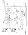
- switch 100 is a multi-protocol backbone system, which can process both of ATM cells IP traffic through its same switching fabric for customer premise equipment (CPE) 102 connected thereto.
- CPE customer premise equipment
- switch 100 provides CPEs 102 with access to its switching fabric 104 which is the core of switch 100.
- the switching fabric 104 provides a matrix allowing each CPE 102 to be connected to other devices connected to the switch 100.
- switch 100 allows scaling of the switching fabric capacity from 50 Gbps to 450 Gbps in increments of 14.4 Gbps by the insertion of additional shelves into the switch 100.
- CPEs 102 are connected to switch 100 via optical links 106 to I/O cards 108.
- I/O cards 108 provide the main input and output interface for conversion of communications between CPEs 102 and switch 100. I/O cards 108 provide minimal intelligent processing of communications passed therethrough.
- I/O cards 108 are connected to line cards 110 via midplane connections 112. Each line card 110 provides OC-192 functionality, bandwidth provisioning and ATM processing of cells between core of switch 100 and each CPE 102.
- Each line card is also connected to a fabric interface card (FIC) 114, which converts the signal to an optical signal and provides an interface for the communications with core 104.
- FIC fabric interface card
- the FIC can monitor and react to conditions reported by the line card 110.
- the FIC 114 may analyze and respond to failures reported by its line card 110, conduct sanity checks on data received from its line card 110 and send reporting messages to upstream shelf controller (described later).
- FICs 114 communicate with LPC 110 via midplane connections 116 and with core 104 via connections 118.
- the interface to core 104 for each FIC 114 is a switch access card (SAC) 120.
- SAC switch access card
- each I/O card 108, line card 110 and FIC 114 has a redundant counterpart, which is noted with the 'b' suffix. Accordingly, midplane connections 112 and 116 provide cross connections between the redundant and primary devices. For example, I/O cards 108 and 108b are connected to line cards 110 and 110b and line cards 110 and 110b are connected to FICs 114 and 114b.
- I/O card 108, line card 110 and FIC card 114 are grouped together in a single high speed peripheral shelf (HSPS) 122.
- HSPS 122 has two sets of I/O card groupings in slots 126 to provide redundancy between the groups of shelves.
- Switch 100 enables the use of multiple HSPSs 122 to provide enhanced expandability for the switch. Accordingly, with components grouped into shelves, a number of individual shelves can populate a switch 100 to provide modular functionality for switch 100.
- control signals for each shelf are also provided in modules, as necessary. This entails separate cabling of bundled control signals to each shelf at a communications point on each shelf. From the communication point, individual signals for individual components in the shelf are isolated and forwarded accordingly.
- Each I/O card 108 grouping in HSPS 122 must be controlled and co-ordinated with the other I/O cards 108 in HSPS 122.
- the embodiment provides a shelf controller 124 which controls operating aspects of shelves 122 connected to it.
- Such control operations include managing control and status functions for the shelf (such as slot monitoring and fan unit control), controlling FIC configuration for each line card 108, power rail monitoring and clock signal monitoring.
- Shelf controller 124 provides control connectivity via a specialized control service link (not shown). Data carried in the control service link controls downstream configuration and software downloading, time stamping, and synchronization of clocks.
- a terminal 128 is connected to switch 100 and runs controlling software which allows an operator to modify, and control the operation of, switch 100.
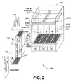
- switch 100 physically comprises a chassis 200, which houses HSPS 122 in cavity 202.
- HSPS 122 is contained in housing 204, which sits in a section of cavity 202.
- Shelf controller 124 is located above cavity 202.
- Each housing 204 contains a midplane 206, which is a physical support structure having connectors allowing line cards 110, FICs 114 and I/O cards 108 to be connected thereto. Connections 112 and 116 (see, Fig. 1) are provided by appropriate electrical connections between connectors in midplane 206.
- view 300 illustrates line card 110, I/O card 104, and FIC card 108 and midplane 206 for housing 204.
- Cards that have optical interfaces namely the I/O card 104 and FIC card 108, are located on one side of the midplane 206 and line card 110 is located on the other side of the midplane 206.
- Connectors 208 provide the physical interface for the cards to midplane 206. Specific connections between I/O card 104 and line card 110 and FIC card 108 are provided from the pins of various connectors 208 through midplane 206.
- switch 100 may be used to describe switch 100. Further, while the embodiment is described for switch 100, it will be appreciated that the system and method described herein may be adapted to any switching system.
- a mechanism for providing instructions from the shelf controller 124 to each line card 110 there is a need to have a mechanism for providing instructions from the shelf controller 124 to each line card 110.
- the remote line card was dumb, having no processing capabilities, e.g. a typical I/O card, or alternatively, all of the intelligence was placed on the line card, e.g. a typical line card or a FIC.
- the computing power required at the processing end becomes too large for the processing entity.
- the embodiment utilizes a system wherein computing is distributed between the FIC 114 and the shelf controller 124.
- the shelf controller 124 identifies what actions need to be taken by a FIC 114 and sends an appropriate instruction to the FIC 114.
- Each FIC 114 receives and processes its instruction and provides a suitable response to the shelf controller 124.
- the "master” element is the operative element in the shelf controller 124 and the “slave” element is the FIC 114.
- the term “master” is used interchangeably with “shelf controller” and the terms “slave” and “FIC” are also interchangeable for this specification. It will be appreciated that in other embodiments, the slave may be line card 110 or any other downstream device to the master.
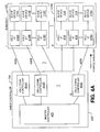
- the embodiment provides an egress communication system 400 for each HSPS 122 and the shelf controller 124.
- master controller 402 produces individual commands for each FIC 114 in each subshelf 122.
- Communication controllers 404 in shelf controller 124 receive each command for each FIC, or slave 114 and has them sent to each slave 114.
- Each HDLC communication controller 404 communicates with the FIC cards in slave 114 to request read/write access to FIC registers (not shown). For example, on a "read" command, master controller 402 may require status data about slave device 114a. In the distributed system, master controller 402 generates a read command for a particular flag of slave device 114a.
- Communication controller 404a receives the command from master controller 402 and has the command sent, ultimately, to slave device 114a, which receives the read command and processes it. After the read command is processed by slave device 114a, a response is generated and is sent back to master controller 402 through an ingress communication system 700, which provides an ingress communication link from each slave device 114a to controller 404a.
- Each controller 402 uses HDLC (High Level Data Link Control) protocol.
- HDLC is a known ISO and ITU-T standaridized link layer protocol used in point-to-point and multi-point communications.
- HDLC provides bit-oriented synchronous transmission of variable length frames.
- master 124 has unbalanced links with slaves 114. Accordingly, master 124 polls each slave 114 as necessary, and each polled slave 124 responds with information frames. The master 124 then acknowledges receipt of the frames from the slave. It will be appreciated that other communication protocols may be used. It will be appreciated that as there is a dedicated master for each slave, collectively, polling amongst all slaves can be done concurrently.
- the field length (in bits) is variable, depending on the HDLC control field.
- master 404 may request to a slave 114 to respond with a report of the status of all interrupts on slave card 114. Accordingly, the slave 114 would read all its registers that contain an interrupt status.
- An interrupt status may, for example, store the change of state information of an optical signal received by a pin diode.
- the slave 114 collects the register information and transmits it to master 402 per the designed communication protocol.
- this distributed messaging system overall provides a faster response time than have a master communicate with each slave device individually to and read their register status. Further, as each slave 114 only has knowledge of its local status, the master can collect all slave 114 information, then provide a response based on the net status of all slave registers. Referring to the earlier example of a read cycle, in the embodiment when master controller 402 requires data from a particular slave 114a, the control field is set to 00000000 by software in master controller 402 and the data field is defined as 32 bits containing an embedded 16 bit slave address as shown below: Data field Structure Read/ Write Address Bus Data Bus 1 15 16
- each communication controller 404 is individually hardwired to each slave 114 with links 405.
- multiplexing of signalling links is provided on both the ingress and egress directions. This is shown in Fig. 4B.
- each communications controller 404 receives instructions from master controller 402; each HDLC controller 404 is connected to multiplexer 406, producing one serial stream of data containing N channels of data on serial link 408.
- microprocessor 420 is a MPC 8260 Power PC PowerQUICC II programmable processor, available from Motorola, Inc.
- Microprocessor 420 has a programmable multichannel controller (MCC). The embodiment configures the MCC to provide the 16 communication controllers 404.
- MCC programmable multichannel controller
- microprocessor 420 also has an internal multiplexer 406 to produce single datastream 408 from the datastreams produced by the communication controllers 404.
- microprocessor 420 has a time slot assignor 421 which assigns a 8-bit timeslot from the TDM stream 408 to each of the controllers 404.
- the TDM stream contains sixteen 8 bits slots and operates at 8.25 MHz.
- the TDM stream in link 408 comprises 16 serial packets as shown below: Ch 0 Ch 1 Ch 16 HDLC 1 HDLC 2 .
- HDLC 16 It is desirable to have the HDLC timeslot at a minimum length (and thus the TDM stream at a minimum length) to decrease the latency on time -sensitive information in the TDM stream (such as interrupt status).
- Serial link 408 is provided to a group demultiplexer 410 which collectively groups the N channels into M channels 412.
- the demultiplexer 410 is embodied in a field programmable gate array (FPGA) 410.
- FPGA field programmable gate array
- Control for demultiplexer 410 is fixed and the demultiplexing does not change on different conditions.
- a bit counter signal and a channel counter signal are associated with the TDM stream.
- the bit counter signal and the channel counter signal are used by demultiplexer 410 to identify which bits from controllers 404 (or which bits from registers within FPGA 410) are inserted into which channel 412 at the correct frame.
- the FPGA 410 provides the following functions for microprocessor 420.
- the TDM stream 408 between the microprocessor 420 and FPGA 410 contains HDLC interfaces for FIC communications.
- the FPGA splits out TDM stream 408 into individual M TDM streams 412 for each of the HSPS sub-shelves 122.
- Control signals are embedded into the TDM stream 408 by FPGA 410.
- control signals for a FIC such as Line Card Presence, sub-shelf Number, FIC Interrupt Status, etc. may be transmitted between microprocessor 420 and slave 110 using the signal multiplexing scheme and FPGA 410.
- Microprocessor 420 provides a request for control signals for a FIC to FPGA 410 sent via 60x bus 422.
- FPGA 410 inserts an appropriate request in the appropriate timeslot for the requested slave 114 in the appropriate egress datastream 412.
- the targetted slave responds to the request and transmits the status to FPGA 410 via the ingress multiplexed stream.
- the results are stored in FPGA registers, which can be accessed by microprocessor 420 over bus 422.
- FPGA 410 may send a (maskable) interrupt to microprocessor 420 upon a status change of a control signal.
- FPGA 410 also performs a digital phase comparisons of the selected sources of timing from the shelf 124 and compares it with the system source sent to the shelf.
- TDM streams 412 connect the shelf controller to each of the four subshelves.
- the second TDM stream has sixteen timeslots operating at 8.25 MHz for each subshelf 122.
- Each M channel 412 is provided to each subself 122.
- Each of the four TDM substreams 412 (one to each sub-shelf) is a 16 timeslot frame operating at 8.25 MHz.
- TDM demultiplexer 414 utilizes the bit counter signal and the channel counter signal to determine which incoming part of the datastream on channel 412 is sent on which outgoing channel 416.
- demultiplexer 414 receives each channel 412 and produces N / M separate communication links 416, each of which is provided to each slave 114.
- Each slave device 114 has a HDLC interface module 418 which translates the HDLC encoded datastream 416 into a format which can be used by each slave 114.
- Each communication controller 404 has a timeslot in the TDM stream assigned to it. Similarly, each slave device 114 has a timeslot assigned to it for sending information to the master controller. Also, slave devices 114 can interrupt the master controller 124 at any time, if required.
- Having a dedicated communications controller 124 and corresponding control bandwidth for each slave device 114 ensures that control commands from the master controller 402 will be received by the slave devices 114 within a deterministic amount of time.
- each slave 114 generates a response or a signal destined for master controller 402; each slave 114 is to multiplexer 702, producing one serial stream of data containing N / M channels of data on serial link 704.
- Serial link 704 is provided to FPGA 410 which processes the information in the N / M channels 704 and provides an appropriate response, if necessary to master controller 402 via 60x bus 422.
- each slave device 114 Since each slave device 114 has its own timeslot during which it can communicate with the controller 402, information from the slave devices 110 will reach the master controller 402 within a defined amount of time. This allows bidirectional communications between the slave devices and the master controller to occur within a guaranteed latency. Accordingly, the embodiment allows a multishelf platform to detect a fault within 10 ms re-route around the fault within 50 ms, thereby conforming with requirements of a carrier-grade system.
- ingress multiplexing system 700 shares functional similarities with egress system 400.
- line cards 110 and I/O cards 108 generate some status signals as dc signals (not shown) which are provided to their CPLD 702.
- Each CPLD may embed these signals into the datastreams of its respective channel 704.
- FPGA 706 these embedded signals may be extracted and processed locally as needed. For example, they may be provided to other cards and systems associated with the FPGA 706.
- an ingress signalling system is also provided, which is similar to egress system 400, and is described later.
- each TDM bus is configured according to the following timing parameters.
- Each multiplexer has access to these timing signals.
- a common clock 602 operates at 8.25MHz and a frame pulse (FP) 604 operates at 64.45KHz.
- FP frame pulse
- the rising edge of FP 604 is aligned to the rising edge of clock 602.
- the FP defines a frame for a byte of transmitted information.
- timeslot signal 608 In order to provide the system with an earlier indication of the arrival of the next timeslot, timeslot count signal 608 in generated which is the same count signal as timeslot signal 606, but it is generated half a clock cycle earlier.
- bit position signal 610 As with the timeslot signal 606, as a mate to bit position signal 610, bit position count signal 612 is generated to provide the system with an earlier indication of the arrival of the next bit position.
- the first bit of the first timeslot (bit 7 of timeslot 0) is the MSB and will be coincident with the rising edge of FP 406. As there are 8 bits of data per timeslot, for data transactions involving data fields of more than 8 bits requires more than 1 TDM slot. Successive required slots are provided in the next TDM superframe.
- timing of signals sent between shelf controller 124 to each of subshelf 104 requires that no cells be dropped. Timing is handled in the following manner.
- each HDLC stream is transmitted at a clocking rate of 8.25 / 16 MHz, i.e. approximately 516 kHz, (or "R" for "Rate") to multiplexer 406.
- the collective datastream is clocked at 16 x R on serial link 408 to ensure that successive packets from each controller 404 in successive frames are not lost.
- the collective datastream on link 408 is provided to FPGA 410 which splits datastream into four separate datastreams on channels 412.
- Each separate datastream on each channel 412 contains datastreams for 4 HDLC slots destined for demultiplexers 414 associated with each subshelf 122.
- the clocking rate for each datastream on each channel 412 is still 16R. Accordingly, there is additional bandwidth available in each datastream in each channel 412, as only four slots are needed in the time frame which contains 16 time slots. Accordingly, 12 control slots are added to each datastream in each channel 412 by FPGA 410. The control slots contain information embedded into them by FPGA 410.
- each datastream is then passed to a CPLD within demultiplexer 414, which can extract some of the control information from the datastream for the FIC 114 or line card 110.
- the CPLD is located on midplane 206.
- the CPLD 414 further splits the datastream into four sub datastreams on channels 416, 1 channel 416 per slave device 114.
- a second CPLD (#2) can extract further control information from the received datastream.
- the received HDLC datastream is then clocked down to the original clocking rate of 8.25 MHz / 16, i.e. approximately 516 kHz (R).
- the clocked down data for data transmissions received by a slave device 114 contains the original information embedded in the TDM stream from its corresponding controller 404a.
- timing is maintained for the data rate and additional control information is provided in each datastream without occupying "true" bandwidth from the master-slave communication link.
- each HDLC link is dedicated, so if all 16 FIC 114 were reporting to their respective masters 404, the total maximum service time is still 188.8 us.
Landscapes
- Engineering & Computer Science (AREA)
- Computer Networks & Wireless Communication (AREA)
- Signal Processing (AREA)
- Time-Division Multiplex Systems (AREA)
Claims (11)
- Master- Slave Steuersystem für eine Nachrichtenvermittlung, bestehend aus:- einem Mastercontroller (402), der zum Erzeugen von Befehlen betrieben werden kann;- einer Vielzahl von Slaveeinrichtungen (114), verbunden mit dem besagten Mastercontroller (402), wobei jede Slaveeinrichtung (114) aus der besagten Vielzahl von Slaveeinrichtungen eingerichtet ist, die besagten Befehle zu empfangen und lokale Befehle als Antwort auf die besagten Befehle auszuführen, wobei das Systemdadurch gekennzeichnet ist, dass es weiterhin umfasst:- für jede Slaveeinrichtung (114)- einen Kommunikationscontroller (404), der so betrieben werden kann, dass er die besagten Befehle von dem besagten Mastercontroller (402) empfängt und Befehle über eine Nachrichtenverbindung (405) sendet, die mit dem besagten Kommunikationscontroller (404) und der besagten Slaveeinrichtung (114) verknüpft ist, wobei die besagte Nachrichtenverbindung (405) so betreibbar ist, dass sie die besagten Befehle von dem besagten Kommunikationscontroller (402) empfängt und die besagten Befehle zu einem Schnittstellenmodul (418) überträgt, das mit der besagten Nachrichtenverbindung (405) verbunden ist und so betrieben werden kann, dass es die besagten Befehle von der besagten Nachrichtenverbindung (405) empfängt und die besagten Befehle an die besagte Slaveeinrichtung (114) überträgt.
- Master- Slave Kommunikationssystem nach Anspruch 1, wobei:- der besagte Mastercontroller eingerichtet ist zum Empfangen von Statussignalen;- jede Slaveeinrichtung (114) aus der besagten Vielzahl von Slaveeinrichtungen eingerichtet ist, die besagten Statussignale für den besagten Mastercontroller (402) zu erzeugen; und- das besagte System für jede der besagten Slaveeinrichtungen (114) eine Kommunikationsanordnung für Signale umfasst, die zwischen dem besagten Mastercontroller (402) und der besagten Slaveeinrichtung (114) übertragen werden, bestehend aus:- dem besagten Kommunikationscontroller (404), verbunden mit dem besagten Mastercontroller (402), wobei der besagte Kommunikationscontroller (404) eingerichtet ist, die besagten Statussignale zu empfangen und Information, die sich auf die besagten Statussignale bezieht, für den besagten Mastercontroller (402) bereitzustellen, und- einer Nachrichtenverbindung, an die der besagte Kommunikationscontroller (404) und jede besagte Slaveeinrichtung (114) angeschlossen sind, wobei- die besagte Nachrichtenverbindung eingerichtet ist, die besagten Statussignale zu dem besagten Kommunikationscontroller (404) zu übertragen.
- Master- Slave Kommunikationssystem nach Anspruch 1 oder 2, weiterhin umfassend:- eine Nachrichtenverbindung signalabwärts, die ein Multiplexsignal umfasst, das die Kommunikation von jedem der besagten Kommunikationscontroller (404) zusammenfasst zu einem einzigen Multiplex-Signalstrom; und- Demultiplex- und Splittingmittel (410, 414) zum Bereitstellen eines Demultiplexsignals, abgeteilt aus dem besagten einzigen Multiplex- Signalstrom, für jede besagte Slaveeinrichtung (114).
- Master- Slave Kommunikationssystem nach einem der Ansprüche 1 bis 3, weiterhin umfassend:- eine Nachrichtenverbindung signalaufwärts, die ein Multiplexsignal umfasst, das die Kommunikation von jeder besagten Slaveeinrichtung (114) zusammenfasst zu einem zweiten einzigen Multiplex- Signalstrom; und- zweite Demultiplex- und Splittingmittel (421) zum Bereitstellen eines Demultiplexsignals, abgeteilt aus dem besagten zweiten einzigen Multiplex-Signalstrom, für jeden besagten Kommunikationscontroller (404).
- Master- Slave Kommunikationssystem nach Anspruch 4, weiterhin umfassend Mittel zur Synchronisation der Kommunikation, die in der besagten Nachrichtenverbindung signalabwärts und in der besagten Nachrichtenverbindung signalaufwärts übertragen wird
- Master- Slave Steuersystem für eine Nachrichtenvermittlung nach einem der Ansprüche 3 bis 5, wobei jeder Kommunikationscontroller (404), der zu einer entsprechenden Slaveeinrichtung (114) gehört, betreibbar ist, um ihnen Befehle entsprechend einem vorbestimmten Protoll zu senden, wobei das besagte System umfasst:- einen Zeitmultiplexer (421) TDM ( = Time Division Multiplex ), gekoppelt an jeden der Kommunikationscontroller (404) und betreibbar, einen TDM Datenstrom aus den Befehlen zu bilden, wobei im TDM Datenstrom jedem Kommunikationscontroller (404) ein entsprechender Zeitschlitz zugeordnet ist;- einen Zeitdemultiplexer (410), der mit dem Zeitmultiplexer (421) über eine serielle Verbindung (422) verbunden ist und betreibbar ist, um den TDM Datenstrom zu empfangen und Befehle von einem Kommunikationscontroller (404) an seine entsprechende Slaveeinrichtung (114) entsprechend dem diesem Kommunikationscontroller (404) zugeordneten Zeitschlitz zu senden, wobei die besagte Vielzahl von Slaveeinrichtungen (114) an den Zeitdemultiplexer (410, 414) angeschlossen ist und jede Slaveeinrichtung (114) eingerichtet ist, um Befehle entsprechend dem vorbestimmten Protokoll zu empfangen und auf besagte Befehle zu reagieren.
- Master- Slave Steuersystem für eine Nachrichtenvermittlung nach einem der Ansprüche 3 bis 6, wobei die besagte Nachrichtenverbindung signalabwärts folgendes umfasst:- eine TDM Anordnung, verbunden mit dem Kommunikationscontroller (404), wobei die besagte TDM Anordnung betreibbar ist, aus den besagten Befehlen einen TDM Datenstrom für eine serielle Verbindung zu bilden und wobei in dem besagten TDM Datenstrom ein Zeitschlitz zugeordnet ist einem Kommunikationspaar bestehend aus dem besagten Kommunikationscontroller (404) und der besagten wenigstens einen Slaveeinrichtung (114), und- einem TDM Demultiplexer (410, 414), verbunden mit der besagten seriellen Verbindung und der besagten wenigstens einen Slaveeinrichtung (114), wobei der besagte TDM Demultiplexer (410, 414) betreibbar ist, den besagten TDM Datenstrom zu empfangen, Nachrichten aus dem besagten Strom abzutrennen und besagte Nachricht an die besagte wenigstens eine Slaveeinrichtung (114) zu übertragen.
- Master- Slave Steuersystem für eine Nachrichtenvermittlung nach einem der Ansprüche 3 bis 7, wobei die besagte Nachrichtenverbindung signalaufwärts folgendes umfasst:- eine TDM Anordnung, verbunden mit der Slaveeinrichtung (114) wobei die besagte TDM Anordnung betreibbar ist, aus den besagten Statussignalen einen TDM Datenstrom für eine serielle Verbindung (708) zu bilden und wobei in dem besagten TDM Datenstrom ein Zeitschlitz zugeordnet ist einem Kommunikationspaar bestehend aus dem besagten Kommunikationscontroller (404) und der besagten Slaveeinrichtung (114), und- einem TDM Demultiplexer (406), verbunden mit der besagten seriellen Verbindung (708) und dem besagten Kommunikationscontroller (404), wobei der besagte TDM Demultiplexer (406) betreibbar ist, den besagten TDM Datenstrom zu empfangen, Nachrichten aus dem besagten Strom abzutrennen und besagte Nachricht an den besagten Kommunikationscontroller (404) zu übertragen.
- Master- Slave Steuersystem nach einem der Ansprüche 1 bis 8, wobei jede aus der besagten Vielzahl von Slaveeinrichtungen (114) auf einem getrennten Einschub (122, 124) des besagten Mastercontrollers (402) angeordnet werden kann.
- Master- Slave Steuersystem nach einem der Ansprüche 1 bis 9, wobei wenigstens eine aus der besagten Vielzahl von Slaveeinrichtungen (114) eine Fabric Schnittstellenkarte (114) ist.
- Master- Slave Steuersystem nach einem der Ansprüche 1 bis 10, wobei wenigstens eine aus der besagten Vielzahl von Slaveeinrichtungen (114) eine Netzkarte (110) ist.
Applications Claiming Priority (4)
| Application Number | Priority Date | Filing Date | Title |
|---|---|---|---|
| CA002357939A CA2357939A1 (en) | 2001-09-27 | 2001-09-27 | Master-slave communications system and method for a network element |
| CA2357939 | 2001-09-27 | ||
| US12430 | 2001-12-12 | ||
| US10/012,430 US7460482B2 (en) | 2001-09-27 | 2001-12-12 | Master-slave communications system and method for a network element |
Publications (2)
| Publication Number | Publication Date |
|---|---|
| EP1298867A1 EP1298867A1 (de) | 2003-04-02 |
| EP1298867B1 true EP1298867B1 (de) | 2006-05-31 |
Family
ID=25682735
Family Applications (1)
| Application Number | Title | Priority Date | Filing Date |
|---|---|---|---|
| EP02292370A Expired - Fee Related EP1298867B1 (de) | 2001-09-27 | 2002-09-26 | Master-Slave-Kommunikationssystem und -verfahren für ein Netzwerkelement |
Country Status (2)
| Country | Link |
|---|---|
| EP (1) | EP1298867B1 (de) |
| DE (1) | DE60211823T2 (de) |
Cited By (1)
| Publication number | Priority date | Publication date | Assignee | Title |
|---|---|---|---|---|
| WO2023006499A1 (de) | 2021-07-29 | 2023-02-02 | Basf Se | Verfahren zur kontinuierlichen destillation von acrylaten |
Families Citing this family (1)
| Publication number | Priority date | Publication date | Assignee | Title |
|---|---|---|---|---|
| CN109672566A (zh) * | 2019-01-04 | 2019-04-23 | 烽火通信科技股份有限公司 | 网元装置间的通信方法以及系统、应用 |
Family Cites Families (2)
| Publication number | Priority date | Publication date | Assignee | Title |
|---|---|---|---|---|
| JPH1056493A (ja) * | 1996-08-13 | 1998-02-24 | Nec Corp | 通信ネットワーク内における制御情報の転送装置 |
| US6452946B1 (en) * | 1999-06-04 | 2002-09-17 | Siemens Information And Communications Network, Inc. | Apparatus and method for improving performance in master and slave communications systems |
-
2002
- 2002-09-26 DE DE60211823T patent/DE60211823T2/de not_active Expired - Lifetime
- 2002-09-26 EP EP02292370A patent/EP1298867B1/de not_active Expired - Fee Related
Cited By (1)
| Publication number | Priority date | Publication date | Assignee | Title |
|---|---|---|---|---|
| WO2023006499A1 (de) | 2021-07-29 | 2023-02-02 | Basf Se | Verfahren zur kontinuierlichen destillation von acrylaten |
Also Published As
| Publication number | Publication date |
|---|---|
| DE60211823D1 (de) | 2006-07-06 |
| EP1298867A1 (de) | 2003-04-02 |
| DE60211823T2 (de) | 2007-05-24 |
Similar Documents
| Publication | Publication Date | Title |
|---|---|---|
| US7460482B2 (en) | Master-slave communications system and method for a network element | |
| US7209477B2 (en) | Multi-subshelf control system and method for a network element | |
| EP0559090B1 (de) | Netzwerkelement mit Querverbindungsmatrix und Server | |
| US6768745B1 (en) | Flexible SONET access and transmission system | |
| CN1193549C (zh) | 具有网格化底板的系统以及用于通过该系统传输数据的过程 | |
| US6160806A (en) | High density unit shelf with network interface cards and method | |
| US20030091035A1 (en) | Phase and frequency drift and jitter compensation in a distributed telecommunications switch | |
| CN1826742B (zh) | 同步电路、同步系统和用于使电路同步的方法 | |
| US20030189925A1 (en) | Transparent flexible concatenation | |
| JP2015130663A (ja) | ネットワークデバイスおよび情報送信方法 | |
| US20090262737A1 (en) | Communication apparatus, method and switch board for universal switching of multiple services | |
| US6580709B1 (en) | Sonet system and method which performs TSI functions on the backplane and uses PCM buses partitioned into 4-bit wide parallel buses | |
| US7653052B2 (en) | System and method for a control services link for a multi-shelf node in a communication switch | |
| US4719617A (en) | Full service voice/data system | |
| US20040162919A1 (en) | Method and apparatus for backplane distribution using asynchronous transfer mode | |
| US6788703B2 (en) | DS0 on ATM, mapping and handling | |
| US6885661B1 (en) | Private branch exchange built using an ATM Network | |
| EP1298867B1 (de) | Master-Slave-Kommunikationssystem und -verfahren für ein Netzwerkelement | |
| US6801548B1 (en) | Channel ordering for communication signals split for matrix switching | |
| EP1298852B1 (de) | Multi-subshelf Steuersystem und Verfahren für ein Netzelement | |
| JPH1188332A (ja) | 同期ディジタルインタフェースへのセル多重装置及び方法 | |
| US7095735B2 (en) | System and method for a control services link for a multi-shelf node in a communication switch | |
| EP0757882B1 (de) | Zeitschaltersystem | |
| JP3578085B2 (ja) | ハイブリットスイッチ装置 | |
| US7450493B1 (en) | System and method of forwarding K-bytes between optical cards in a communications system |
Legal Events
| Date | Code | Title | Description |
|---|---|---|---|
| PUAI | Public reference made under article 153(3) epc to a published international application that has entered the european phase |
Free format text: ORIGINAL CODE: 0009012 |
|
| AK | Designated contracting states |
Kind code of ref document: A1 Designated state(s): AT BE BG CH CY CZ DE DK EE ES FI FR GB GR IE IT LI LU MC NL PT SE SK TR |
|
| AX | Request for extension of the european patent |
Extension state: AL LT LV MK RO SI |
|
| 17P | Request for examination filed |
Effective date: 20031002 |
|
| 17Q | First examination report despatched |
Effective date: 20031110 |
|
| AKX | Designation fees paid |
Designated state(s): DE ES FR GB IT |
|
| GRAP | Despatch of communication of intention to grant a patent |
Free format text: ORIGINAL CODE: EPIDOSNIGR1 |
|
| GRAS | Grant fee paid |
Free format text: ORIGINAL CODE: EPIDOSNIGR3 |
|
| GRAA | (expected) grant |
Free format text: ORIGINAL CODE: 0009210 |
|
| AK | Designated contracting states |
Kind code of ref document: B1 Designated state(s): DE ES FR GB IT |
|
| REG | Reference to a national code |
Ref country code: GB Ref legal event code: FG4D |
|
| REF | Corresponds to: |
Ref document number: 60211823 Country of ref document: DE Date of ref document: 20060706 Kind code of ref document: P |
|
| PG25 | Lapsed in a contracting state [announced via postgrant information from national office to epo] |
Ref country code: ES Free format text: LAPSE BECAUSE OF FAILURE TO SUBMIT A TRANSLATION OF THE DESCRIPTION OR TO PAY THE FEE WITHIN THE PRESCRIBED TIME-LIMIT Effective date: 20060911 |
|
| PGFP | Annual fee paid to national office [announced via postgrant information from national office to epo] |
Ref country code: GB Payment date: 20060921 Year of fee payment: 5 |
|
| ET | Fr: translation filed | ||
| PLBE | No opposition filed within time limit |
Free format text: ORIGINAL CODE: 0009261 |
|
| STAA | Information on the status of an ep patent application or granted ep patent |
Free format text: STATUS: NO OPPOSITION FILED WITHIN TIME LIMIT |
|
| 26N | No opposition filed |
Effective date: 20070301 |
|
| GBPC | Gb: european patent ceased through non-payment of renewal fee |
Effective date: 20070926 |
|
| PG25 | Lapsed in a contracting state [announced via postgrant information from national office to epo] |
Ref country code: GB Free format text: LAPSE BECAUSE OF NON-PAYMENT OF DUE FEES Effective date: 20070926 |
|
| REG | Reference to a national code |
Ref country code: FR Ref legal event code: CD Owner name: ALCATEL-LUCENT CANADA INC Effective date: 20130723 |
|
| REG | Reference to a national code |
Ref country code: FR Ref legal event code: GC Effective date: 20130820 |
|
| REG | Reference to a national code |
Ref country code: FR Ref legal event code: RG Effective date: 20141015 |
|
| REG | Reference to a national code |
Ref country code: FR Ref legal event code: PLFP Year of fee payment: 14 |
|
| REG | Reference to a national code |
Ref country code: FR Ref legal event code: PLFP Year of fee payment: 15 |
|
| REG | Reference to a national code |
Ref country code: FR Ref legal event code: PLFP Year of fee payment: 16 |
|
| REG | Reference to a national code |
Ref country code: FR Ref legal event code: PLFP Year of fee payment: 17 |
|
| PGFP | Annual fee paid to national office [announced via postgrant information from national office to epo] |
Ref country code: FR Payment date: 20180924 Year of fee payment: 17 Ref country code: IT Payment date: 20180925 Year of fee payment: 17 Ref country code: DE Payment date: 20180920 Year of fee payment: 17 |
|
| REG | Reference to a national code |
Ref country code: DE Ref legal event code: R119 Ref document number: 60211823 Country of ref document: DE |
|
| PG25 | Lapsed in a contracting state [announced via postgrant information from national office to epo] |
Ref country code: DE Free format text: LAPSE BECAUSE OF NON-PAYMENT OF DUE FEES Effective date: 20200401 |
|
| PG25 | Lapsed in a contracting state [announced via postgrant information from national office to epo] |
Ref country code: IT Free format text: LAPSE BECAUSE OF NON-PAYMENT OF DUE FEES Effective date: 20190926 |
|
| PG25 | Lapsed in a contracting state [announced via postgrant information from national office to epo] |
Ref country code: FR Free format text: LAPSE BECAUSE OF NON-PAYMENT OF DUE FEES Effective date: 20190930 |