EP1298519A2 - Tragbarer Computer - Google Patents
Tragbarer Computer Download PDFInfo
- Publication number
- EP1298519A2 EP1298519A2 EP02019331A EP02019331A EP1298519A2 EP 1298519 A2 EP1298519 A2 EP 1298519A2 EP 02019331 A EP02019331 A EP 02019331A EP 02019331 A EP02019331 A EP 02019331A EP 1298519 A2 EP1298519 A2 EP 1298519A2
- Authority
- EP
- European Patent Office
- Prior art keywords
- slide
- module
- plug
- modules
- portable computer
- Prior art date
- Legal status (The legal status is an assumption and is not a legal conclusion. Google has not performed a legal analysis and makes no representation as to the accuracy of the status listed.)
- Withdrawn
Links
Images
Classifications
-
- G—PHYSICS
- G06—COMPUTING OR CALCULATING; COUNTING
- G06F—ELECTRIC DIGITAL DATA PROCESSING
- G06F1/00—Details not covered by groups G06F3/00 - G06F13/00 and G06F21/00
- G06F1/16—Constructional details or arrangements
- G06F1/1613—Constructional details or arrangements for portable computers
-
- G—PHYSICS
- G06—COMPUTING OR CALCULATING; COUNTING
- G06F—ELECTRIC DIGITAL DATA PROCESSING
- G06F1/00—Details not covered by groups G06F3/00 - G06F13/00 and G06F21/00
- G06F1/16—Constructional details or arrangements
- G06F1/1613—Constructional details or arrangements for portable computers
- G06F1/1633—Constructional details or arrangements of portable computers not specific to the type of enclosures covered by groups G06F1/1615 - G06F1/1626
- G06F1/1656—Details related to functional adaptations of the enclosure, e.g. to provide protection against EMI, shock, water, or to host detachable peripherals like a mouse or removable expansions units like PCMCIA cards, or to provide access to internal components for maintenance or to removable storage supports like CDs or DVDs, or to mechanically mount accessories
Definitions
- the invention relates to a portable computer with a housing with two slots next to each other for Inclusion of one plug-in module each, the plug-in modules by means of a lock in an insertion position can be held and to remove the plug-in modules the lock can be released.
- plug-in modules In portable computers there are often components via plug-in modules realized so that they are interchangeable.
- Such Modules can include hard drives, floppy drives, CD drives or special interface cards.
- the Inserts are usually designed so that after the Insertion of a slide-in module in the slide-in position locked. The locking can be done by a special mechanism be solved when the plug-in module is removed again shall be.
- the object of the invention is therefore, in portable computers, two slots are arranged side by side in the housing space-saving locking and unlocking of the plug-in modules to enable.
- This task is accomplished by a portable computer at the outset mentioned type, which is characterized that a locking device is provided for Lock acts on both slots and the to Unlocked by a common actuator on one or can affect the other slot.
- the advantage of the arrangement according to the invention is that that a single locking device for two slots, that means above all only one actuator the side of the housing is sufficient to unlock the plug-in modules to effect. The space requirement is thus reduced for the unlocking device of the slots.
- a Slider provided, the outer ends of which are in the slots protrude and there for locking with recesses of the Interacting plug-in modules.
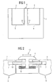
- FIG. 1 is a top view of a portable computer shown. Inside the portable computer are two Insert slots 8 and 9 are provided in the insert modules 2 and 3 can be inserted. In the exemplary embodiment operation of the lock from the front of the housing, in the representation of FIG. 1 from above.
- FIG. 2 shows a locking device according to the invention shown by which the plug-in modules 2 and 3 in one Slot position locked in slots 8 and 9 and can also be unlocked again.
- a Slider 5 provided in the areas of the two slots 8 and 9 protrudes.
- the slide 5 is by a Spring 6 held in a central position, which is the Represents rest position.
- the slide is with a Actuator button 4 connected to the outside of the housing lies and is therefore accessible to a user. By the Operating button 4, the slide can be perpendicular to the direction of insertion the plug-in modules 2 and 3 are moved.
- the other plug-in module 3 and the other outer end section 11 of the slider 5 are designed in the same way. So would also when inserting the second plug-in module 3 Bevel 12 exert a force on slide 5.
- the recess 7 of the first insertion module 2 is deeper than that in the first plug-in module 2 engaging end section 10. Only then can the slide 5 so far in the other direction that the second Insert module 3 can be plugged in unhindered.
- the Insert position is also the insert module 3 by the Slider 5 held in this position, so it is locked. This is the operating situation that Figure 2 shows.
- plug-in modules 2 and 3 have a locking as well as an unlocking mechanism without using two control buttons have to.
- the for locking and unlocking the plug-in modules 2 and 3 proposed locking device is thus easier than the provision of two such devices as with the state of the art, which on the one hand saves costs as well as saving space on the surface of the housing.
- the slide is not rigid, but the end sections are resilient to the central part of the Connected slide.
- the recesses in the plug-in modules 2 and 3 are deeper than the depth of penetration of the end sections 10 and 11 of the slide 5 in the embodiment of Figure 2.
- the invention is not based on the exemplary embodiments described limited. So are. arrangements also conceivable in which a movement of the operating button is not different from that to unlock the module away, but executed towards this must become.
- the push button can also be on another side of the housing be provided. Instead of the slider could also a lever mechanism can be used. A variety of others Possibilities lie within the scope of the professional ability.
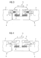
- FIG. 4 In a modified version, shown in Figure 4 is not the plug-in modules 2 and 3 with a bevel provided, but the end sections 10 and 11.
- a plug-in module 2 or 3 which in this version the invention does not have to be chamfered this first with the bevel 14 of the respective end section of the slide 5 in contact.
- the slide 5 is also pushed back in this modification, so that the plug-in module 2 or 3 fully inserted in slot 8 or 9 can be.
Landscapes
- Engineering & Computer Science (AREA)
- Computer Hardware Design (AREA)
- Theoretical Computer Science (AREA)
- General Engineering & Computer Science (AREA)
- Human Computer Interaction (AREA)
- Physics & Mathematics (AREA)
- General Physics & Mathematics (AREA)
- Details Of Connecting Devices For Male And Female Coupling (AREA)
- Connector Housings Or Holding Contact Members (AREA)
Abstract
Description
- Figur 1
- einen tragbaren Computer in einer schematischen Darstellung mit der Anordnung von Einschubplätzen,
- Figur 2
- ein erstes Ausführungsbeispiel einer Verriegelungsvorrichtung nach der Erfindung,
- Figur 3
- ein zweites Ausführungsbeispiel einer Verriegelungsvorrichtung nach der Erfindung und
- Figur 4
- eine Abwandlung des Ausführungsbeispiels von Figur 2.
- 1
- Gehäuse
- 2
- erstes Einschubmodul
- 3
- zweites Einschubmodul
- 4
- Betätiger
- 5
- Schieber
- 6
- Feder
- 7
- Ausnehmung
- 8
- erster Einschubplatz
- 9
- zweiter Einschubplatz
- 10
- Endabschnitt
- 11
- Endabschnitt
- 12
- Anschrägung
- 13
- Verriegelungsvorrichtung
- 14
- Anschrägung
Claims (4)
- Tragbarer Computer mit
einem Gehäuse (1) mit zwei nebeneinander angeordneten Einschubplätzen (8, 9) zur Aufnahme von jeweils einem Einschubmodul (2, 3), wobei die Einschubmodule (2, 3) mittels einer Verriegelung in einer Einschubposition gehalten werden können und zur Entnahme der Einschubmodule (2, 3) die Verriegelung lösbar ist,
dadurch gekennzeichnet, daß
eine Verriegelungsvorrichtung (13) vorgesehen, die zur Verriegelung auf beider Einschubplätze (8, 9) einwirkt und die zur Entriegelung durch einen gemeinsamen Betätiger (4) auf den einen oder den anderen Einschubplatz (8, 9) einwirken kann. - Tragbarer Computer nach Anspruch 1,
dadurch gekennzeichnet, daß
die Verriegelungsvorrichtung (13) einen senkrecht zur Einschubrichtung beweglichen Schieber (5) aufweist, dessen Ruhelage durch eine Rückstellvorrichtung (6) in einer mittigen Position festgelegt ist, wobei äußere Endabschnitte (10, 11) des Schiebers (5) jeweils in einen Einschubplatz (8, 9) hineinragen und zur Verrastung jeweils in eine Ausnehmung (7) eines Einschubmoduls (2, 3) eingreifen, wobei die Ausnehmungen (7) mindestens doppelt so tief sind wie die Länge der in der Ruhelage in die Ausnehmung (7) eingreifenden Endabschnitte (10, 11) des Schiebers (5). - Tragbarer Computer nach Anspruch 1,
dadurch gekennzeichnet, daß
die Verriegelungsvorrichtung (13) einen senkrecht zur Einschubrichtung beweglichen Schieber (5) aufweist, dessen Ruhelage durch eine Rückstellvorrichtung (6) in einer mittigen Position festgelegt ist, wobei äußere Endabschnitte (10, 11) des Schiebers (5) jeweils in einen Einschubplatz (8, 9) hineinragen und zur Verrastung jeweils in eine Ausnehmung (7) eines Einschubmoduls (2, 3) eingreifen, wobei die Endabschnitte (10, 11) federnd mit einem mittleren Abschnitt des Schiebers verbunden sind. - Tragbarer Computer nach Anspruch 2 oder 3,
dadurch gekennzeichnet, daß
der Schieber (5) mit einem außerhalb des Gehäuses angeordneten Knopf verbunden ist, durch den der Schieber (5) betätigbar ist.
Applications Claiming Priority (2)
| Application Number | Priority Date | Filing Date | Title |
|---|---|---|---|
| DE10147790 | 2001-09-27 | ||
| DE2001147790 DE10147790B4 (de) | 2001-09-27 | 2001-09-27 | Tragbarer Computer |
Publications (2)
| Publication Number | Publication Date |
|---|---|
| EP1298519A2 true EP1298519A2 (de) | 2003-04-02 |
| EP1298519A3 EP1298519A3 (de) | 2008-11-05 |
Family
ID=7700569
Family Applications (1)
| Application Number | Title | Priority Date | Filing Date |
|---|---|---|---|
| EP02019331A Withdrawn EP1298519A3 (de) | 2001-09-27 | 2002-08-28 | Tragbarer Computer |
Country Status (3)
| Country | Link |
|---|---|
| EP (1) | EP1298519A3 (de) |
| DE (1) | DE10147790B4 (de) |
| TW (1) | TWI232366B (de) |
Families Citing this family (1)
| Publication number | Priority date | Publication date | Assignee | Title |
|---|---|---|---|---|
| DE102007051600B3 (de) * | 2007-10-29 | 2009-06-18 | Fujitsu Siemens Computers Gmbh | Tragbares Computersystem |
Family Cites Families (3)
| Publication number | Priority date | Publication date | Assignee | Title |
|---|---|---|---|---|
| US5680126A (en) * | 1992-06-29 | 1997-10-21 | Elonex I.P. Holdings, Ltd. | Modular portable computer |
| US5793607A (en) * | 1995-10-30 | 1998-08-11 | International Business Machines Corporation | Ejection mechanism for PC cards |
| US5757616A (en) * | 1996-10-31 | 1998-05-26 | Hewlett-Packard Company | Physical security system for portable computer |
-
2001
- 2001-09-27 DE DE2001147790 patent/DE10147790B4/de not_active Expired - Fee Related
-
2002
- 2002-08-28 EP EP02019331A patent/EP1298519A3/de not_active Withdrawn
- 2002-09-20 TW TW91121629A patent/TWI232366B/zh active
Also Published As
| Publication number | Publication date |
|---|---|
| DE10147790B4 (de) | 2005-06-23 |
| DE10147790A1 (de) | 2003-04-24 |
| TWI232366B (en) | 2005-05-11 |
| EP1298519A3 (de) | 2008-11-05 |
Similar Documents
| Publication | Publication Date | Title |
|---|---|---|
| DE69232081T2 (de) | Anschlussvorrichtung | |
| DE3873618T2 (de) | Vorrichtung auf einer kartenfuehrungsleiste zum einstecken und herausziehen. | |
| DE69317374T2 (de) | Steckverbinderaufbau | |
| EP0899818B1 (de) | Elektrische Anschlussklemme, insbesondere für den Einsatz auf Leiterplatten | |
| DE69416099T2 (de) | Selbsteinstellende Vorrichtung zum Einsetzen und Herausziehen von Leiterplatten | |
| DE69832855T2 (de) | Kartenverbinder | |
| DE202019105075U1 (de) | Anschlussklemme für Leiter | |
| DE1238534B (de) | Schaltvorrichtung fuer Kontaktfederleisten | |
| DE10392590T5 (de) | Kabelverbinder-Verriegelungsanordnung | |
| EP2625747B1 (de) | Zusatzanschlussstecker | |
| DE60007149T2 (de) | Bistabile elektrische Anschlussklemme | |
| DE10327948A1 (de) | Schaltungsplatinen-Hebelwirkungsmechanismus | |
| DE4026155A1 (de) | Riegelbetaetigungsvorrichtung fuer tueren o. dgl. | |
| DE69223994T2 (de) | Mechanisches kartenschloss | |
| EP1420330A2 (de) | Stromversorgung für ein elektrisches Gerät | |
| DE10147790B4 (de) | Tragbarer Computer | |
| DE3338713A1 (de) | Sicherheitsschloss | |
| EP4444971B1 (de) | Schlüssel für ein zylinderschloss sowie zylinderschloss | |
| DE19530844B4 (de) | Elektrischer Steckverbinder mit Betätigungsschieber | |
| EP0998865B1 (de) | Auszugsführung mit Verriegelung | |
| DE19709198B4 (de) | Steckeranordnung mit einem Betätigungsschieber | |
| DE69103182T2 (de) | Schloss, welches mittels einer Karte mit verschiedenen Löchern betätigbar ist. | |
| EP1126557A2 (de) | Elektrischer Steckverbinder | |
| DE202017107275U1 (de) | Verriegelungsvorrichtung für elektronische Geräte | |
| DE19530335B4 (de) | Steckeranordnung |
Legal Events
| Date | Code | Title | Description |
|---|---|---|---|
| PUAI | Public reference made under article 153(3) epc to a published international application that has entered the european phase |
Free format text: ORIGINAL CODE: 0009012 |
|
| AK | Designated contracting states |
Kind code of ref document: A2 Designated state(s): AT BE BG CH CY CZ DE DK EE ES FI FR GB GR IE IT LI LU MC NL PT SE SK TR Designated state(s): AT BE BG CH CY CZ DE DK EE ES FI FR GB GR IE IT LI LU MC NL PT SE SK TR |
|
| AX | Request for extension of the european patent |
Extension state: AL LT LV MK RO SI |
|
| RAP1 | Party data changed (applicant data changed or rights of an application transferred) |
Owner name: FUJITSU SIEMENS COMPUTERS GMBH |
|
| PUAL | Search report despatched |
Free format text: ORIGINAL CODE: 0009013 |
|
| AK | Designated contracting states |
Kind code of ref document: A3 Designated state(s): AT BE BG CH CY CZ DE DK EE ES FI FR GB GR IE IT LI LU MC NL PT SE SK TR |
|
| AX | Request for extension of the european patent |
Extension state: AL LT LV MK RO SI |
|
| AKX | Designation fees paid | ||
| STAA | Information on the status of an ep patent application or granted ep patent |
Free format text: STATUS: THE APPLICATION IS DEEMED TO BE WITHDRAWN |
|
| 18D | Application deemed to be withdrawn |
Effective date: 20090507 |
|
| REG | Reference to a national code |
Ref country code: DE Ref legal event code: 8566 |