EP1296157A2 - Method for calibrating radar signals from the sub-apertures of the antenna of a two-channel SAR/MTI radar system - Google Patents
Method for calibrating radar signals from the sub-apertures of the antenna of a two-channel SAR/MTI radar system Download PDFInfo
- Publication number
- EP1296157A2 EP1296157A2 EP02016541A EP02016541A EP1296157A2 EP 1296157 A2 EP1296157 A2 EP 1296157A2 EP 02016541 A EP02016541 A EP 02016541A EP 02016541 A EP02016541 A EP 02016541A EP 1296157 A2 EP1296157 A2 EP 1296157A2
- Authority
- EP
- European Patent Office
- Prior art keywords
- sum
- difference
- phase
- difference channel
- calculation
- Prior art date
- Legal status (The legal status is an assumption and is not a legal conclusion. Google has not performed a legal analysis and makes no representation as to the accuracy of the status listed.)
- Granted
Links
Images

Classifications
-
- G—PHYSICS
- G01—MEASURING; TESTING
- G01S—RADIO DIRECTION-FINDING; RADIO NAVIGATION; DETERMINING DISTANCE OR VELOCITY BY USE OF RADIO WAVES; LOCATING OR PRESENCE-DETECTING BY USE OF THE REFLECTION OR RERADIATION OF RADIO WAVES; ANALOGOUS ARRANGEMENTS USING OTHER WAVES
- G01S13/00—Systems using the reflection or reradiation of radio waves, e.g. radar systems; Analogous systems using reflection or reradiation of waves whose nature or wavelength is irrelevant or unspecified
- G01S13/88—Radar or analogous systems specially adapted for specific applications
- G01S13/89—Radar or analogous systems specially adapted for specific applications for mapping or imaging
- G01S13/90—Radar or analogous systems specially adapted for specific applications for mapping or imaging using synthetic aperture techniques, e.g. synthetic aperture radar [SAR] techniques
- G01S13/9021—SAR image post-processing techniques
- G01S13/9029—SAR image post-processing techniques specially adapted for moving target detection within a single SAR image or within multiple SAR images taken at the same time
-
- G—PHYSICS
- G01—MEASURING; TESTING
- G01S—RADIO DIRECTION-FINDING; RADIO NAVIGATION; DETERMINING DISTANCE OR VELOCITY BY USE OF RADIO WAVES; LOCATING OR PRESENCE-DETECTING BY USE OF THE REFLECTION OR RERADIATION OF RADIO WAVES; ANALOGOUS ARRANGEMENTS USING OTHER WAVES
- G01S13/00—Systems using the reflection or reradiation of radio waves, e.g. radar systems; Analogous systems using reflection or reradiation of waves whose nature or wavelength is irrelevant or unspecified
- G01S13/88—Radar or analogous systems specially adapted for specific applications
- G01S13/89—Radar or analogous systems specially adapted for specific applications for mapping or imaging
- G01S13/90—Radar or analogous systems specially adapted for specific applications for mapping or imaging using synthetic aperture techniques, e.g. synthetic aperture radar [SAR] techniques
- G01S13/904—SAR modes
- G01S13/9092—SAR modes combined with monopulse techniques
-
- G—PHYSICS
- G01—MEASURING; TESTING
- G01S—RADIO DIRECTION-FINDING; RADIO NAVIGATION; DETERMINING DISTANCE OR VELOCITY BY USE OF RADIO WAVES; LOCATING OR PRESENCE-DETECTING BY USE OF THE REFLECTION OR RERADIATION OF RADIO WAVES; ANALOGOUS ARRANGEMENTS USING OTHER WAVES
- G01S7/00—Details of systems according to groups G01S13/00, G01S15/00, G01S17/00
- G01S7/02—Details of systems according to groups G01S13/00, G01S15/00, G01S17/00 of systems according to group G01S13/00
- G01S7/40—Means for monitoring or calibrating
- G01S7/4004—Means for monitoring or calibrating of parts of a radar system
- G01S7/4021—Means for monitoring or calibrating of parts of a radar system of receivers
-
- G—PHYSICS
- G01—MEASURING; TESTING
- G01S—RADIO DIRECTION-FINDING; RADIO NAVIGATION; DETERMINING DISTANCE OR VELOCITY BY USE OF RADIO WAVES; LOCATING OR PRESENCE-DETECTING BY USE OF THE REFLECTION OR RERADIATION OF RADIO WAVES; ANALOGOUS ARRANGEMENTS USING OTHER WAVES
- G01S13/00—Systems using the reflection or reradiation of radio waves, e.g. radar systems; Analogous systems using reflection or reradiation of waves whose nature or wavelength is irrelevant or unspecified
- G01S13/02—Systems using reflection of radio waves, e.g. primary radar systems; Analogous systems
- G01S13/50—Systems of measurement based on relative movement of target
- G01S13/52—Discriminating between fixed and moving objects or between objects moving at different speeds
- G01S13/522—Discriminating between fixed and moving objects or between objects moving at different speeds using transmissions of interrupted pulse modulated waves
- G01S13/524—Discriminating between fixed and moving objects or between objects moving at different speeds using transmissions of interrupted pulse modulated waves based upon the phase or frequency shift resulting from movement of objects, with reference to the transmitted signals, e.g. coherent MTi
Definitions
- the invention relates to a method for calibrating the radar signals to the Subapertures of the antenna of a two-channel SAR (synthetic aperture) / MTI (moving Target Indication) radar system according to the preamble of claim 1.
- the sum channel signal is used to create so-called radar bottom maps.
- the sum channel signal is used to carry out detection and detection (indication) of moving targets in images similar to radar floor maps.
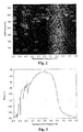
- 2 shows a typical distance Doppler image in the summation channel after the detection of fixed and moving targets.
- the signal powers are plotted over the distance gates and the normalized frequency f / f s .
- the diagram shows clearly that the area of the antenna light spot (bright area), also referred to as the main lobe clutter, is shifted from the Doppler frequency position to zero due to a change in the relative geometry during the illumination time.
- the circles shown in the picture indicate the detected fixed and moving targets.
- the Doppler frequency position of the main lobe clutter is exemplarily at a normalized frequency of 0.2.
- the differential channel signal does not continue is used, the difference channel signal is used in the corresponding MIT radar signal processing this requires, on the one hand, a separation of fixed and moving targets to achieve and on the other hand a repositioning, with respect to the Doppler frequency to carry shifted, moving targets.
- One method for suppressing fixed targets is, for example, the so-called STAP (Space Time Adaptive Processing) method.
- STAP Space Time Adaptive Processing
- the sub-aperture channel signals are exactly the same in amplitude and differ in phase only by a phase value caused by the relative geometry and antenna arrangement.
- To reposition the moving target it is also necessary to compensate for different phase differences between the sub-aperture channel signals, which lead to incorrect positioning.
- a common method for determining the compensation factors of amplitude and phase is the use of defined test signals which are fed into the waveguide part or are radiated in via the antenna. This happens before the radar antenna is actually used.
- the sum and difference channel signals behind the waveguide part are then calculated back into the input signals upstream of the waveguide part, that is to say into the signals of the two sub-aperture channels. If the correction factors have been correctly determined, the two signals are identical.
- the factors are stored in the memory of the digital signal processing and read out from it during use of the radar antenna. Such a method is described by Shunjun W. et al. in "Adaptive Channel Equalization for Space-Time Adaptive Processing"; IEEE International Radar Conference 1995.
- phase difference between the sum and difference channels is determined with the phase correction factor kanal 0 .
- the area of the greatest energy in the sum and difference channel MTI image is preferably used to determine the phase correction factor ⁇ 0 .
- This area of greatest energy is in particular the area of the main lobe of the antenna.
- the calculation of the Doppler frequency position of the main lobe clutter in the first calculation step can use the method in the unpublished patent application DE 101 24 865.2.
- This area is according to the invention adaptively estimated the radar data.
- the correction of the sum and difference channel signals X S (r, t), X D (r, t) in the second calculation step is also referred to as the so-called deramping method.
- the bandwidth reduction is used to reduce the number of signal values, a so-called sampling rate reduction. This is advantageous a reduction in computing time with the same spectral resolution, or advantageous an increase in the spectral resolution with an increase in the number of reduced ones Signal values.
- the sampling rate reduction is carried out in the fourth calculation step.
- the sum and difference channel time signals are located within a distance cell several point targets that differ in amplitude and phase. However, these cannot be resolved in the time signal.
- a transformation of the filtered Sum and difference channel signals in the spectral range the so-called Doppler frequency range carried out.
- the transformation is advantageously carried out using a windowed Fourier Fast Transformation (FFT). It follows that the individual point targets with regard to their frequency, i.e. the time derivative of the Phase can be distinguished.
- FFT windowed Fourier Fast Transformation
- An FFT can be viewed as an arrangement of several frequency subbands become.
- Each frequency subband has an attenuation of approx. 14 dB, corresponding to the impulse response of a rectangular window. It means that Amplitudes of the neighboring frequency band with an attenuation of approx. 14 dB also be allowed through.
- the time signals are advantageous by means of a window function high blocking attenuation, this results in an almost unadulterated spectral signal in every frequency band.
- FIG. 3 shows an example of the phase difference between the sum and difference channel spectrum in the main lobe clutter region, the Doppler frequency position of the main lobe clutter according to FIG. 2 being 0.2.
- FIG. 3 shows a phase difference of -110 ° between the sum and difference channel spectrum for the mean Doppler frequency position of the main lobe clutter.
- This phase difference which can be 90 °, for example, depending on the design of the MagicT, is corrected according to the invention by means of the phase correction factor ⁇ 0 in the spectrum.
- the arithmetic mean of the difference phase values is then calculated in the eighth calculation step within the Doppler frequency position range of the main lobe clutter determined in the first calculation step.
- This mean corresponds to the phase correction factor ⁇ 0 .
- FIG. 4 shows an enlarged section around the Doppler frequency position of the main lobe clutter from FIG. 3.
- a further curve is drawn in, which corresponds to the course of the phase difference between the sum and difference channel spectrum corrected by the phase correction factor a 0 .
- This corrected curve has a phase difference of 0 ° between the sum and difference channel spectrum at the Doppler frequency position of the main lobe clutter.
- the frequency spectra for the two subaperture channels are determined according to equations (1) and (2) by means of the estimated phase correction factor admiri 0, the amplitude correction factor a 0 being set to 1.
- the power density spectra are calculated from the complex frequency spectra and these are advantageously geometrically averaged over a predeterminable selection of distance gates, ie the mean value of the logarithmic powers is calculated.
- the amplitude correction factor a 0 estimated in the second, third and fourth calculation step thus indicates by how much the power density spectra of the two sub-aperture channel spectra constantly deviate from one another, at least in the region of the main lobe clutter.
- the stabilization of the Estimation of the constant phase and amplitude correction factors recursively from Signal pulse package to signal pulse package.
- a frequency distribution of the Estimates are calculated and the value with the greatest frequency is used as an estimate.
- An advantage of the invention is that the sum and difference channel by means of digital Signal processing can be calculated back into the individual channels of the subaperture, without having to make any changes to the antenna (front end). These calculations are done during normal antenna operation, without having to interrupt the coherent signal processing.
- An essential one The advantage of the invention is that no test signal is required for the calculation, but this happens on the radar data itself. In addition, the invention provides Very good procedure even with a bad signal / noise ratio Results.
- Another advantage is that for the method according to the invention no knowledge of the Synchronous properties of the channels is required. If the synchronization differences of the channels are time-dependent, this is due to the adaptivity of the invention Method taken into account by applying the method in every nth calculation step and the estimates are used with the greatest probability.
- the method according to the invention can also be applied to signals other than radar signals transfer.
Landscapes
- Engineering & Computer Science (AREA)
- Remote Sensing (AREA)
- Radar, Positioning & Navigation (AREA)
- Physics & Mathematics (AREA)
- Computer Networks & Wireless Communication (AREA)
- General Physics & Mathematics (AREA)
- Electromagnetism (AREA)
- Radar Systems Or Details Thereof (AREA)
Abstract
Description
Die Erfindung betrifft ein Verfahren zur Kalibrierung der Radarsignale an den
Subaperturen der Antenne eines zweikanaligen SAR(Synthetic Apertur)/MTI(Moving
Target Indication) Radarsystems gemäß dem Oberbegriff des Patentanspruchs 1.The invention relates to a method for calibrating the radar signals to the
Subapertures of the antenna of a two-channel SAR (synthetic aperture) / MTI (moving
Target Indication) radar system according to the preamble of
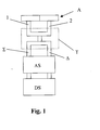
Es ist allgemeiner Stand der Technik, dass in einem zweikanaligen Radarsystem die beiden Subaperturkanäle (1, 2) einer Antenne (A), im Antennenfrontend, mittels eines Hohlleiterteils (T), üblicherweise ein sogenanntes MagicT, zu einem Summen-(Σ) und Differenzkanal (Δ) zusammengefaßt werden können. Eine derartige Anordnung ist in Fig. 1 dargestellt. In Fig. 1 ist darüber hinaus gezeigt, dass der Summen-(Σ) und Differenzkanalsignale (Δ) einer analogen (AS) und digitalen Signalaufbereitung (DS) zugeführt werden.It is general state of the art that in a two-channel radar system two subaperture channels (1, 2) of an antenna (A), in the antenna front, by means of a Waveguide part (T), usually a so-called MagicT, to a sum (Σ) and differential channel (Δ) can be combined. Such an arrangement is shown in Fig. 1. In Fig. 1 is also shown that the sum (Σ) and differential channel signals (Δ) of an analog (AS) and digital signal processing (DS) are fed.
In der digitalen Signalverarbeitung eines SAR- Radars wird das Summenkanalsignal dazu verwendet, sogenannte Radarbodenkarten zu erstellen. In der digitalen Signalverarbeitung eines MIT-Radars wird das Summenkanalsignal dazu verwendet, eine Detektion und Erkennung (Indikation) von bewegten Zielen (moving targets) in Radarbodenkarten ähnlichen Bildern durchzuführen. Fig. 2 zeigt hierzu ein typisches, mit dem MTl-Verfahren erzeugtes Entfernung-Dopplerbild im Summenkanal nach Detektion von Fest- und Bewegtzielen. Dabei sind die Signalleistungen über den Entfernungstoren und der normalisierten Frequenz f/fs aufgetragen. In dem dargestellten Diagramm ist deutlich zu erkennen, dass der Bereich des Antennenleuchtflecks (heller Bereich), auch als Hauptkeulenclutter bezeichnet, aufgrund einer Relativgeometrieänderung während der Beleuchtungszeit, gegenüber der Dopplerfrequenzposition Null verschoben ist. Die in dem Bild dargestellten Kreise bezeichnen die detektierten Fest- und Bewegtziele. In Fig. 2 befindet sich die Dopplerfrequenzposition des Hauptkeulenclutters beispielhaft bei einer normalisierten Frequenz von 0,2.In the digital signal processing of a SAR radar, the sum channel signal is used to create so-called radar bottom maps. In the digital signal processing of an MIT radar, the sum channel signal is used to carry out detection and detection (indication) of moving targets in images similar to radar floor maps. 2 shows a typical distance Doppler image in the summation channel after the detection of fixed and moving targets. The signal powers are plotted over the distance gates and the normalized frequency f / f s . The diagram shows clearly that the area of the antenna light spot (bright area), also referred to as the main lobe clutter, is shifted from the Doppler frequency position to zero due to a change in the relative geometry during the illumination time. The circles shown in the picture indicate the detected fixed and moving targets. In Fig. 2, the Doppler frequency position of the main lobe clutter is exemplarily at a normalized frequency of 0.2.
Während in der SAR- Radarsignalverarbeitung das Differenzkanalsignal nicht weiter verwendet wird, wird in der entsprechenden MIT- Radarsignalverarbeitung das Differenzkanalsignal dazu benötigt, zum Einen eine Trennung von Fest- und Bewegtzielen zu erreichen und zum Anderen eine Repositionierung der, bezüglich der Dopplerfrequenz verschobenen, bewegten Ziele durchzuführen.While in the SAR radar signal processing, the differential channel signal does not continue is used, the difference channel signal is used in the corresponding MIT radar signal processing this requires, on the one hand, a separation of fixed and moving targets to achieve and on the other hand a repositioning, with respect to the Doppler frequency to carry shifted, moving targets.
Ein Verfahren zur Festzielunterdrückung ist z.B. das sogenannte STAP(Space Time
Adaptive Processing) Verfahren. Um eine möglichst hohe Bewegtzielunterdrückung
zu erzielen, ist es notwendig, dass die Subaperturkanalsignale in Amplitude exakt
gleich sind und sich in der Phase nur durch einen, durch die Relativgeometrie und
Antennenanordnung bedingten Phasenwert unterscheiden. Zur Bewegtzielrepositionierung
ist es ebenfalls nötig, unterschiedliche Phasendifferenzen zwischen den
Subaperturkanalsignalen, die zu Fehlpositionierungen führen, zu kompensieren.
Eine übliche Methode zur Bestimmung der Kompensationsfaktoren von Amplitude
und Phase, ist die Benutzung von definierten Testsignalen, die in das Hohlleiterteil
eingespeist, beziehungsweise über die Antenne eingestrahlt werden. Dies geschieht
vor dem eigentlichen Einsatz der Radarantenne. Die Summen- und Differenzkanalsignale
hinter dem Hohlleiterteil werden danach in die Eingangssignale vor dem Hohlleiterteil,
also in die Signale der beiden Subaperturkanäle zurückgerechnet. Sind die
Korrekturfaktoren korrekt bestimmt worden, so sind die beiden Signale identisch. Die
Faktoren werden im Speicher der digitalen Signalverarbeitung abgelegt und während
des Einsatzes der Radarantenne aus diesem ausgelesen. Ein derartiges Verfahren
ist von Shunjun W. et al. in "Adaptive Channel Equalization für Space-Time Adaptive
Processing"; IEEE International Radar Conference 1995 beschrieben worden.One method for suppressing fixed targets is, for example, the so-called STAP (Space Time Adaptive Processing) method. In order to achieve the highest possible suppression of moving targets, it is necessary that the sub-aperture channel signals are exactly the same in amplitude and differ in phase only by a phase value caused by the relative geometry and antenna arrangement. To reposition the moving target, it is also necessary to compensate for different phase differences between the sub-aperture channel signals, which lead to incorrect positioning.
A common method for determining the compensation factors of amplitude and phase is the use of defined test signals which are fed into the waveguide part or are radiated in via the antenna. This happens before the radar antenna is actually used. The sum and difference channel signals behind the waveguide part are then calculated back into the input signals upstream of the waveguide part, that is to say into the signals of the two sub-aperture channels. If the correction factors have been correctly determined, the two signals are identical. The factors are stored in the memory of the digital signal processing and read out from it during use of the radar antenna. Such a method is described by Shunjun W. et al. in "Adaptive Channel Equalization for Space-Time Adaptive Processing"; IEEE International Radar Conference 1995.
Die Berechnung der Signale der Subaperturkanäle erfolgt üblicherweise gemäß folgender
Gleichungen:
Nachteilig hierbei ist, dass diese Vorgehensweise vorab durchgeführt werden muß und dass Amplituden- und Phasengleichlaufunterschiede, die während des laufenden Betriebs auftreten, nicht mehr korrigiert werden können. Nachteilig ist ebenfalls, dass im laufenden Betrieb Testsignale eingespeist werden müssen, was zu einem höheren Aufwand und zu einer möglichen Unterbrechung der kohärenten digitalen Signalverarbeitung führt.The disadvantage here is that this procedure must be carried out in advance and that amplitude and phase tracking differences that occur during the current Operating occur, can no longer be corrected. Another disadvantage is that test signals must be fed in during operation, which leads to a higher Effort and a possible interruption of the coherent digital signal processing leads.
Aufgabe der Erfindung ist es, ein Verfahren anzugeben, mit dem eine gegenüber dem Stand der Technik verbesserte Rückrechnung des Summen- und Differenzkanalsignals auf das am Ausgang der beiden Subaperturen vorliegende Signal möglich ist. Eine weitere Aufgabe der Erfindung besteht darin, ein Verfahren anzugeben, welches ohne ein Testsignal auskommt und während des laufenden Betriebs aus den Radarsignalen zur Bilderzeugung adaptiv die Korrekturfaktoren berechnet und die Korrektur durchführt.The object of the invention is to provide a method with which one opposite the prior art improved back calculation of the sum and difference channel signal to the signal present at the output of the two subapertures is. Another object of the invention is to provide a method which manages without a test signal and during operation from the Radar signals for image generation adaptively calculate the correction factors and the Corrects.
Diese Aufgabe wird mit dem Verfahren gemäß Patentanspruch 1 gelöst. Vorteilhafte
Ausführungen des Verfahrens sind Gegenstand von Unteransprüchen.This object is achieved with the method according to
Erfindungsgemäß werden aus dem amplituden- und phasenverschobenen Summenund
Differenzkanalsignal durch Einsetzen in folgende Gleichungen die Signale der
beiden Subaperturkanäle berechnet:

Mit dem Phasenkorrekturfaktor Φ0 wird dabei die Phasendifferenz zwischen Summen- und Differenzkanal bestimmt.The phase difference between the sum and difference channels is determined with the phase correction factor kanal 0 .
Die Erfindung sowie vorteilhafte Ausführungen der Erfindung werden im weiteren anhand von Diagrammen näher erläutert. Es zeigen:
- Fig. 1
- ein Blockschaltbild mit dem Signalverlauf nach den beiden Subaperturen im Frontend bis zur digitale Signalverarbeitung,
- Fig. 2
- ein beispielhaftes Entfernungs-Dopplerbild im Summenkanal nach der Detektion der Fest/Bewegtziele,
- Fig. 3
- den beispielhaften Verlauf der Phasendifferenz zwischen Summen- und Differenzkanal über der normalisierten Frequenz,
- Fig. 4
- den Verlauf der Phasendifferenz gemäß Fig. 3 in einem Ausschnitt um die Dopplerfrequenzposition des Hauptkeulenclutters, sowie den Verlauf der Phasendifferenz zwischen Summen- und Differenzkanal nach der Phasenkorrektur,
- Fig. 5
- den beispielhaften Verlauf der Signalleistungen der beiden Subaperturkanäle über der normalisierten Frequenz.
- Fig. 1
- a block diagram with the signal curve after the two subapertures in the frontend to digital signal processing,
- Fig. 2
- an exemplary distance Doppler image in the sum channel after the detection of the fixed / moving targets,
- Fig. 3
- the exemplary course of the phase difference between the sum and difference channel over the normalized frequency,
- Fig. 4
- 3 in a section around the Doppler frequency position of the main lobe clutter, and the course of the phase difference between the sum and difference channel after the phase correction,
- Fig. 5
- the exemplary course of the signal powers of the two subaperture channels over the normalized frequency.
Zur Schätzung des Phasenkorrekturfaktors Φ0 werden in einer vorteilhaften Ausführung der Erfindung folgende Berechnungsschritte durchgeführt:
- Berechnung der Dopplerfrequenzposition des Hauptkeulenclutters,
- Korrektur der Summen- und Differenzkanalsignals XS(r, t), XD(r, t), wobei für jedes der verschiedenen Entfernungstore in der Phase eine Verschiebung des Summen- und Differenzkanalsignals als Funktion über der Pulswiederholzeit in die Frequenznulllage erfolgt,
- Filtern der, in die Nullage geschobenen Summen- und Differenzkanalsignale mittels eines Tiefpasses zur Unterdrückung von hochfrequentem Phasenrauschens
- Abtastratenreduktion der Summen- und Differenzkanalsignale zur Reduktion der Rechenleistung und Erhöhung der spektralen Auflösung,
- Transformation des gefilterten Summen- und Differenzkanalsignale XS(r, t), XD(r, t)mittels einer gefensterten Fast-Fourier-Transformation (FFT) in den Dopplerfrequenzbereich,
- Berechnung der Kreuzkorrelation des Summen- und Differenzkanalsignale XS(r, f), XD(r, f) über die verschiedenen Entfernungstore, wobei diese Berechnung für jede Dopplerfrequenzposition erfolgt,
- Ermittlung des Verlaufs der Phasendifferenz zwischen Summen- und Differenzkanal
XS(r, f), XD(r, f) aus den in Schritt 5 berechneten Korrelationen über den in
Schritt 1 adaptiv berechneten Frequenzbereich, - Bestimmung des Phasenkorrekturfaktors Φ0 durch Berechnung des aritmetischen
Mittelwertes der Phasendifferenz zwischen Summen- und Differenzkanal über
den in
Schritt 1 adaptiv berechneten Frequenzbereich des Hauptkeulenclutters.
- Calculation of the Doppler frequency position of the main lobe clutter,
- Correction of the sum and difference channel signals X S (r, t), X D (r, t), the sum and difference channel signals being shifted in phase for each of the various distance gates as a function of the pulse repetition time into the zero frequency position,
- Filtering of the sum and difference channel signals shifted into the zero position by means of a low-pass filter to suppress high-frequency phase noise
- Sampling rate reduction of the sum and difference channel signals to reduce the computing power and increase the spectral resolution,
- Transformation of the filtered sum and difference channel signals X S (r, t), X D (r, t) into the Doppler frequency range by means of a windowed Fast Fourier Transformation (FFT),
- Calculation of the cross correlation of the sum and difference channel signals X S (r, f), X D (r, f) via the various distance gates, this calculation being carried out for each Doppler frequency position,
- Determination of the course of the phase difference between the sum and difference channels X S (r, f), X D (r, f) from the correlations calculated in step 5 over the frequency range adaptively calculated in
step 1, - Determination of the phase correction factor Φ 0 by calculating the arithmetic mean value of the phase difference between the sum and difference channel over the frequency range of the main lobe clutter adaptively calculated in
step 1.
Für die Bestimmung des Phasenkorrekturfaktors Φ0 wird bevorzugt der Bereich der größten Energie im Summen- und Differenzkanal MTI-Bild herangezogen. Dieser Bereich größter Energie ist insbesondere der Bereich der Hauptkeule der Antenne.The area of the greatest energy in the sum and difference channel MTI image is preferably used to determine the phase correction factor Φ 0 . This area of greatest energy is in particular the area of the main lobe of the antenna.
Die Berechnung der Dopplerfrequenzposition des Hauptkeulenclutters im ersten Berechnungsschritt kann dabei mit dem Verfahren in der nicht vorveröffentlichten Patentanmeldung DE 101 24 865.2 erfolgen. Dieser Bereich wird erfindungsgemäß aus den Radardaten adaptiv geschätzt.The calculation of the Doppler frequency position of the main lobe clutter in the first calculation step can use the method in the unpublished patent application DE 101 24 865.2. This area is according to the invention adaptively estimated the radar data.
Die Korrektur der Summen- und Differenzkanalsignale XS(r, t), XD(r, t) im zweiten Berechnungsschritt
wird auch als sogenanntes Deramping-Verfahren bezeichnet. Dabei
wird für jedes der verschiedenen Entfernungstore in der Phase eine Verschiebung
des Summen- und Differenzkanalsignals als Funktion über der Pulswiederholzeit t in
die Frequenznulllage durchgeführt. Dies erfolgt entsprechend folgender Gleichung:
Sobald die Summen- und Differenzkanalsignale in die Frequenznullage geschoben worden sind, werden diese vorteilhaft zur Unterdrückung von hochfrequentem Phasenrauschen tiefpassgefiltert. Dadurch reduziert sich ebenfalls die Bandbreite der Signale. Die Tiefpassfilterung erfolgt im dritten Rechenschritt.As soon as the sum and difference channel signals are pushed into the frequency zero position have been used, these are advantageous for the suppression of high-frequency phase noise low-pass filtered. This also reduces the bandwidth of the Signals. The low pass filtering takes place in the third calculation step.
Die Bandbreitenreduktion wird ausgenutzt um eine Reduktion der Anzahl der Signalwerte, eine sogenannte Abtastratenreduktion, durchzuführen. Somit ergibt sich vorteilhaft eine Reduktion der Rechenzeit bei gleicher spektraler Auflösung, bzw. vorteilhaft eine Erhöhung der spektralen Auflösung bei Erhöhung der Anzahl der reduzierten Signalwerte. Die Abtastratenreduktion wird im vierten Rechenschritt durchgeführt.The bandwidth reduction is used to reduce the number of signal values, a so-called sampling rate reduction. This is advantageous a reduction in computing time with the same spectral resolution, or advantageous an increase in the spectral resolution with an increase in the number of reduced ones Signal values. The sampling rate reduction is carried out in the fourth calculation step.
Innerhalb einer Entfernungszelle befinden sich in den Summen- und Differenzkanalzeitsignalen mehrere Punktziele, die sich hinsichtlich Amplitude und Phase unterscheiden. Diese können aber im Zeitsignal nicht aufgelöst werden. Vorteilhaft wird in einem fünften und sechsten Berechnungsschritt somit eine Transformation der gefilterten Summen- und Differenzkanalsignale in den Spektralbereich, den sogenannten Dopplerfrequenzbereich durchgeführt. Die Transformation erfolgt vorteilhaft mittels einer gefensterten Fourier Fast Transformation (FFT). Hieraus ergibt sich, dass die einzelnen Punktziele hinsichtlich ihrer Frequenz, d.h. der zeitlichen Ableitung der Phase unterschieden werden können.The sum and difference channel time signals are located within a distance cell several point targets that differ in amplitude and phase. However, these cannot be resolved in the time signal. Is advantageous in a fifth and sixth calculation step thus a transformation of the filtered Sum and difference channel signals in the spectral range, the so-called Doppler frequency range carried out. The transformation is advantageously carried out using a windowed Fourier Fast Transformation (FFT). It follows that the individual point targets with regard to their frequency, i.e. the time derivative of the Phase can be distinguished.
Eine FFT kann dabei als eine Anordnung von mehreren Frequenzteilbändern angesehen werden. Jedes Frequenzteilband besitzt dabei eine Sperrdämpfung von ca.14 dB, entsprechend der Impulsantwort eines Rechteckfensters. Das bedeutet, dass Amplituden des Nachbarfrequenzbandes mit einer Dämpfung von ca. 14 dB ebenfalls durchgelassen werden. Werden die Zeitsignale vorteilhaft mittels einer Fensterfunktion hoher Sperrdämpfung gefenstert, so ergibt sich ein nahezu unverfälschtes Spektralsignal in jedem Frequenzband. An FFT can be viewed as an arrangement of several frequency subbands become. Each frequency subband has an attenuation of approx. 14 dB, corresponding to the impulse response of a rectangular window. It means that Amplitudes of the neighboring frequency band with an attenuation of approx. 14 dB also be allowed through. The time signals are advantageous by means of a window function high blocking attenuation, this results in an almost unadulterated spectral signal in every frequency band.
Mittels der gefensterten FFT sind aus den Entfernungs-Zeit-(slow time) Bildern Entfernungs-Dopplerfrequenzbilder
entstanden. Für jede Dopplerfrequenzposition wird in
einem sechste Berechnungsschritt das Summen- und Differenzkanalspektrum als
Funktion über die einzelnen Entfernungstore miteinander kreuzkorreliert. Das bedeutet,
dass die komplexen Vektoren der Signale miteinander multipliziert und aufsummiert
werden. Das Ergebnis ist ein komplexer Wert für jede Dopplerfrequenzposition.
Dieser komplexe Wert besitzt einen Realteil Re und einem Imaginärteil Im. Die
Phase dieses Wertes in der Einheit Grad berechnet sich aus:

Sie wird im Folgenden als Differenzphase bezeichnet.It is referred to below as the difference phase.
Die Berechnung der Phasen für jede Dopplerfrequenzposition ergibt dann in einem siebten Schritt einen Verlauf, der die Phasendifferenz zwischen Summen- und Differenzkanalspektrum angibt. Fig. 3 zeigt einen beispielhaften Verlauf der Phasendifferenz zwischen Summen- und Differenzkanalspektrum im Hauptkeulenclutterbereich, wobei die Dopplerfrequenzposition des Hauptkeulenclutters entsprechend Fig. 2 bei 0,2 liegt. Aus Fig. 3 ergibt sich somit für dieses Beispiel für die mittlere Dopplerfrequenzposition des Hauptkeulenclutters eine Phasendifferenz von -110° zwischen dem Summen- und Differenzkanalspektrum. Diese Phasendifferenz, die abhängig von der Ausführung des MagicT z.B. 90° betragen kann, wird erfindungsgemäß mittels des Phasenkorrekturfaktors Φ0 im Spektrum korrigiert.The calculation of the phases for each Doppler frequency position then gives a course in a seventh step, which indicates the phase difference between the sum and difference channel spectrum. FIG. 3 shows an example of the phase difference between the sum and difference channel spectrum in the main lobe clutter region, the Doppler frequency position of the main lobe clutter according to FIG. 2 being 0.2. For this example, FIG. 3 shows a phase difference of -110 ° between the sum and difference channel spectrum for the mean Doppler frequency position of the main lobe clutter. This phase difference, which can be 90 °, for example, depending on the design of the MagicT, is corrected according to the invention by means of the phase correction factor Φ 0 in the spectrum.
Zur Bestimmung des Phasenkorrekturfaktors Φ0 wird dann im achten Berechnungsschritt innerhalb des, im ersten Berechnungsschritts ermittelten, Dopplerfrequenzpositionsbereichs des Hauptkeulenclutters der arithmetische Mittelwert der Differenzphasenwerte berechnet. Dieser Mittelwert entspricht dem Phasenkorrekturfaktor Φ0. Fig. 4 zeigt einen vergrößerten Ausschnitt um die Dopplerfrequenzposition des Hauptkeulenclutters aus Fig. 3. Außerdem ist eine weitere Kurve eingezeichnet, welche dem, um den Phasenkorrekturfaktor a0 korrigierten Verlauf der Phasendifferenz zwischen Summen- und Differenzkanalspektrum entspricht. Diese korrigierte Kurve weist bei der Dopplerfrequenzposition des Hauptkeulenclutters eine Phasendifferenz von 0° zwischen dem Summen- und Differenzkanalspektrum auf.To determine the phase correction factor Φ 0 , the arithmetic mean of the difference phase values is then calculated in the eighth calculation step within the Doppler frequency position range of the main lobe clutter determined in the first calculation step. This mean corresponds to the phase correction factor Φ 0 . FIG. 4 shows an enlarged section around the Doppler frequency position of the main lobe clutter from FIG. 3. In addition, a further curve is drawn in, which corresponds to the course of the phase difference between the sum and difference channel spectrum corrected by the phase correction factor a 0 . This corrected curve has a phase difference of 0 ° between the sum and difference channel spectrum at the Doppler frequency position of the main lobe clutter.
In einer weiteren vorteilhaften Ausführung der Erfindung wird der Amplitudenkorrekturfaktor a0 mittels folgender Berechnungsschritte geschätzt:
- Berechnung der Spektren für die beiden Subaperturkanäle gemäß Gleichungen (1) und (2) mit a0=1,
- Berechnung je eines mittleren Leistungsdichtespektrums für den einen und den anderen Subaperturkanal durch geometrische Mittelung der mit Gleichung (1) und (2) berechneten Subaperturkanalspektren über verschiedene Entfernungstore,
- Berechnung der Differenz der Leistungsdichtespektren zwischen den, über verschiedene Entfernungstore gemittelten Subaperturkanalleistungsdichtespektren,
- Bestimmung des Amplitudenkorrekturfaktors a0 durch Berechnung des arithmetischen
Mittelwertes der Differenz über den in
Schritt 1 der Phasenkorrekturberechnung adaptiv berechneten Frequenzbereich des Hauptkeulenclutters.
- Calculation of the spectra for the two subaperture channels according to equations (1) and (2) with a 0 = 1,
- Calculation of an average power density spectrum for one and the other subaperture channel by geometric averaging of the subaperture channel spectra calculated using equations (1) and (2) over different distance gates,
- Calculation of the difference in the power density spectra between the sub-aperture channel power density spectra averaged over different distance gates,
- Determination of the amplitude correction factor a 0 by calculating the arithmetic mean value of the difference over the frequency range of the main lobe clutter adaptively calculated in
step 1 of the phase correction calculation.
Im ersten Berechnungsschritt werden mittels des geschätzten Phasenkorrekturfaktors Φ0 die Frequenzspektren für die beiden Subaperturkanäle gemäß den Gleichungen (1) und (2) bestimmt, wobei der Amplitudenkorrekturfaktor a0 auf 1 gesetzt wird. Im zweiten und dritten Berechnungsschritt werden aus den komplexen Frequenzspektren die Leistungsdichtespektren berechnet und diese vorteilhaft über eine vorgebbare Auswahl von Entfernungstoren geometrisch gemittelt, d.h. der Mittelwert der logarithmierten Leistungen berechnet.In the first calculation step, the frequency spectra for the two subaperture channels are determined according to equations (1) and (2) by means of the estimated phase correction factor wobei 0, the amplitude correction factor a 0 being set to 1. In the second and third calculation steps, the power density spectra are calculated from the complex frequency spectra and these are advantageously geometrically averaged over a predeterminable selection of distance gates, ie the mean value of the logarithmic powers is calculated.
In Fig. 5 ist ein beispielhafter Verlauf der Leistungsdichtespektren der beiden Subaperturkanäle
(Kanal 1 und Kanal 2) über der normalisierten Frequenz f/fs dargestellt.
Da im ersten Berechnungsschritt der Amplitudenkorrekturfaktor a0=1 beträgt, weichen
die Kurvenverläufe der beiden Leistungsdichtespektren voneinander ab.5 shows an exemplary course of the power density spectra of the two sub-aperture channels (
In einem vierten Berechnungsschritt wird der geometrische Mittelwert der Differenz der gemittelten Leistungsdichtespektren innerhalb des Dopplerfrequenzpositionsbereichs des Hauptkeulenclutters bestimmt. In a fourth calculation step, the geometric mean of the difference the average power density spectra within the Doppler frequency position range of the main lobe clutters.
Der in dem zweiten, dritten und vierten Berechnungsschritt geschätzte Amplitudenkorrekturfaktor a0 gibt somit an, um wieviel die Leistungsdichtespektren der beiden Subaperturkanalspektren zumindest im Bereich des Hauptkeulenclutters konstant voneinander abweichen.The amplitude correction factor a 0 estimated in the second, third and fourth calculation step thus indicates by how much the power density spectra of the two sub-aperture channel spectra constantly deviate from one another, at least in the region of the main lobe clutter.
In einer weiteren vorteilhaften Ausführung der Erfindung erfolgt die Stabilisierung der Schätzung der konstanten Phasen- und Amplitudenkorrekturfaktoren rekursiv von Signalpulspaket zu Signalpulspaket. Dabei wird eine Häufigkeitsverteilung der Schätzwerte berechnet und der Wert mit der größten Häufigkeit als Schätzwert weiterverwendet.In a further advantageous embodiment of the invention, the stabilization of the Estimation of the constant phase and amplitude correction factors recursively from Signal pulse package to signal pulse package. A frequency distribution of the Estimates are calculated and the value with the greatest frequency is used as an estimate.
Ein Vorteil der Erfindung ist, dass der Summen- und Differenzkanal mittels digitaler Signalverarbeitung in die Einzelkanäle der Subapertur zurückgerechnet werden kann, ohne dass Veränderungen an der Antenne (Frontend) vorgenommen werden müssen. Diese Berechnungen erfolgen während des gewöhnlichen Betriebs der Antenne, ohne dass die kohärente Signalverarbeitung unterbrochen werden muß. Ein wesentlicher Vorteil der Erfindung ist, dass kein Testsignal zur Berechnung benötigt wird, sondern dies auf den Radardaten selbst geschieht. Außerdem liefert das erfindungsgemäße Verfahren auch bei einem schlechtem Signal/Rauschverhältnis sehr gute Ergebnisse.An advantage of the invention is that the sum and difference channel by means of digital Signal processing can be calculated back into the individual channels of the subaperture, without having to make any changes to the antenna (front end). These calculations are done during normal antenna operation, without having to interrupt the coherent signal processing. An essential one The advantage of the invention is that no test signal is required for the calculation, but this happens on the radar data itself. In addition, the invention provides Very good procedure even with a bad signal / noise ratio Results.
Ein weiterer Vorteil ist, dass für das erfindungsgemäße Verfahren keine Kenntnis der Gleichlaufeigenschaften der Kanäle benötigt wird. Sofern die Gleichlaufunterschiede der Kanäle zeitabhängig sind, wird dies durch die Adaptivität des erfindungsgemäßen Verfahrens berücksichtigt, indem das Verfahren in jedem n-ten Rechenschritt angewendet wird und die Schätzwerte mit der größten Wahrscheinlichkeit verwendet werden.Another advantage is that for the method according to the invention no knowledge of the Synchronous properties of the channels is required. If the synchronization differences of the channels are time-dependent, this is due to the adaptivity of the invention Method taken into account by applying the method in every nth calculation step and the estimates are used with the greatest probability.
Das erfindungsgemäße Verfahren läßt sich auch auf andere Signale außer Radarsignale übertragen.The method according to the invention can also be applied to signals other than radar signals transfer.
Claims (4)

Applications Claiming Priority (2)
| Application Number | Priority Date | Filing Date | Title |
|---|---|---|---|
| DE10146643A DE10146643C1 (en) | 2001-09-21 | 2001-09-21 | Procedure for calibrating the radar signals at the subapertures of the antenna of a two-channel SAR / MTI radar system |
| DE10146643 | 2001-09-21 |
Publications (3)
| Publication Number | Publication Date |
|---|---|
| EP1296157A2 true EP1296157A2 (en) | 2003-03-26 |
| EP1296157A3 EP1296157A3 (en) | 2003-07-30 |
| EP1296157B1 EP1296157B1 (en) | 2006-05-31 |
Family
ID=7699850
Family Applications (1)
| Application Number | Title | Priority Date | Filing Date |
|---|---|---|---|
| EP02016541A Expired - Lifetime EP1296157B1 (en) | 2001-09-21 | 2002-07-24 | Method for calibrating radar signals from the sub-apertures of the antenna of a two-channel SAR/MTI radar system |
Country Status (3)
| Country | Link |
|---|---|
| US (1) | US6686874B2 (en) |
| EP (1) | EP1296157B1 (en) |
| DE (2) | DE10146643C1 (en) |
Cited By (7)
| Publication number | Priority date | Publication date | Assignee | Title |
|---|---|---|---|---|
| CN100526912C (en) * | 2006-06-02 | 2009-08-12 | 中国科学院电子学研究所 | Active externally coefficient potentiometer and scaling method of wideband synthetic aperture radar |
| CN101236247B (en) * | 2008-03-07 | 2010-06-16 | 北京航空航天大学 | Star-carrying multichannel antenna SAR data channel amplitude and phase error correction platform |
| CN101082666B (en) * | 2006-06-02 | 2011-07-27 | 中国科学院电子学研究所 | Method for realizing high precision modulating radar pulse signal based on automatic test system |
| CN103176172A (en) * | 2013-02-06 | 2013-06-26 | 中国科学院电子学研究所 | Phase measurement compensation method for airborne interferometric SAR (synthetic aperture radar) based on synchronous internal calibration signals |
| CN111352101A (en) * | 2018-12-20 | 2020-06-30 | 中国人民解放军空军预警学院 | Space-time two-dimensional digital difference channel forming method for phased array airborne radar |
| CN112068086A (en) * | 2020-10-17 | 2020-12-11 | 中国电波传播研究所(中国电子科技集团公司第二十二研究所) | Shore-based multi-channel radar amplitude-phase correction method based on external calibration test data |
| CN112698320A (en) * | 2020-12-07 | 2021-04-23 | 南京工业职业技术大学 | Optimization design method of moving target detection filter bank |
Families Citing this family (15)
| Publication number | Priority date | Publication date | Assignee | Title |
|---|---|---|---|---|
| US20030065296A1 (en) * | 2001-02-26 | 2003-04-03 | Kaiser Thomas A. | Absorbent material of water absorbent polymer, thermoplastic polymer, and water and method for making same |
| US6879279B2 (en) * | 2003-01-14 | 2005-04-12 | The Regents Of The University Of California | Differential optical synthetic aperture radar |
| ATE408849T1 (en) * | 2004-11-26 | 2008-10-15 | Saab Ab | ANTENNA BACKLOB ATTENUATION |
| PE20061324A1 (en) | 2005-04-29 | 2007-01-15 | Centocor Inc | ANTI-IL-6 ANTIBODIES, COMPOSITIONS, METHODS AND USES |
| US20090278732A1 (en) * | 2006-04-28 | 2009-11-12 | Paul Antonik | Method and apparatus for simultaneous synthetic aperture radar and moving target indication |
| US7646326B2 (en) * | 2006-04-28 | 2010-01-12 | The United States Of America As Represented By The Secretary Of The Air Force | Method and apparatus for simultaneous synthetic aperture radar and moving target indication |
| CN101950016A (en) * | 2010-09-30 | 2011-01-19 | 重庆长安汽车股份有限公司 | Automotive reversing radar system durability tester |
| CN103885053B (en) * | 2014-03-27 | 2016-07-06 | 中国电子科技集团公司第二十八研究所 | A kind of radar data moving-target based on tracking filter detects processing method |
| CN113287036B (en) * | 2019-09-30 | 2022-09-09 | 华为技术有限公司 | Speed ambiguity resolution method and echo signal processing device |
| CN111123221B (en) * | 2019-12-12 | 2021-11-23 | 上海卫星工程研究所 | Active phased array system SAR channel full link amplitude and phase stability test method |
| JP7351794B2 (en) | 2020-05-19 | 2023-09-27 | 三菱電機株式会社 | Synthetic aperture radar system |
| CN111638494B (en) * | 2020-05-31 | 2022-09-02 | 西南电子技术研究所(中国电子科技集团公司第十研究所) | Multi-channel amplitude and phase correction method for digital beam synthesis system |
| CN113419240B (en) * | 2021-04-26 | 2023-05-16 | 中国科学院空天信息创新研究院 | Moving target detection method based on dual-channel SAR, dual-channel SAR and storage medium |
| CN113295287B (en) * | 2021-05-26 | 2022-11-11 | 中国科学院光电技术研究所 | Hartmann subaperture threshold value reduction method for pupil dynamic intensity distribution |
| CN114442080B (en) * | 2022-01-29 | 2023-10-20 | 南京隼眼电子科技有限公司 | Moving object speed deblurring method and device, electronic equipment and storage medium |
Citations (1)
| Publication number | Priority date | Publication date | Assignee | Title |
|---|---|---|---|---|
| US6144333A (en) * | 1999-08-13 | 2000-11-07 | Raytheon Company | Method for estimating gain and phase imbalance using self-calibrating monopulse angle discriminants in a monopulse radar system |
Family Cites Families (7)
| Publication number | Priority date | Publication date | Assignee | Title |
|---|---|---|---|---|
| US3794998A (en) * | 1972-04-26 | 1974-02-26 | Raytheon Co | Monopulse radar receiver with error correction |
| US4005421A (en) * | 1973-05-30 | 1977-01-25 | Westinghouse Electric Corporation | Monopulse radar system and method for improved low elevation tracking |
| US4368468A (en) * | 1980-12-22 | 1983-01-11 | Westinghouse Electric Corp. | Monopulse radio receiver compensation apparatus |
| US5245347A (en) * | 1980-12-29 | 1993-09-14 | Raytheon Company | All weather tactical strike system (AWTSS) and method of operation |
| FR2595144B1 (en) * | 1986-02-28 | 1988-05-13 | Thomson Csf | SUM AND DIFFERENCE SIGNAL PROCESSING OF A MONOPULSE-TYPE RADAR, WITH A VIEW TO ESTIMATING THE INTERFERENCE PHASE INTRODUCED BETWEEN THESE SIGNALS BY THE SUM AND DIFFERENCE PATHWAY HYPERFREQUENCY CIRCUITS |
| US5051752A (en) * | 1990-11-05 | 1991-09-24 | Hughes Aircraft Company | Angle measurement compensation technique for amplitude comparison monopulse receiver |
| US6124824A (en) * | 1999-01-29 | 2000-09-26 | Cwill Telecommunications, Inc. | Adaptive antenna array system calibration |
-
2001
- 2001-09-21 DE DE10146643A patent/DE10146643C1/en not_active Expired - Fee Related
-
2002
- 2002-07-24 DE DE50206976T patent/DE50206976D1/en not_active Expired - Lifetime
- 2002-07-24 EP EP02016541A patent/EP1296157B1/en not_active Expired - Lifetime
- 2002-09-23 US US10/252,005 patent/US6686874B2/en not_active Expired - Fee Related
Patent Citations (1)
| Publication number | Priority date | Publication date | Assignee | Title |
|---|---|---|---|---|
| US6144333A (en) * | 1999-08-13 | 2000-11-07 | Raytheon Company | Method for estimating gain and phase imbalance using self-calibrating monopulse angle discriminants in a monopulse radar system |
Non-Patent Citations (1)
| Title |
|---|
| SHUNJUN WU ET AL: "Adaptive channel equalization for space-time adaptive processing" RECORD OF THE IEEE 1995 INTERNATIONAL RADAR CONFERENCE (CAT. NO.95CH-3571-0), PROCEEDINGS INTERNATIONAL RADAR CONFERENCE, ALEXANDRIA, VA, USA, 8-11 MAY 1995, Seiten 624-628, XP001157585 1995, New York, NY, USA, IEEE, USA ISBN: 0-7803-2121-9 * |
Cited By (10)
| Publication number | Priority date | Publication date | Assignee | Title |
|---|---|---|---|---|
| CN100526912C (en) * | 2006-06-02 | 2009-08-12 | 中国科学院电子学研究所 | Active externally coefficient potentiometer and scaling method of wideband synthetic aperture radar |
| CN101082666B (en) * | 2006-06-02 | 2011-07-27 | 中国科学院电子学研究所 | Method for realizing high precision modulating radar pulse signal based on automatic test system |
| CN101236247B (en) * | 2008-03-07 | 2010-06-16 | 北京航空航天大学 | Star-carrying multichannel antenna SAR data channel amplitude and phase error correction platform |
| CN103176172A (en) * | 2013-02-06 | 2013-06-26 | 中国科学院电子学研究所 | Phase measurement compensation method for airborne interferometric SAR (synthetic aperture radar) based on synchronous internal calibration signals |
| CN111352101A (en) * | 2018-12-20 | 2020-06-30 | 中国人民解放军空军预警学院 | Space-time two-dimensional digital difference channel forming method for phased array airborne radar |
| CN111352101B (en) * | 2018-12-20 | 2023-08-18 | 中国人民解放军空军预警学院 | Space-time two-dimensional digital difference channel forming method for phased array airborne radar |
| CN112068086A (en) * | 2020-10-17 | 2020-12-11 | 中国电波传播研究所(中国电子科技集团公司第二十二研究所) | Shore-based multi-channel radar amplitude-phase correction method based on external calibration test data |
| CN112068086B (en) * | 2020-10-17 | 2022-03-01 | 中国电波传播研究所(中国电子科技集团公司第二十二研究所) | Shore-based multi-channel radar amplitude-phase correction method based on external calibration test data |
| CN112698320A (en) * | 2020-12-07 | 2021-04-23 | 南京工业职业技术大学 | Optimization design method of moving target detection filter bank |
| CN112698320B (en) * | 2020-12-07 | 2023-10-24 | 南京工业职业技术大学 | Optimal design method of moving target detection filter bank |
Also Published As
| Publication number | Publication date |
|---|---|
| US20030058159A1 (en) | 2003-03-27 |
| DE10146643C1 (en) | 2003-08-14 |
| EP1296157B1 (en) | 2006-05-31 |
| EP1296157A3 (en) | 2003-07-30 |
| DE50206976D1 (en) | 2006-07-06 |
| US6686874B2 (en) | 2004-02-03 |
Similar Documents
| Publication | Publication Date | Title |
|---|---|---|
| EP1296157B1 (en) | Method for calibrating radar signals from the sub-apertures of the antenna of a two-channel SAR/MTI radar system | |
| DE102018102816B3 (en) | RADAR WITH PHASE CORRECTION | |
| DE102018132745B4 (en) | FMCW RADAR WITH INTERFERENCE REJECTION IN THE TIME DOMAIN | |
| EP0795762B1 (en) | Method for azimuth scaling for SAR-data and high precision processor for two-dimensional processing of scan-SAR data | |
| DE102012021010B4 (en) | Synthetic aperture radar for simultaneous image acquisition and moving target detection | |
| DE19757309C1 (en) | Process for processing Spotlight SAR raw data | |
| DE19822957C1 (en) | Method for the detection and suppression of interference signals in SAR data and device for carrying out the method | |
| DE102018123383A1 (en) | Radar detection with interference suppression | |
| EP0533220B1 (en) | Target distinction method, especially for HPRF Doppler radar | |
| DE69214257T2 (en) | Improved ISAR imaging radar system | |
| DE4122592C1 (en) | ||
| EP3385750A1 (en) | Method and device for processing raw sar data | |
| DE102017207604B4 (en) | Radar system with frequency modulation monitoring of a series of similar transmission signals | |
| EP0492132B1 (en) | Method for digitally generating SAR-images and apparatus for carrying out the method | |
| EP4196818B1 (en) | Method and device for determining frequency disturbances in a received signal of an active multi-channel sar system | |
| DE2752338C2 (en) | Radar receiver | |
| DE102006007025A1 (en) | Device for detecting a signal type | |
| DE3520398C2 (en) | ||
| EP1184680B1 (en) | Method for repositioning of moving targets in SAR-images | |
| EP1286415B1 (en) | Method for suppressing jammer signals | |
| EP1034630A1 (en) | Method and measuring device to measure the characteristics of radio channels | |
| EP1134592A1 (en) | Real time STAP filter for fixed target cancellation | |
| DE102018221285A1 (en) | Interference suppression and signal recovery methods | |
| DE4117849C2 (en) | Method for generating a reference function for pulse compression of frequency, phase and / or amplitude modulated signals | |
| EP4139706A1 (en) | Radar method and radar system for a phase-coherent analysis |
Legal Events
| Date | Code | Title | Description |
|---|---|---|---|
| PUAI | Public reference made under article 153(3) epc to a published international application that has entered the european phase |
Free format text: ORIGINAL CODE: 0009012 |
|
| AK | Designated contracting states |
Kind code of ref document: A2 Designated state(s): AT BE BG CH CY CZ DE DK EE ES FI FR GB GR IE IT LI LU MC NL PT SE SK TR |
|
| AX | Request for extension of the european patent |
Extension state: AL LT LV MK RO SI |
|
| PUAL | Search report despatched |
Free format text: ORIGINAL CODE: 0009013 |
|
| AK | Designated contracting states |
Designated state(s): AT BE BG CH CY CZ DE DK EE ES FI FR GB GR IE IT LI LU MC NL PT SE SK TR |
|
| AX | Request for extension of the european patent |
Extension state: AL LT LV MK RO SI |
|
| 17P | Request for examination filed |
Effective date: 20040122 |
|
| AKX | Designation fees paid |
Designated state(s): DE FR GB IT |
|
| 17Q | First examination report despatched |
Effective date: 20050426 |
|
| GRAP | Despatch of communication of intention to grant a patent |
Free format text: ORIGINAL CODE: EPIDOSNIGR1 |
|
| GRAS | Grant fee paid |
Free format text: ORIGINAL CODE: EPIDOSNIGR3 |
|
| GRAA | (expected) grant |
Free format text: ORIGINAL CODE: 0009210 |
|
| AK | Designated contracting states |
Kind code of ref document: B1 Designated state(s): DE FR GB IT |
|
| REG | Reference to a national code |
Ref country code: GB Ref legal event code: FG4D Free format text: NOT ENGLISH |
|
| REF | Corresponds to: |
Ref document number: 50206976 Country of ref document: DE Date of ref document: 20060706 Kind code of ref document: P |
|
| GBT | Gb: translation of ep patent filed (gb section 77(6)(a)/1977) |
Effective date: 20060920 |
|
| ET | Fr: translation filed | ||
| PLBE | No opposition filed within time limit |
Free format text: ORIGINAL CODE: 0009261 |
|
| STAA | Information on the status of an ep patent application or granted ep patent |
Free format text: STATUS: NO OPPOSITION FILED WITHIN TIME LIMIT |
|
| 26N | No opposition filed |
Effective date: 20070301 |
|
| PGFP | Annual fee paid to national office [announced via postgrant information from national office to epo] |
Ref country code: FR Payment date: 20110729 Year of fee payment: 10 |
|
| PGFP | Annual fee paid to national office [announced via postgrant information from national office to epo] |
Ref country code: GB Payment date: 20110721 Year of fee payment: 10 Ref country code: DE Payment date: 20110722 Year of fee payment: 10 |
|
| PGFP | Annual fee paid to national office [announced via postgrant information from national office to epo] |
Ref country code: IT Payment date: 20110725 Year of fee payment: 10 |
|
| GBPC | Gb: european patent ceased through non-payment of renewal fee |
Effective date: 20120724 |
|
| REG | Reference to a national code |
Ref country code: FR Ref legal event code: ST Effective date: 20130329 |
|
| PG25 | Lapsed in a contracting state [announced via postgrant information from national office to epo] |
Ref country code: FR Free format text: LAPSE BECAUSE OF NON-PAYMENT OF DUE FEES Effective date: 20120731 Ref country code: GB Free format text: LAPSE BECAUSE OF NON-PAYMENT OF DUE FEES Effective date: 20120724 Ref country code: DE Free format text: LAPSE BECAUSE OF NON-PAYMENT OF DUE FEES Effective date: 20130201 |
|
| PG25 | Lapsed in a contracting state [announced via postgrant information from national office to epo] |
Ref country code: IT Free format text: LAPSE BECAUSE OF NON-PAYMENT OF DUE FEES Effective date: 20120724 |
|
| REG | Reference to a national code |
Ref country code: DE Ref legal event code: R119 Ref document number: 50206976 Country of ref document: DE Effective date: 20130201 |