EP1134592A1 - Real time STAP filter for fixed target cancellation - Google Patents
Real time STAP filter for fixed target cancellation Download PDFInfo
- Publication number
- EP1134592A1 EP1134592A1 EP01105998A EP01105998A EP1134592A1 EP 1134592 A1 EP1134592 A1 EP 1134592A1 EP 01105998 A EP01105998 A EP 01105998A EP 01105998 A EP01105998 A EP 01105998A EP 1134592 A1 EP1134592 A1 EP 1134592A1
- Authority
- EP
- European Patent Office
- Prior art keywords
- filtering
- correlation
- clutter
- raw data
- phase difference
- Prior art date
- Legal status (The legal status is an assumption and is not a legal conclusion. Google has not performed a legal analysis and makes no representation as to the accuracy of the status listed.)
- Granted
Links
Images
Classifications
-
- G—PHYSICS
- G01—MEASURING; TESTING
- G01S—RADIO DIRECTION-FINDING; RADIO NAVIGATION; DETERMINING DISTANCE OR VELOCITY BY USE OF RADIO WAVES; LOCATING OR PRESENCE-DETECTING BY USE OF THE REFLECTION OR RERADIATION OF RADIO WAVES; ANALOGOUS ARRANGEMENTS USING OTHER WAVES
- G01S13/00—Systems using the reflection or reradiation of radio waves, e.g. radar systems; Analogous systems using reflection or reradiation of waves whose nature or wavelength is irrelevant or unspecified
- G01S13/02—Systems using reflection of radio waves, e.g. primary radar systems; Analogous systems
- G01S13/50—Systems of measurement based on relative movement of target
- G01S13/52—Discriminating between fixed and moving objects or between objects moving at different speeds
- G01S13/522—Discriminating between fixed and moving objects or between objects moving at different speeds using transmissions of interrupted pulse modulated waves
- G01S13/524—Discriminating between fixed and moving objects or between objects moving at different speeds using transmissions of interrupted pulse modulated waves based upon the phase or frequency shift resulting from movement of objects, with reference to the transmitted signals, e.g. coherent MTi
- G01S13/5244—Adaptive clutter cancellation
-
- G—PHYSICS
- G01—MEASURING; TESTING
- G01S—RADIO DIRECTION-FINDING; RADIO NAVIGATION; DETERMINING DISTANCE OR VELOCITY BY USE OF RADIO WAVES; LOCATING OR PRESENCE-DETECTING BY USE OF THE REFLECTION OR RERADIATION OF RADIO WAVES; ANALOGOUS ARRANGEMENTS USING OTHER WAVES
- G01S13/00—Systems using the reflection or reradiation of radio waves, e.g. radar systems; Analogous systems using reflection or reradiation of waves whose nature or wavelength is irrelevant or unspecified
- G01S13/02—Systems using reflection of radio waves, e.g. primary radar systems; Analogous systems
- G01S13/06—Systems determining position data of a target
- G01S13/42—Simultaneous measurement of distance and other co-ordinates
- G01S13/44—Monopulse radar, i.e. simultaneous lobing
- G01S13/449—Combined with MTI or Doppler processing circuits
-
- G—PHYSICS
- G01—MEASURING; TESTING
- G01S—RADIO DIRECTION-FINDING; RADIO NAVIGATION; DETERMINING DISTANCE OR VELOCITY BY USE OF RADIO WAVES; LOCATING OR PRESENCE-DETECTING BY USE OF THE REFLECTION OR RERADIATION OF RADIO WAVES; ANALOGOUS ARRANGEMENTS USING OTHER WAVES
- G01S13/00—Systems using the reflection or reradiation of radio waves, e.g. radar systems; Analogous systems using reflection or reradiation of waves whose nature or wavelength is irrelevant or unspecified
- G01S13/02—Systems using reflection of radio waves, e.g. primary radar systems; Analogous systems
- G01S13/06—Systems determining position data of a target
- G01S13/42—Simultaneous measurement of distance and other co-ordinates
- G01S13/44—Monopulse radar, i.e. simultaneous lobing
- G01S13/4454—Monopulse radar, i.e. simultaneous lobing phase comparisons monopulse, i.e. comparing the echo signals received by an interferometric antenna arrangement
-
- G—PHYSICS
- G01—MEASURING; TESTING
- G01S—RADIO DIRECTION-FINDING; RADIO NAVIGATION; DETERMINING DISTANCE OR VELOCITY BY USE OF RADIO WAVES; LOCATING OR PRESENCE-DETECTING BY USE OF THE REFLECTION OR RERADIATION OF RADIO WAVES; ANALOGOUS ARRANGEMENTS USING OTHER WAVES
- G01S13/00—Systems using the reflection or reradiation of radio waves, e.g. radar systems; Analogous systems using reflection or reradiation of waves whose nature or wavelength is irrelevant or unspecified
- G01S13/02—Systems using reflection of radio waves, e.g. primary radar systems; Analogous systems
- G01S13/50—Systems of measurement based on relative movement of target
- G01S13/52—Discriminating between fixed and moving objects or between objects moving at different speeds
- G01S13/522—Discriminating between fixed and moving objects or between objects moving at different speeds using transmissions of interrupted pulse modulated waves
- G01S13/524—Discriminating between fixed and moving objects or between objects moving at different speeds using transmissions of interrupted pulse modulated waves based upon the phase or frequency shift resulting from movement of objects, with reference to the transmitted signals, e.g. coherent MTi
- G01S13/5242—Discriminating between fixed and moving objects or between objects moving at different speeds using transmissions of interrupted pulse modulated waves based upon the phase or frequency shift resulting from movement of objects, with reference to the transmitted signals, e.g. coherent MTi with means for platform motion or scan motion compensation, e.g. airborne MTI
Definitions
- the invention relates to a method for calculating the coefficients of a STAP filter and for filtering radar raw data of the range Doppler matrices of two Adjacent reception channels using Space-Time Adaptive Processing STAP.
- Radar raw data consist of a mixture of signals (e.g. echoes from moving ones and fixed goals) and interference (e.g. noise).
- signals e.g. echoes from moving ones and fixed goals
- interference e.g. noise
- STAP space-time adaptive processing
- the object of the invention is, in the context of STAP processing, the filter coefficients and the filtering of the radar raw data of the range Doppler matrices X left and X To calculate and perform two reception channels on the right in a simple manner, so that this STAP filter can be used in real-time systems.
- the theoretical basis for the method according to the invention is the fact that with typical raw SAR data in the signal spectrum of two adjacent channels Doppler frequency and the phase difference are correlated.
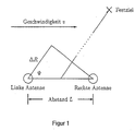
- Figure 1 shows the geometric relationships between two adjacent antennas ('left' channel and 'right' channel) as well as a fixed destination.
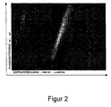
- Figure 2 shows an example of the correlation of the signal spectra of two adjacent channels regarding the Doppler frequency and the phase difference.
- v is the speed of the radar antennas
- ⁇ the wavelength of the radar signal
- ⁇ the azimuth angle at which a target is seen, whereby the target itself does not move.
- Equation 4 only applies to the area of Main antenna lobe applies.
- the calculation of the filter coefficients and the filtering of the radar raw data in the frequency domain can be divided into three steps.
- a first step weighted averages are used ⁇ ( l ) the phase differences ⁇ ( k , l ) across all distance gates k X left and X determined on the right .
- n azimuth cells 1 It is important to make a suitable selection of n azimuth cells 1 , which is to be made dependent on the width of the main antenna lobe.
- the selection of suitable azimuth cells 1 is advantageously designed such that the selected area is limited to the area for which the linear relationship between Doppler frequency and phase difference, as shown in FIG. 2, applies.
- This area is characterized in that the amount of the cross-correlation of the Antenna characteristic is greater than or equal to a suitable threshold.
- the power P ( k , l ) of the radar raw data is used in a suitable manner for weighting the values of ⁇ ( k , l ).
- the power P ( k , l ) can be used to weight ⁇ , ( k , l ) in such a way that for each of the N selected columns of X left and X on the right the cross correlation is calculated and the sum over all correlation values when the phase difference is calculated ⁇ ( l ) is used.
- the values of are determined by suitable addition or subtraction of a constant to be determined ⁇ ( l ) keep in the range of - ⁇ and + ⁇ . This constant is to be determined in such a way that the function of the phase differences ⁇ ⁇ ( l ) increases monotonically in the range of - ⁇ and + ⁇ .
- the parameters of a regression line are determined, which approximately describe the correlation between Doppler frequency and phase difference. This is done by evaluating the functional relationship of ⁇ ( l ) reached.
- Linear regression for example, can be used as a method for estimating the parameters of the regression line, in which the sum of all squares of errors is minimized. The result is the two parameters of the regression line slope m and offset b , which are considered in the subsequent method step as the variables describing the correlation between phase difference and Doppler frequency.
- the first case relates to the n azimuth cells or regions 1 , which were selected in relation to the width of the main lobe in the first method step.
- the phase rotations of the radar raw data in X right over those in X corrected left and to form Y clutter-free according to equation 5: Y clutter-free ( k , l ) X Left ( k, l ) - X right ( k, l ) ⁇ e - j ( m ⁇ l + b )
- the second case relates to all other azimuth cells or regions 1 .
- the two matrices X left and X right just added coherently according to equation 6:
- Y clutter-free ( k, l ) X Left ( k, l ) + X right ( k, l )
- the use of the invention shows Procedure that moving targets within the main antenna lobe, but their echoes appear outside the main antenna lobe, are coherently amplified. Moving goals In the middle of the main antenna lobe there is up to 6dB in intensity raised.
Landscapes
- Engineering & Computer Science (AREA)
- Radar, Positioning & Navigation (AREA)
- Remote Sensing (AREA)
- Computer Networks & Wireless Communication (AREA)
- Physics & Mathematics (AREA)
- General Physics & Mathematics (AREA)
- Radar Systems Or Details Thereof (AREA)
- Radiation-Therapy Devices (AREA)
- Apparatus For Radiation Diagnosis (AREA)
- Picture Signal Circuits (AREA)
- Measurement Of Velocity Or Position Using Acoustic Or Ultrasonic Waves (AREA)
Abstract
Description
Die Erfindung betrifft ein Verfahren zur Berechnung der Koeffizienten eines STAP-Filters und zur Filterung von Radar-Rohdaten der Entfernungs-Doppler-Matrizen zweier benachbarter Empfangskanäle mittels Space-Time Adaptive Processing STAP.The invention relates to a method for calculating the coefficients of a STAP filter and for filtering radar raw data of the range Doppler matrices of two Adjacent reception channels using Space-Time Adaptive Processing STAP.
Radar-Rohdaten bestehen aus einer Mischung von Signalen (z.B.: Echos von bewegten und feststehenden Zielen) und Störungen (z.B.: Rauschen). In der Regel sollen bei der Auswertung dieser Radar-Rohdaten die Störungen unterdrückt werden, so daß die Signale gut detektierbar sind.Radar raw data consist of a mixture of signals (e.g. echoes from moving ones and fixed goals) and interference (e.g. noise). As a rule, at Evaluation of this radar raw data, the interference can be suppressed, so that the Signals are easy to detect.
Zur Verbesserung der Detektion von bewegten Zielen zum Beispiel in SAR-Bildern ist es notwendig Störungen als auch Signale, welche von feststehenden Zielen stammen, zu unterdrücken. Ein geeignetes Verfahren hierfür ist das Space-Time-Adaptive-Processing (STAP). Bei den hierzu bekannten Verfahren werden die Radar-Rohdaten in der Regel im Zeitbereich gefiltert. It is used to improve the detection of moving targets, for example in SAR images necessary disturbances as well as signals originating from fixed targets suppress. A suitable method for this is space-time adaptive processing (STAP). In the methods known for this purpose, the raw radar data are generally stored in the Filtered time range.
Die Aufgabe der Erfindung ist es im Rahmen der STAP Verarbeitung die
Filterkoeffizienten und die Filterung der Radar-Rohdaten der Entfernungs-Doppler-Matrizen
Die Aufgabe wird dadurch gelöst, daß im Gegensatz zu konventionellen STAP-Filtern die Berechnung der Koeffizienten und die Filterung ausschließlich im Frequenzbereich durchgeführt werden. Ähnlich der 'schnellen Faltung' ergibt sich damit ein erheblicher Vorteil hinsichtlich der benötigten Prozessorleistung.The task is solved in that, in contrast to conventional STAP filters Calculation of the coefficients and filtering only in the frequency domain be performed. Similar to the 'fast folding', this results in a considerable amount Advantage in terms of processor performance.
Die theoretische Grundlage für das erfindungsgemäße Verfahren bildet die Tatsache, daß bei typischen SAR-Rohdaten im Signalspektrum zweier benachbarter Kanäle die Dopplerfrequenz und die Phasendifferenz korreliert sind.The theoretical basis for the method according to the invention is the fact that with typical raw SAR data in the signal spectrum of two adjacent channels Doppler frequency and the phase difference are correlated.
Figur 1 zeigt die geometrischen Verhältnisse zwischen zwei benachbarten Antennen ('linker' Kanal und 'rechter' Kanal) sowie einem Festziel.Figure 1 shows the geometric relationships between two adjacent antennas ('left' channel and 'right' channel) as well as a fixed destination.
Figur 2 zeigt beispielhaft die Korrelation der Signalspektren zweier benachbarter Kanäle bezüglich der Dopplerfrequenz und der Phasendifferenz.Figure 2 shows an example of the correlation of the signal spectra of two adjacent channels regarding the Doppler frequency and the phase difference.
Es ist bekannt, daß sich die Dopplerfrequenz in Bezug auf die in Figur 1 aufgezeigten
geometrischen Verhältnisse zwischen zwei benachbarten Antennen 1 und 2 und einem
Festziel 3 nach Gleichung 1 wie folgt bestimmen läßt:
Dabei ist v die Geschwindigkeit der Radarantennen, λ die Wellenlänge des Radarsignals und Ψ der Azimutwinkel, unter dem ein Ziel gesehen wird, wobei sich das Ziel selber nicht bewegt.Here v is the speed of the radar antennas, λ the wavelength of the radar signal and Ψ the azimuth angle at which a target is seen, whereby the target itself does not move.
Folgender Zusammenhang läßt sich nun verwenden, um eine Beziehung zwischen
Dopplerfrequenz und Phasendifferenz abzuleiten:
Dabei ist L der Antennenabstand und ΔR der Range-Unterschied zwischen rechtem und
linkem Signal, aus dem sich die Phasendifferenz Δϕ zwischen rechtem und linkem
Signal bestimmen läßt:
Einsetzen der Gleichungen 1 und 2 sowie Substitution von 2· ΔR / λ in Gleichung 3 ergibt:
Hierbei gilt es jedoch zu beachten, daß Gleichung 4 nur für den Bereich der Antennenhauptkeule gilt.It should be noted, however, that Equation 4 only applies to the area of Main antenna lobe applies.
Die Korrelation der Signalspektren zweier benachbarter Kanäle bezüglich der Dopplerfrequenz und der Phasendifferenz ist beispielhaft für einen typischen Datensatz in Figur 2 dargestellt. Im Zentrum der von Δϕ und fD aufgespannten Fläche, welche bezüglich ihrer Ordinate proportional der azimutalen Ausdehnung der Antennenhauptkeule ist, ist deutlich der lineare Zusammenhang zwischen Dopplerfrequenz (resultierend aus der azimutalen Ablenkung) und der Phasendifferenz Δϕ zu sehen.The correlation of the signal spectra of two adjacent channels with respect to the Doppler frequency and the phase difference is shown by way of example for a typical data set in FIG. 2. In the center of the area spanned by Δϕ and f D , which is proportional to the azimuthal extension of the main antenna lobe in terms of its ordinate, the linear relationship between Doppler frequency (resulting from the azimuthal deflection) and the phase difference Δ ϕ can be clearly seen.
Im Rahmen des erfindungsgemäßen Verfahrens läßt sich die Berechnung der
Filterkoeffizienten sowie die Filterung der Radar-Rohdaten im Frequenzbereich in drei
Schritte gliedern. In einem ersten Schritt werden gewichtete Mittelwerte
Hierbei gilt es eine geeignete Auswahl von n Azimut-Zellen l zu treffen, welche von der
Breite der Antennenhauptkeule abhängig zu machen ist. In vorteilhafter Weise wird die
Auswahl geeigneter Azimut-Zellen l so gestaltet, daß der selektierte Bereich auf den
Bereich beschränkt ist, für welchen der lineare Zusammenhang zwischen
Dopplerfrequenz und Phasendifferenz, wie in Figur 2 dargestellt, gilt.Within the scope of the method according to the invention, the calculation of the filter coefficients and the filtering of the radar raw data in the frequency domain can be divided into three steps. In a first step, weighted averages are used
It is important to make a suitable selection of n azimuth cells 1 , which is to be made dependent on the width of the main antenna lobe. The selection of suitable azimuth cells 1 is advantageously designed such that the selected area is limited to the area for which the linear relationship between Doppler frequency and phase difference, as shown in FIG. 2, applies.
Dieser Bereich ist dadurch gekennzeichnet, daß der Betrag der Kreuzkorrelation der Antennencharakteristik größer gleich einem geeigneten Schwellwert ist.This area is characterized in that the amount of the cross-correlation of the Antenna characteristic is greater than or equal to a suitable threshold.
Es ist darauf zu achten, daß die Leistung P(k,l) der Radar-Rohdaten auf geeignete
Weise zur Gewichtung der Werte von Δϕ(k,l) zur Geltung kommt. In vorteilhafter
Weise kann die Leistung P(k,l) zur Gewichtung von Δϕ(k,l) in der Art verwendet
werden, daß für jede der N ausgewählten Spalten von
In einem zweiten Schritt werden die Parameter einer Regressionsgeraden bestimmt,
welche die Korrelation zwischen Dopplerfrequenz und Phasendifferenz näherungsweise
beschreiben. Dies wird durch Auswertung des funktionalen Zusammenhangs von
Bei der eigentlichen Filterung der Radar-Rohdaten der Entfernungs-Doppler-Matrizen
Der zweite Fall bezieht sich auf alle anderen Azimuth-Zellen bzw. -Bereiche l. Dabei
werden die beiden Matrizen
In vorteilhafter Weise zeigt sich bei der Verwendung des erfindungsgemäßen Verfahrens, daß bewegte Ziele innerhalb der Antennenhauptkeule, deren Echos aber außerhalb der Antennenhauptkeule erscheinen, kohärent verstärkt werden. Bewegtziele in der Mitte der Antennenhauptkeule werden dabei bis zu 6dB in ihrer Intensität angehoben.Advantageously, the use of the invention shows Procedure that moving targets within the main antenna lobe, but their echoes appear outside the main antenna lobe, are coherently amplified. Moving goals In the middle of the main antenna lobe there is up to 6dB in intensity raised.
Claims (8)
dadurch gekennzeichnet, daß die Berechnung der Koeffizienten und die Filterung im Frequenzbereich stattfinden, und daß als Ergebnis der Filterung auf Grundlage von
characterized in that the calculation of the coefficients and the filtering take place in the frequency domain and that as a result of the filtering on the basis of
Applications Claiming Priority (2)
| Application Number | Priority Date | Filing Date | Title |
|---|---|---|---|
| DE10012411 | 2000-03-13 | ||
| DE10012411A DE10012411B4 (en) | 2000-03-13 | 2000-03-13 | Real-time STAP filter for fixed target suppression |
Publications (2)
| Publication Number | Publication Date |
|---|---|
| EP1134592A1 true EP1134592A1 (en) | 2001-09-19 |
| EP1134592B1 EP1134592B1 (en) | 2010-01-20 |
Family
ID=7634693
Family Applications (1)
| Application Number | Title | Priority Date | Filing Date |
|---|---|---|---|
| EP01105998A Expired - Lifetime EP1134592B1 (en) | 2000-03-13 | 2001-03-10 | Real time STAP filter for fixed target cancellation |
Country Status (4)
| Country | Link |
|---|---|
| US (1) | US6489918B2 (en) |
| EP (1) | EP1134592B1 (en) |
| AT (1) | ATE456067T1 (en) |
| DE (2) | DE10012411B4 (en) |
Cited By (1)
| Publication number | Priority date | Publication date | Assignee | Title |
|---|---|---|---|---|
| WO2007076824A2 (en) * | 2005-12-22 | 2007-07-12 | Astrium Gmbh | High-resolution synthetic aperture radar device and antenna for one such radar device |
Families Citing this family (9)
| Publication number | Priority date | Publication date | Assignee | Title |
|---|---|---|---|---|
| DE10038912A1 (en) | 2000-08-09 | 2002-02-21 | Daimler Chrysler Ag | Repositioning moving target in SAR images consisting of multichannel range/Doppler measuring data with Doppler resolution cells |
| SE522520C2 (en) * | 2000-11-02 | 2004-02-10 | Ericsson Telefon Ab L M | Signal Processing System |
| DE10207465B4 (en) * | 2002-02-22 | 2006-01-05 | Eads Deutschland Gmbh | Method for reducing the false alarm rate in radar images |
| US6856279B2 (en) * | 2002-05-13 | 2005-02-15 | Honeywell International Inc. | Methods and apparatus for determining an interferometric angle to a target in body coordinates |
| US7106243B2 (en) * | 2004-11-23 | 2006-09-12 | Raytheon Company | Technique for enhanced quality high resolution 2D imaging of ground moving targets |
| US9158837B2 (en) * | 2007-10-10 | 2015-10-13 | International Business Machines Corporation | Methods and apparatus for adaptive source filtering and load shedding for data stream processing |
| EP2320247B1 (en) * | 2009-11-04 | 2017-05-17 | Rockwell-Collins France | A method and system for detecting ground obstacles from an airborne platform |
| CN103267964A (en) * | 2013-04-21 | 2013-08-28 | 北京航空航天大学 | Missile-borne seeker radar Sigma-Delta-STAP method based on low-rank matrix recovery |
| CN114791594B (en) * | 2022-06-22 | 2022-09-20 | 中国科学院空天信息创新研究院 | Ionized layer dispersion effect correction method for nonlinear frequency modulation signals |
Citations (2)
| Publication number | Priority date | Publication date | Assignee | Title |
|---|---|---|---|---|
| US5748143A (en) * | 1996-12-09 | 1998-05-05 | The United States Of America As Represented By The Secretary Of The Air Force | Adaptive post-doppler sequential beam processor |
| US5907302A (en) | 1997-12-19 | 1999-05-25 | The United States Of America As Represented By The Secretary Of The Air Force | Adaptive elevational scan processor statement of government interest |
Family Cites Families (2)
| Publication number | Priority date | Publication date | Assignee | Title |
|---|---|---|---|---|
| USH1005H (en) * | 1990-12-26 | 1991-12-03 | United States Of America | Gram-schmidt space-time adaptive filter using transverse orthonormal ladder filters |
| DE19750742A1 (en) * | 1997-11-15 | 1999-05-20 | Daimler Benz Aerospace Ag | Target detecting by high pulse repetition frequency radar |
-
2000
- 2000-03-13 DE DE10012411A patent/DE10012411B4/en not_active Expired - Fee Related
-
2001
- 2001-03-10 EP EP01105998A patent/EP1134592B1/en not_active Expired - Lifetime
- 2001-03-10 AT AT01105998T patent/ATE456067T1/en not_active IP Right Cessation
- 2001-03-10 DE DE50115316T patent/DE50115316D1/en not_active Expired - Lifetime
- 2001-03-13 US US09/804,053 patent/US6489918B2/en not_active Expired - Lifetime
Patent Citations (2)
| Publication number | Priority date | Publication date | Assignee | Title |
|---|---|---|---|---|
| US5748143A (en) * | 1996-12-09 | 1998-05-05 | The United States Of America As Represented By The Secretary Of The Air Force | Adaptive post-doppler sequential beam processor |
| US5907302A (en) | 1997-12-19 | 1999-05-25 | The United States Of America As Represented By The Secretary Of The Air Force | Adaptive elevational scan processor statement of government interest |
Non-Patent Citations (2)
| Title |
|---|
| BIGHAM JR J D: "A HIGHLY PARALLEL SIGNAL PROCESSOR", PROCEEDINGS OF THE NATIONAL AEROSPACE AND ELECTRONICS CONFERENCE. (NAECON),US,NEW YORK, IEEE, 21 May 1990 (1990-05-21), pages 77 - 82, XP000301967 * |
| ENDER J H G: "The airborne experimental multi-channel SAR-system AER-II", EUSAR '96. EUROPEAN CONFERENCE ON SYNTHETIC APERTURE RADAR, PROCEEDINGS OF EUSAR '96. EUROPEAN CONFERENCE ON SYNTHETIC APERTURE RADAR, KONIGSWINTER, GERMANY, 26-28 MARCH 1996, 1996, Berlin, Germany, VDE-Verlag, Germany, pages 49 - 52, XP000998667, ISBN: 3-8007-2162-7 * |
Cited By (3)
| Publication number | Priority date | Publication date | Assignee | Title |
|---|---|---|---|---|
| WO2007076824A2 (en) * | 2005-12-22 | 2007-07-12 | Astrium Gmbh | High-resolution synthetic aperture radar device and antenna for one such radar device |
| US8013778B2 (en) | 2005-12-22 | 2011-09-06 | Astrium Gmbh | High-resolution synthetic aperture radar device and antenna for one such radar |
| WO2007076824A3 (en) * | 2005-12-23 | 2007-10-11 | Eads Astrium Gmbh | High-resolution synthetic aperture radar device and antenna for one such radar device |
Also Published As
| Publication number | Publication date |
|---|---|
| EP1134592B1 (en) | 2010-01-20 |
| US6489918B2 (en) | 2002-12-03 |
| DE50115316D1 (en) | 2010-03-11 |
| US20020033765A1 (en) | 2002-03-21 |
| DE10012411A1 (en) | 2001-09-27 |
| DE10012411B4 (en) | 2005-10-20 |
| ATE456067T1 (en) | 2010-02-15 |
Similar Documents
| Publication | Publication Date | Title |
|---|---|---|
| EP2417475B1 (en) | Radar system having arrangements and method for decoupling transmission and reception signals and suppression of interference radiation | |
| EP1628140B1 (en) | Interferometric monopulse receiving antenna with improved sidelobe suppression | |
| EP0533220B1 (en) | Target distinction method, especially for HPRF Doppler radar | |
| DE69713837T2 (en) | ADAPTIVE FILTERING OF SIGNAL-ADJUSTED DATA | |
| DE102012021010B4 (en) | Synthetic aperture radar for simultaneous image acquisition and moving target detection | |
| EP2401630B1 (en) | Method for detecting icing at an angle-resolving radar sensor in a driver assistance system for motor vehicles | |
| DE10146643C1 (en) | Procedure for calibrating the radar signals at the subapertures of the antenna of a two-channel SAR / MTI radar system | |
| DE102017105783B4 (en) | Method for determining a distance and a speed of an object | |
| EP4196818B1 (en) | Method and device for determining frequency disturbances in a received signal of an active multi-channel sar system | |
| EP1341002B1 (en) | Method for reducing the false alarm rate in radar images | |
| EP1134592A1 (en) | Real time STAP filter for fixed target cancellation | |
| DE19748604B4 (en) | Method for determining a lateral and / or a vertical angle in a multi-beam radar system, and device for carrying out the method | |
| DE102006054721A1 (en) | Device and method for detecting one or more objects in the vicinity of a vehicle | |
| EP1184680B1 (en) | Method for repositioning of moving targets in SAR-images | |
| DE102006021206A1 (en) | Microwave position measuring device and position measuring method | |
| DE102020105314A1 (en) | Method for providing at least one piece of target information | |
| DE60220806T2 (en) | METHOD FOR PROCESSING SIGNALS FROM A TRAPPED LINEAR ARRAY | |
| DE2706875A1 (en) | PULSE RADAR UNIT | |
| EP3894881A1 (en) | Method for interference suppression and method for signal restoration | |
| DE3301625C1 (en) | Method and device for reducing the power of interfering signals received from the side lobes of the antenna of a frequency agile radar device | |
| DE102015013389A1 (en) | Method for detecting a fast target by means of a radar system | |
| EP2480907B1 (en) | Method and device for locating sound-emitting targets | |
| EP2199753A2 (en) | Fluid cylinder with a microwave measuring assembly and method for recording at least one parameter | |
| EP1174730A2 (en) | Universal twin canal STAP filter | |
| DE102017100909B4 (en) | Estimating an angle of incidence |
Legal Events
| Date | Code | Title | Description |
|---|---|---|---|
| PUAI | Public reference made under article 153(3) epc to a published international application that has entered the european phase |
Free format text: ORIGINAL CODE: 0009012 |
|
| AK | Designated contracting states |
Kind code of ref document: A1 Designated state(s): AT BE CH CY DE DK ES FI FR GB GR IE IT LI LU MC NL PT SE TR |
|
| AX | Request for extension of the european patent |
Free format text: AL;LT;LV;MK;RO;SI |
|
| 17P | Request for examination filed |
Effective date: 20020307 |
|
| AKX | Designation fees paid |
Free format text: AT BE CH CY DE DK ES FI FR GB GR IE IT LI LU MC NL PT SE TR |
|
| 17Q | First examination report despatched |
Effective date: 20081126 |
|
| GRAP | Despatch of communication of intention to grant a patent |
Free format text: ORIGINAL CODE: EPIDOSNIGR1 |
|
| GRAS | Grant fee paid |
Free format text: ORIGINAL CODE: EPIDOSNIGR3 |
|
| GRAA | (expected) grant |
Free format text: ORIGINAL CODE: 0009210 |
|
| AK | Designated contracting states |
Kind code of ref document: B1 Designated state(s): AT BE CH CY DE DK ES FI FR GB GR IE IT LI LU MC NL PT SE TR |
|
| REG | Reference to a national code |
Ref country code: GB Ref legal event code: FG4D Free format text: NOT ENGLISH |
|
| REG | Reference to a national code |
Ref country code: CH Ref legal event code: EP |
|
| REG | Reference to a national code |
Ref country code: IE Ref legal event code: FG4D |
|
| REF | Corresponds to: |
Ref document number: 50115316 Country of ref document: DE Date of ref document: 20100311 Kind code of ref document: P |
|
| REG | Reference to a national code |
Ref country code: SE Ref legal event code: TRGR |
|
| REG | Reference to a national code |
Ref country code: NL Ref legal event code: VDEP Effective date: 20100120 |
|
| PG25 | Lapsed in a contracting state [announced via postgrant information from national office to epo] |
Ref country code: NL Free format text: LAPSE BECAUSE OF FAILURE TO SUBMIT A TRANSLATION OF THE DESCRIPTION OR TO PAY THE FEE WITHIN THE PRESCRIBED TIME-LIMIT Effective date: 20100120 Ref country code: ES Free format text: LAPSE BECAUSE OF FAILURE TO SUBMIT A TRANSLATION OF THE DESCRIPTION OR TO PAY THE FEE WITHIN THE PRESCRIBED TIME-LIMIT Effective date: 20100501 Ref country code: PT Free format text: LAPSE BECAUSE OF FAILURE TO SUBMIT A TRANSLATION OF THE DESCRIPTION OR TO PAY THE FEE WITHIN THE PRESCRIBED TIME-LIMIT Effective date: 20100520 |
|
| REG | Reference to a national code |
Ref country code: IE Ref legal event code: FD4D |
|
| PG25 | Lapsed in a contracting state [announced via postgrant information from national office to epo] |
Ref country code: FI Free format text: LAPSE BECAUSE OF FAILURE TO SUBMIT A TRANSLATION OF THE DESCRIPTION OR TO PAY THE FEE WITHIN THE PRESCRIBED TIME-LIMIT Effective date: 20100120 |
|
| BERE | Be: lapsed |
Owner name: EADS DEUTSCHLAND G.M.B.H. Effective date: 20100331 |
|
| PG25 | Lapsed in a contracting state [announced via postgrant information from national office to epo] |
Ref country code: MC Free format text: LAPSE BECAUSE OF NON-PAYMENT OF DUE FEES Effective date: 20100331 Ref country code: CY Free format text: LAPSE BECAUSE OF FAILURE TO SUBMIT A TRANSLATION OF THE DESCRIPTION OR TO PAY THE FEE WITHIN THE PRESCRIBED TIME-LIMIT Effective date: 20100120 Ref country code: GR Free format text: LAPSE BECAUSE OF FAILURE TO SUBMIT A TRANSLATION OF THE DESCRIPTION OR TO PAY THE FEE WITHIN THE PRESCRIBED TIME-LIMIT Effective date: 20100421 Ref country code: IE Free format text: LAPSE BECAUSE OF FAILURE TO SUBMIT A TRANSLATION OF THE DESCRIPTION OR TO PAY THE FEE WITHIN THE PRESCRIBED TIME-LIMIT Effective date: 20100120 |
|
| REG | Reference to a national code |
Ref country code: CH Ref legal event code: PL |
|
| PLBE | No opposition filed within time limit |
Free format text: ORIGINAL CODE: 0009261 |
|
| STAA | Information on the status of an ep patent application or granted ep patent |
Free format text: STATUS: NO OPPOSITION FILED WITHIN TIME LIMIT |
|
| 26N | No opposition filed |
Effective date: 20101021 |
|
| PG25 | Lapsed in a contracting state [announced via postgrant information from national office to epo] |
Ref country code: DK Free format text: LAPSE BECAUSE OF FAILURE TO SUBMIT A TRANSLATION OF THE DESCRIPTION OR TO PAY THE FEE WITHIN THE PRESCRIBED TIME-LIMIT Effective date: 20100120 |
|
| PG25 | Lapsed in a contracting state [announced via postgrant information from national office to epo] |
Ref country code: CH Free format text: LAPSE BECAUSE OF NON-PAYMENT OF DUE FEES Effective date: 20100331 Ref country code: LI Free format text: LAPSE BECAUSE OF NON-PAYMENT OF DUE FEES Effective date: 20100331 Ref country code: BE Free format text: LAPSE BECAUSE OF NON-PAYMENT OF DUE FEES Effective date: 20100331 |
|
| PG25 | Lapsed in a contracting state [announced via postgrant information from national office to epo] |
Ref country code: AT Free format text: LAPSE BECAUSE OF NON-PAYMENT OF DUE FEES Effective date: 20100310 |
|
| PG25 | Lapsed in a contracting state [announced via postgrant information from national office to epo] |
Ref country code: LU Free format text: LAPSE BECAUSE OF NON-PAYMENT OF DUE FEES Effective date: 20100310 |
|
| PG25 | Lapsed in a contracting state [announced via postgrant information from national office to epo] |
Ref country code: TR Free format text: LAPSE BECAUSE OF FAILURE TO SUBMIT A TRANSLATION OF THE DESCRIPTION OR TO PAY THE FEE WITHIN THE PRESCRIBED TIME-LIMIT Effective date: 20100120 |
|
| REG | Reference to a national code |
Ref country code: DE Ref legal event code: R081 Ref document number: 50115316 Country of ref document: DE Owner name: AIRBUS DEFENCE AND SPACE GMBH, DE Free format text: FORMER OWNER: EADS DEUTSCHLAND GMBH, 85521 OTTOBRUNN, DE Effective date: 20140916 Ref country code: DE Ref legal event code: R081 Ref document number: 50115316 Country of ref document: DE Owner name: AIRBUS DS ELECTRONICS AND BORDER SECURITY GMBH, DE Free format text: FORMER OWNER: EADS DEUTSCHLAND GMBH, 85521 OTTOBRUNN, DE Effective date: 20140916 Ref country code: DE Ref legal event code: R081 Ref document number: 50115316 Country of ref document: DE Owner name: HENSOLDT SENSORS GMBH, DE Free format text: FORMER OWNER: EADS DEUTSCHLAND GMBH, 85521 OTTOBRUNN, DE Effective date: 20140916 |
|
| REG | Reference to a national code |
Ref country code: FR Ref legal event code: PLFP Year of fee payment: 16 |
|
| REG | Reference to a national code |
Ref country code: DE Ref legal event code: R081 Ref document number: 50115316 Country of ref document: DE Owner name: AIRBUS DS ELECTRONICS AND BORDER SECURITY GMBH, DE Free format text: FORMER OWNER: AIRBUS DEFENCE AND SPACE GMBH, 85521 OTTOBRUNN, DE Ref country code: DE Ref legal event code: R081 Ref document number: 50115316 Country of ref document: DE Owner name: HENSOLDT SENSORS GMBH, DE Free format text: FORMER OWNER: AIRBUS DEFENCE AND SPACE GMBH, 85521 OTTOBRUNN, DE |
|
| REG | Reference to a national code |
Ref country code: FR Ref legal event code: PLFP Year of fee payment: 17 |
|
| PGFP | Annual fee paid to national office [announced via postgrant information from national office to epo] |
Ref country code: SE Payment date: 20170321 Year of fee payment: 17 Ref country code: FR Payment date: 20170322 Year of fee payment: 17 Ref country code: DE Payment date: 20170322 Year of fee payment: 17 |
|
| PGFP | Annual fee paid to national office [announced via postgrant information from national office to epo] |
Ref country code: GB Payment date: 20170322 Year of fee payment: 17 |
|
| REG | Reference to a national code |
Ref country code: DE Ref legal event code: R082 Ref document number: 50115316 Country of ref document: DE Representative=s name: LIFETECH IP SPIES & BEHRNDT PATENTANWAELTE PAR, DE Ref country code: DE Ref legal event code: R081 Ref document number: 50115316 Country of ref document: DE Owner name: HENSOLDT SENSORS GMBH, DE Free format text: FORMER OWNER: AIRBUS DS ELECTRONICS AND BORDER SECURITY GMBH, 82024 TAUFKIRCHEN, DE |
|
| PGFP | Annual fee paid to national office [announced via postgrant information from national office to epo] |
Ref country code: IT Payment date: 20170323 Year of fee payment: 17 |
|
| REG | Reference to a national code |
Ref country code: DE Ref legal event code: R119 Ref document number: 50115316 Country of ref document: DE |
|
| PG25 | Lapsed in a contracting state [announced via postgrant information from national office to epo] |
Ref country code: SE Free format text: LAPSE BECAUSE OF NON-PAYMENT OF DUE FEES Effective date: 20180311 |
|
| GBPC | Gb: european patent ceased through non-payment of renewal fee |
Effective date: 20180310 |
|
| PG25 | Lapsed in a contracting state [announced via postgrant information from national office to epo] |
Ref country code: DE Free format text: LAPSE BECAUSE OF NON-PAYMENT OF DUE FEES Effective date: 20181002 |
|
| PG25 | Lapsed in a contracting state [announced via postgrant information from national office to epo] |
Ref country code: IT Free format text: LAPSE BECAUSE OF NON-PAYMENT OF DUE FEES Effective date: 20180310 Ref country code: GB Free format text: LAPSE BECAUSE OF NON-PAYMENT OF DUE FEES Effective date: 20180310 |
|
| PG25 | Lapsed in a contracting state [announced via postgrant information from national office to epo] |
Ref country code: FR Free format text: LAPSE BECAUSE OF NON-PAYMENT OF DUE FEES Effective date: 20180331 |